Table of Contents

Related Manuals for Elmo P10S


Summary of Contents for Elmo P10S
-
Page 1: Document Camera
Français P000~P000 Deutch P000~P000 English P54~P105 P00~P00 Français P000~P000 Deutch P000~P000 DOCUMENT CAMERA INSTRUCTION MANUAL Please read this instruction manual carefully before using this product and keep it for future reference. -
Page 2: Important Safeguards
ENGLISH IMPORTANT SAFEGUARDS I Read Instructions – All the safety and operating instructions should be read before the appliance is operated. I Retain Instructions – The safety and operating instructions should be retained for future reference. I Heed Warnings – All warnings on the product and in the operating instructions should be adhered to. - Page 3 I Grounding or Polarization – This product may be equipped with either a polarized 2-wire AC line plug (a plug having one blade wider than the other) or a 3-wire grounding type plug, a plug having a third (grounding) pin. The 2-wire polarized plug will fit into the power outlet only one way.
- Page 4 ENGLISH I Damage Requiring Service – Unplug this product from the wall outlet and refer servicing to qualified service personnel under the following conditions: G When the power-supply cord or plug is damaged. G If liquid has been spilled, or objects have fallen into the product.
- Page 5 WARNING: TO REDUCE THE RISK OF FIRE OR ELECTRIC SHOCK, DO NOT EXPOSE THIS PRODUCT TO RAIN OR MOISTURE. THIS IS A CLASS A PRODUCT. IN A DOMESTIC ENVIRONMENT THIS PRODUCT MAY CAUSE RADIO INTERFERENCE IN WHICH CASE THE USER MAY BE REQUIRED TO TAKE ADEQUATE MEASURES.
- Page 6 ENGLISH BEFORE YOU USE I The power cord applicable to the local power specifications is attached. Be sure to use the power cord applicable to your local power specification. I Do not leave this product under direct sunlight or by heaters, or this product may be discolored, deformed, or damaged.
- Page 7 ENGLISH...
-
Page 8: Table Of Contents
ENGLISH CONTENTS 1. PART NAMES AND FUNCTIONS Name of Each Part...63 Appearance...63 Functions ...64 Front Operating Panel ...64 Rear Panel ...65 Side Panel ...66 OSD (On-Screen Display) ...67 Camera Mode (Menu when camera image is in display)...67 SD Mode (Menu when image stored in an SD card is in display) ...69 Wireless Remote Control ...71 Receivable Range ...73 Battery Change ...73... - Page 9 CONTENTS Focus ...91 Auto Focus...91 Manual Focus...92 Iris...93 Auto Brightness Adjustment...93 Manual Brightness Adjustment...93 State Presetting ...94 Presetting ...94 Calling...94 Mounting the LCD Optional Monitor ...95 6. RS-232C SPECIFICATIONS Setting Up ...96 Cable Connection...96 Data Format Specification...97 Operation Command (PC → This product) ...97 Response Data Format (This product →...
-
Page 10: Part Names And Functions
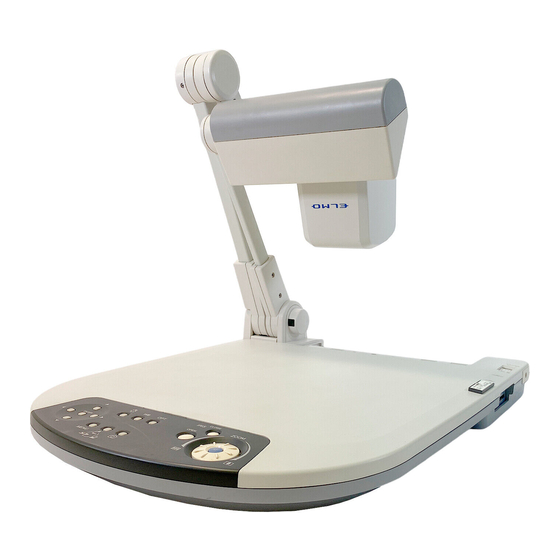
ENGLISH PART NAMES AND FUNCTIONS Name of Each Part I Appearance Front e e e r r r t t t Front Name Camera head Lamp head Lamp column Camera column Infrared sensor Front operating panel Stage Wireless remote control u u u Side panel Rear panel... -
Page 11: Functions
Functions I Front Operating Panel * Hereinafter the menu items to be displayed/selected on the monitor or projection screen are referred to as "OSD (On-Screen Display)." Name q OSD ENTER (Fix) Opera- w tion (Direction) To select the OSD item, move the selection frame (cursor) (Menu Delete) (Lamp) (White Balance) -
Page 12: Rear Panel
ENGLISH I Rear Panel Name q DVI OUT To output digital video signal to the projector, the (DVI Output Terminal) PC monitor or other DVI input device w RGB OUT To output analog video signal to the projector, the (Analog RGB PC monitor or other RGB input device Output Terminal) e RGB IN... -
Page 13: Side Panel
I Side Panel Name q USB (Compliant with 2.0) (SD Card Slot) e Main Switch r LCD Monitor Mounting Seat ENGLISH Function To transfer the data recorded in an SD card to the connected PC, or to transfer image or control the main unit by using the software contained in the Utility Software CD-ROM To insert an SD card... -
Page 14: Osd (On-Screen Display)
ENGLISH OSD (On-Screen Display) The menu items displayed/selected on the monitor or the projection screen are referred to as "OSD (On-Screen Display)." When the [MENU] button on the front operating panel or on the wireless remote control is pressed, the OSD menu is displayed on the monitor screen. By pressing the [MENU] button again, the OSD menu disappears. - Page 15 Name Top hierarchy 2nd hierarchy Posi/Nega Posi (Posi) (Posi/Nega) Nega (Nega) Color/B&W Color (Color) (Color/Black and B&W (Black and White) White) Text (Text) Image Rotation ON (180° rotate) (Image Rotate) OFF (0°) Preset 1 (Memory No.1) (Position Save) 2 (Memory No.2) 3 (Memory No.3) 4 (Memory No.4) 5 (Memory No.5)
-
Page 16: (Menu When Image Stored In An Sd Card Is In Display)
ENGLISH OSD (On-Screen Display) Display example of the top and 2nd hierarchies White Balance Auto/One-Push R-Gain Manual B-Gain 2nd hierarchy Iris Edge Effect Gamma Top hierarchy I SD Mode (Menu when image stored in an SD card is in display) Name Top hierarchy 2nd hierarchy 3rd hierarchy Delete... - Page 17 Name Top hierarchy 2nd hierarchy 3rd hierarchy Slide Effect Show (Effect of Image Random Settings Feed) Top down (Slide Show Left to right Set) Bottom up Right to left P.82 LT to RB RT to LB RB to LT LB to RT Random block Fade in/out Overlap...
-
Page 18: Wireless Remote Control
ENGLISH Wireless Remote Control Name q PRESET (State Save) w CALL (State Call) e (Memory No.) Function To save the current setting state of the unit Use this function together with the memory No. To call the setting state Use this function together with the memory No. To indicate the memory No. - Page 19 Name r (OSD MENU (Menu) Operation) ENTER (Input) (Direction) (Menu Cancel) To cancel the OSD from the screen when the top OSD item i POSI/NEGA (Posi/Nega) o COLOR/B&W (Color/Black and White) !0 IRIS (Iris) NORMAL (Normal) To return the Auto Iris to the factory default setting OPEN (Open) CLOSE (Close) !3 ZOOM...
-
Page 20: Receivable Range
ENGLISH I Receivable Range Point the infrared emitting part of the wireless remote control at the infrared sensor of the main unit, and press the button for desired function. The receiving range may be reduced when the main unit is placed in direct sunlight, near an inverter fluorescent lamp or in any other unfavorable surrounding. -
Page 21: Setting Up Setting Up
SETTING UP Setting Up Lift the camera column. Simultaneously, the lamp column is also lifted. Turn the camera head. Move the lamp column and the lamp head to an appropriate position as shown in the right figure. ENGLISH... -
Page 22: Connecting Of Video Cables
ENGLISH Connecting of Video Cables USB terminal •To PC SD card To protect this product and the peripheral units to be connected to this product, be sure to turn OFF the power supply to all units beforehand. When plugging in/out the connection cable, hold the plug part of the cable. q Connecting to the PC with a USB cable Connect a USB cable to the [USB] terminal on the side panel. - Page 23 r Connecting to the unit having the analog RGB output terminal Connect the analog RGB cable to the [RGB IN] terminal on the rear panel. When a laptop having an external output mode switching function is used, switch the video output of the Camera to [RGB IN] and then set the laptop to the external output mode •...
-
Page 24: Storing
ENGLISH STORING Storing As shown in the right figure, turn the lamp head and the lamp column and fold them down on the stage. Turn the camera head and the camera column and fold them down on the stage. - Page 25 ENGLISH...
-
Page 26: Operation Procedure
ENGLISH OPERATION PROCEDURE When connecting this product and the peripheral units, be sure to turn OFF the power supply to all units beforehand. Presentation using printed materials q Setting the main unit Set the main unit as show in the above figure, connect the main unit to the projector or the PC monitor, and then turn ON the power supply. -
Page 27: Presentation Using Sd Card (Option)
This product can store images up to 2048 pcs. This product is not compatible with SDHC cards. Use a card recommended for this product. ELMO is not liable for any damage caused by the loss of the data in the SD card or passive damage. -
Page 28: Saving The Image
Be sure to try out shooting and saving beforehand to confirm the normal saving of the image. If the image fails to be saved due to some problems in the camera or SD card, ELMO is not liable for any compensation for the recorded contents. -
Page 29: Deleting The Image
I Deleting the Image (1) Press the [ ] button on the front operating panel or wireless remote control or press the [ ] button on the wireless remote control to have the images in the SD card displayed on the full-screen or split screen. (2) Select the image to be deleted with the direction buttons [ operating panel or wireless remote control. -
Page 30: Presentation Using The Attached Software
USB-connected PC Set [USB Mode] to [Application] on the OSD. "Utility Software" is downloadable from the homepage of ELMO or in the CD-ROM supplied from ELMO. "Utility Software" contains the PC link software "Image Mate for Presentation", "Image Mate for Movie Creation"... -
Page 31: Transferring The Images From The Sd Card Into The Usb-Connected Pc
Transferring the images from the SD card into the USB-connected PC Set [USB Mode] to [Mass Storage] on the OSD. Insert the SD card with the labeled side up. Forcing it in the wrong way may cause a malfunction. When this product is USB-connected to the PC, image data in the SD card can be transferred into the PC. -
Page 32: Shooting Off The Stage
ENGLISH Shooting off the stage <Forward shooting> When the camera head is set horizontally, wall, distant view, etc. can be shot. When the object is in the distant view, open the close-up lens holder forward. To shoot horizontally, turn the image by 180° by pressing the [IMAGE ROTATION] button or setting the OSD accordingly. -
Page 33: Various Functions And Operations
VARIOUS FUNCTIONS AND OPERATIONS Lighting Front operating panel When the [ ] button on the front operating panel or wireless remote control is pressed, the fluorescent lamp lights up in 1 – 3 seconds. Each time the [ button is pressed, the fluorescent lamp turns ON/OFF alternately. -
Page 34: Zoom
ENGLISH Zoom Front operating panel When the zoom dial [ operating panel is turned or the zoom button [ ] on the wireless remote control is pressed, the document display range can be adjusted. According to the zoom dial turning angle, the zooming speed varies in 3 steps (3-step speed change). -
Page 35: White Balance
White Balance Front operating panel I [Auto/One-Push] (Auto Track/Auto Adjust and Fix) The Auto (auto track) mode for adjusting the white coloring automatically according to the document or lighting condition and the One-Push (auto adjust and fix) mode for maintaining the automatically adjusted state can be switched alternately. -
Page 36: Image Selection
ENGLISH Image Selection Front operating panel Each time the [ operating panel or wireless remote control is pressed, the image is switched in order of the camera image to the image inputted in the analog RGB input terminal [RGB IN], then to the image in the SD card, and then to the camera image again. -
Page 37: Input Image Signals To Analog Rgb Input Terminal [Rgb In] That Enables Output From Video Output Terminal [Video Out] Or [S-Video Out]
I Input Image Signals to Analog RGB Input Terminal [RGB IN] That Enables Output from Video Output Terminal [VIDEO OUT] or [S-VIDEO OUT] Signal Frequency Horizontal Vertical Mode name VGA1 37.861 84.889 VGA2 37.861 85.080 VGA3 37.927 85.039 VGA@60Hz 31.469 59.941 VGA@72Hz 37.861... -
Page 38: Focus
ENGLISH Focus Front operating panel The focus on the object is adjusted. I Auto Focus When the [AF] button on the front operating panel or wireless remote control is pressed, the camera is focused automatically. This product is of one-shot auto focus type. -
Page 39: Manual Focus
I Manual Focus When the focus button [FOCUS · NEAR] or [FOCUS · FAR] on the wireless remote control is pressed, the height on which the camera is focused changes. This function is used for focusing the camera on any portion of a 3D object or the like. Limit of focus adjustment: •... -
Page 40: Iris
ENGLISH Iris Front operating panel When the [IRIS · OPEN] button or [IRIS · CLOSE] button on the front operating panel or wireless remote control is pressed, the lens iris is adjusted for image brightness. This adjustment can be made in either of the following 2 modes, which are set in [Iris] on the OSD: I Auto Brightness Adjustment... -
Page 41: State Presetting
State Presetting The setting position of this product can be saved/called. Up to 6 positions can be saved. The presets that can be saved are as follows: • Current zoom field angle • Iris state • White Balance state • Edge Effect settings •... -
Page 42: Mounting The Lcd Optional Monitor
ENGLISH Mounting the LCD Optional Monitor To mount the LCD monitor (LM-5611A) on option, the LCD monitor bracket (MS-30) is required. As show in the right figure, connect the composite video output terminal [VIDEO OUT] of this product to the LCD monitor (LM-5611A) with the video cable with RCA pin plug (supplied as an accessory on standard or available in the market). -
Page 43: Rs-232C Specifications
RS-232C SPECIFICATIONS This product can be controlled from a PC connected to this product through the RS-232C terminal [RS-232C]. Setting Up q Connect this product to a PC with an RS-232C cable. When using an RS-232C cable available on the market, make sure that pin connections are the same as below. -
Page 44: Data Format Specification
ENGLISH Data Format Specification This command is executed in the form of 1-command/1-packet. The next command is not accepted until the previous processing is completed. • The communication command always starts with STX (Start of Text), and ends with ETX (End of Text). -
Page 45: Transmission Specifications
Transmission Specifications • Full duplex start-stop sync. mode • Start bit • Data bit • Stop bit • Parity bit • X parameter • Baud rate (Communication speed) : 9600bps UART Communication Format Commands, parameters and data are all transmitted in ASCII code. Function Command Parameter... - Page 46 ENGLISH Function Command Slide-show image 0 (All) feed effect 1 (Random) 2 (Top down) 3 (Left to right) 4 (Bottom up) 5 (Right to left) 6 (LT to RB) 7 (RT to LB) 8 (RB to LT) 9 (LB to RT) A (Random block) B (Fade in/out) C (Overlap)
-
Page 47: About Connection
Function Command Parameter Image rotation 0 (0°) 1 (180°) Edge effect 0 (OFF) 1 (Low) 2 (Mid) 3 (High) White balance AW 0 (Manual) 1 (Auto) 2 (One Push) 3 (R_Up) 4 (R_Down) 5 (B_Up) 6 (B_Down) Text 0 (OFF) 1 (ON) Posi/Nega 0 (Posi) -
Page 48: Troubleshooting
ENGLISH TROUBLESHOOTING Symptoms and Confirmation Check the following items. If any abnormality is found, consult the seller from whom you have purchased this product or our branch/office near your location. Symptom No image is displayed • The cable is not connected correctly to the video-in terminal of the on the TV monitor. -
Page 49: General
SPECIFICATIONS I General Item Power source 12VDC (AC adapter: 100 ~ 240VAC) Power consumption 30W (AC adapter included) Outside dimensions 377×482×180mm (14.8×19.0×7.1 in) (When folded) 377×482×582mm (14.8×19.0×22.9in) (When set up) Weight Approx. 4.7kg (10.4 lbs) (Main body only) Input selection Main body/External one system Output terminal DVI output... -
Page 50: Main Camera
ENGLISH I Main Camera Item Lens Shooting speed Shooting area Limit of focus adjustment Optical zoom Digital zoom Focus Iris Image pick-up element Total picture elements Effective picture elements Synchronized signal Resolution DVI output Analog RGB output Composite video output S-video output White balance Video output selection... -
Page 51: Supplied Accessories
S-video cable (Mini DIN 4P connector) (2m) Analog RGB cable (DSUB 15P connector) (2m) Infrared wireless remote control Batteries (Type R03, AAA) Instruction Manual for P10S Warranty Card for P10S USB cable (1.8m) Utility Software Installation Manual Utility Software CD-ROM I Options •... - Page 52 ENGLISH...
Need help?
Do you have a question about the P10S and is the answer not in the manual?
Questions and answers