Table of Contents

Related Manuals for Elmo P100


Summary of Contents for Elmo P100
-
Page 1: Instruction Manual
Français P000~P000 Deutch P000~P000 English P50~P97 P00~P00 Français P000~P000 Deutch P000~P000 DOCUMENT CAMERA P100 INSTRUCTION MANUAL Please read this instruction manual carefully before using this product and keep it for future reference. -
Page 2: Important Safeguards
ENGLISH IMPORTANT SAFEGUARDS I Read Instructions – All the safety and operating instructions should be read before the appliance is operated. I Retain Instructions – The safety and operating instructions should be retained for future reference. I Heed Warnings – All warnings on the product and in the operating instructions should be adhered to. - Page 3 I Grounding or Polarization – This product may be equipped with either a polarized 2-wire AC line plug (a plug having one blade wider than the other) or a 3-wire grounding type plug, a plug having a third (grounding) pin. The 2-wire polarized plug will fit into the power outlet only one way.
- Page 4 ENGLISH I Damage Requiring Service – Unplug this product from the wall outlet and refer servicing to qualified service personnel under the following conditions: G When the power-supply cord or plug is damaged. G If liquid has been spilled, or objects have fallen into the product.
- Page 5 WARNING: TO REDUCE THE RISK OF FIRE OR ELECTRIC SHOCK, DO NOT EXPOSE THIS PRODUCT TO RAIN OR MOISTURE. THIS IS A CLASS A PRODUCT. IN A DOMESTIC ENVIRONMENT THIS PRODUCT MAY CAUSE RADIO INTERFERENCE IN WHICH CASE THE USER MAY BE REQUIRED TO TAKE ADEQUATE MEASURES.
-
Page 6: Before You Use
ENGLISH BEFORE YOU USE I The power cord applicable to the local power specifications is attached. Be sure to use the power cord applicable to your local power specification. I Do not leave this product under direct sunlight or by heaters, or this product may be discolored, deformed, or damaged. - Page 7 ENGLISH...
-
Page 8: Table Of Contents
ENGLISH CONTENTS 1. PART NAMES AND FUNCTIONS Name of Each Part...59 Appearance...59 Functions ...60 Front Operating Panel ...60 Rear Panel ...61 Side Panel ...62 OSD (On-Screen Display) ...63 Camera Mode (Menu when camera image is in display)...63 Wireless Remote Control ...66 Receivable Range ...68 Battery Change ...68 2. - Page 9 CONTENTS 6. RS-232C SPECIFICATIONS Setting Up ...89 Cable Connection...89 Data Format Specification...90 Operation Command (PC → This product) ...90 Response Data Format (This product → PC) ...90 Transmission Specifications ...91 UART Communication Format ...91 Connection ...93 7. TROUBLESHOOTING Symptoms and Confirmation...94 Replacement of Lighting Lamp (Fluorescent Lamp)...94 8.
-
Page 10: Part Names And Functions
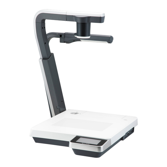
ENGLISH PART NAMES AND FUNCTIONS Name of Each Part I Appearance Front r r r e e e t t t w w w o o o Rear/Side q q q u u u y y y Front Name Camera head Lamp head Setup grip Camera column... -
Page 11: Functions
Functions I Front Operating Panel * Hereinafter the menu items to be displayed/selected on the monitor or projection screen are referred to as "OSD (On-Screen Display)". Name q LCD panel LAMP (Lamp) e TEXT (Text mode) r GRAPHICS (Color document) t BRIGHTNESS (Light) (Brightness) -
Page 12: Rear Panel
ENGLISH I Rear Panel Name q DVI OUT To output digital video signal to the projector, the (DVI Output Terminal) PC monitor or other DVI input device w RGB OUT To output analog video signal to the projector, the (Analog RGB PC monitor or other RGB input device Output Terminal) e RGB IN... -
Page 13: Side Panel
I Side Panel w w w q q q Name q USB (Compliant with 2.0) (SD Card Slot) e Main Switch ENGLISH e e e Function To enable the image transfer or the main unit control by using the utility software on the supplied CD-ROM when the camera is connected to the PC To insert an SD card To remove the SD card, push it in once... -
Page 14: Osd (On-Screen Display)
ENGLISH OSD (On-Screen Display) The menu items displayed/selected on the monitor or the projection screen are referred to as "OSD (On-Screen Display)". When the [MENU] button on the wireless remote control is pressed, the OSD menu appears on the monitor screen. (When this [MENU] button is pressed again, the OSD menu disappears.) Move to the item to be set by pressing the [ control, and press the [ENTER] button to fix the setting. - Page 15 Name Top hierarchy 2nd hierarchy Flickerless 60Hz (Flicker compensation) 50Hz ] indicates the factory default settings. The factory default settings of Flickerless vary according to the destination. The settings of USB Mode and Flickerless retain the last set state. OSD (On-Screen Display) I SD Mode (Menu when image stored in an SD card is in display) Name Top hierarchy 2nd hierarchy 3rd hierarchy...
- Page 16 ENGLISH Name Top hierarchy 2nd hierarchy 3rd hierarchy Slide Interval Show (Interval of Image 5 Sec Settings Feed) (Slide Show Set) Effect P.77 (Effect of Image Feed) Select (Object File) Order (Order of Image Feed) Repeat (Repeat) Start Slide Show (Slide Show Start) Display...
-
Page 17: Wireless Remote Control
Wireless Remote Control Name q PRESET (State Save) w CALL (State Call) e (Memory No.) ENGLISH Function To save the current setting state of the unit Use this function together with the memory No. To call the setting state Use this function together with the memory No. To indicate the memory No. - Page 18 ENGLISH Name r (OSD MENU (Menu) t Operation) ENTER (Input) (Directions) (Menu Cancel) i POSI/NEGA (Posi/Nega) o COLOR/B&W (Color/Black and White) !0 BRIGHT NORMAL (Normal) To return the automatic brightness adjustment level to the standard level NESS (Bright) (Brightness adjustment) (Dark) !3 ZOOM (Telescopic)
-
Page 19: Receivable Range
I Receivable Range Point the infrared emitting part of the wireless remote control at the infrared sensor of the main unit, and press the button for desired function. The receiving range may be reduced when the main unit is placed in direct sunlight, near an inverter fluorescent lamp or in any other unfavorable surroundings. -
Page 20: Setting Up Setting Up
ENGLISH SETTING UP Setting Up Release the lock by turning the security lock. As shown in the right figure, hold the setup grip and raise the camera column. At this time, the camera head slides up in conjunction with the rise of the camera column. - Page 21 If the camera column is pulled or pushed forcedly, the camera might be pushed out of position by a function not to break mechanical parts, and the camera image might be displaced from the display center. In this case, initialize the camera position as follows: Fold the camera column on the stage.
-
Page 22: Connecting Of Video Cables
ENGLISH Connecting of Video Cables SD card USB terminal •To PC To protect this product and the peripheral units to be connected to this product, be sure to turn OFF the power supply to all units beforehand. When plugging in/out the connection cable, hold the plug part of the cable. q Connecting to the PC with a USB cable Connect a USB cable to the [USB] terminal on the side panel. - Page 23 r Connecting to the unit having the analog RGB output terminal Connect the analog RGB cable to the [RGB IN] terminal on the rear panel. • Specifications of the analog RGB input terminal of this product Signal allocation 15 14 13 12 11 DSUB 15P shrink terminal (Female) Pin assignment...
-
Page 24: Storing
ENGLISH STORING Storing Return the lamp to the original position. Then, hold the setup grip of the camera column and fold the camera column. At this time, the camera head slides down and the lamp column also folds. Lock the camera column and the lamp column by turning the security lock. -
Page 25: Operation Procedure
OPERATION PROCEDURE When connecting this product and the peripheral units, be sure to turn OFF the power supply to all units beforehand. Presentation by Using Documents, Films, etc. q Setting the main unit Set the main unit as show in the above figure, connect the main unit to the projector or the PC monitor, and then turn ON the power supply. -
Page 26: Presentation Using Optional Sd Card (Option)
The resolutions of the image to be stored are 1280 × 1024 (SXGA output), 1280 × 720 (HDTV output) and 1280 × 960 (XGA output). This product can store images up to 2048 pcs. ELMO is not liable for any damage caused by the loss of the data in the SD card or passive damage. -
Page 27: Saving The Image
Presentation using optional SD card (Option) I Saving the Image (1) Press the [ ] button on the front operating panel or wireless remote control to switch the image mode to the Camera mode. (2) Press the [ ] button on the wireless remote control. (3) When the [ ] mark lights up on the screen, the image saving starts. -
Page 28: Formatting The Sd Card
ENGLISH I Deleting the Image (1) Press the [ ] button on the front operating panel or wireless remote control to display the images stored in the SD card in the full screen display mode or the divided screen display mode. (2) Select the image to be deleted by using the direction buttons [ remote control. -
Page 29: Presentation Using The Supplied Software With The Usb-Connected Pc
"Utility Software" is available from the supplied CD-ROM supplied from us. "Utility Software" contains PC link software "Image Mate for Presentation" and TWAIN driver "ELMO TWAIN DS" (VHN) to allow the following operation: • Transfer of moving/still images to the PC •... -
Page 30: Transferring The Images From The Sd Card Into The Usb-Connected Pc
ENGLISH Transferring the images from the SD card into the USB-connected PC Set [USB Mode] to [Mass Storage] on the OSD. When this product is USB-connected to the PC, image data in the SD card can be transferred into the PC. The Operating System (OS) of the connected PC should be Microsoft Windows 2000(SP4 or newer)/XP(SP2 or newer). -
Page 31: Shooting Off The Stage
Shooting off the stage <Forward shooting> When the camera head is set in the horizontal direction, walls, distant views, etc. can be shot. When the object is distant, open the close-up lens holder. Do not fold the camera column when the close-up lens holder remains open, or the close-up lens could be damaged. -
Page 32: Various Functions And Operations
ENGLISH VARIOUS FUNCTIONS AND OPERATIONS Lighting Front operating panel This camera is equipped with material illumination for presenting materials, such as printed matter, and base illumination for transparent materials, such as slide films and negative films. When the [ LAMP] button on the front operating panel or wireless remote control is pressed, the fluorescent lamp lights up in 1 –... -
Page 33: Zoom
Zoom Front operating panel When the zoom dial [ operating panel is turned or the zoom button [ ] on the wireless remote control is pressed, the document display range can be adjusted. According to the zoom dial turning angle, the zooming speed varies in 3 steps (3-step speed change). -
Page 34: Image Selection
ENGLISH Image Selection Front operating panel Each time the [ ], [ ] button and [ on the front operating panel or wireless remote control are pressed, the image is switched among the camera image, the image inputted in the analog RGB input terminal [RGB IN] and the image stored in the SD card. -
Page 35: Input Image Signal That Can Be Output From The Video Output Terminal [Video Out] Into The Analog Rgb Input Terminal [Rgb In]
I Input image signal that can be output from the video output terminal [VIDEO OUT] into the analog RGB input terminal [RGB IN] Signal Frequency Horizontal Vertical Mode name VGA1 37.861 84.889 VGA2 37.861 85.080 VGA3 37.927 85.039 VGA@60Hz 31.469 59.941 VGA@72Hz 37.861... -
Page 36: Focus
ENGLISH Focus Front operating panel The focus on the object is adjusted. I Auto Focus When the [AF] button on the front operating panel or wireless remote control is pressed, the camera is focused automatically. This product is of one-shot auto focus type. -
Page 37: Manual Focus
I Manual Focus When the focus button [FOCUS · NEAR] or [FOCUS · FAR] on the wireless remote control is pressed, the height on which the camera is focused changes. This function is used for focusing the camera on any portion of a 3D object or the like. Limit of focus adjustment: •... -
Page 38: Brightness Adjustment
ENGLISH Brightness Adjustment Front operating panel When the [BRIGHTNESS · front operating panel or wireless remote control is pressed, brightness of the image is adjusted through the adjustment of the lens iris. Two adjustment modes are available for this adjustment. Each mode is set by the [BRIGHTNESS] item of the OSD. -
Page 39: State Presetting
State Presetting The setting position of this product can be saved/called. Up to 8 positions can be saved. The presets that can be saved are as follows: • Current zoom field angle (Optical zoom range) • Brightness status • White Balance state •... -
Page 40: Rs-232C Specifications
ENGLISH RS-232C SPECIFICATIONS This product can be controlled from a PC connected to this product through the RS-232C terminal [RS-232C]. Setting Up q Connect this product to a PC with an RS-232C cable. When using an RS-232C cable available on the market, make sure that pin connections are the same as below. -
Page 41: Data Format Specification
Data Format Specification This command is executed in the form of 1-command/1-packet. The next command is not accepted until the previous processing is completed. • The communication command always starts with STX (Start of Text), and ends with ETX (End of Text). -
Page 42: Transmission Specifications
ENGLISH Transmission Specifications • Full duplex start-stop sync. mode • Start bit • Data bit • Stop bit • Parity bit • X parameter • Baud rate (Communication speed) : 9600bps UART Communication Format Commands, parameters and data are all transmitted in ASCII code. Function Command Auto Focus... - Page 43 Function Command Parameter Slide-show image 0 (Left to right) feed effect 1 (LT to RB) 2 (RT to LB) 3 (None) Slide-show object 0 (All) file 1 (Locked) Slide-show feed 0 (FWD) order 1 (BWD) Slide-show image 0 (3s) feed interval 1 (5s) 2 (10s) 3 (15s)
-
Page 44: Connection
ENGLISH Function Command Image rotation 0 (0°) 1 (180°) Edge effect 0 (OFF) 1 (Low) 2 (Mid) 3 (High) White balance AW 0 (Manual) 1 (Auto) 2 (One Push) 3 (R_Up) 4 (R_Down) 5 (B_Up) 6 (B_Down) Text 0 (GRAPHICS) 1 (TEXT1) 2 (TEXT2) 3 (TEXT3) -
Page 45: Troubleshooting
TROUBLESHOOTING Symptoms and Confirmation Check the following items. If any abnormality is found, consult the seller from whom you have purchased this product or our branch/office near your location. Symptom No image is displayed • The cable is not connected correctly to the video-in terminal of the on the TV monitor. -
Page 46: Specifications
ENGLISH SPECIFICATIONS I General Item Power source 12VDC (AC adapter: 100 ~ 240VAC) Power consumption 30W (AC adapter included) Outside dimensions 457×562×138mm (18.0×22.1×5.4 in) (When folded) 457×519×587mm (18.0×20.4×23.1 in) (When set up) Weight Approx. 8.5kg (18.7 lbs) (Main body only) Input selection Main body / External one system Output terminal... -
Page 47: Main Camera
I Main Camera Item Lens f = 4.9 ~ 78.4mm (16-time zoom), F = 2.7 Shooting speed 30 frames/sec Shooting area SXGA 405×324mm (15.9×12.8 in) max. 30×24mm (1.2×0.9 in) min. HDTV 405×224mm (15.9×8.8 in) max. 30×17mm (1.2×0.7 in) min. XGA 405×303mm (15.9×11.9 in) max. 30×23mm (1.2×0.9 in) min. Limit of focus With close-up lens: adjustment... -
Page 48: Lighting
The above specifications are subject to change without notice. Trademark Acknowledgements is a trademark of ELMO Co., Ltd. VESA and SVGA are registered trademarks of Video Electronics Standards Association. SXGA, VGA and XGA are trademarks or registered trademarks of International Business Machines Corporation.
Need help?
Do you have a question about the P100 and is the answer not in the manual?
Questions and answers