
Related Manuals for Kusam-meco KM 7016 IN


Summary of Contents for Kusam-meco KM 7016 IN
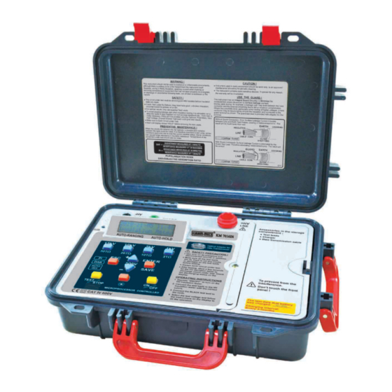
- Page 1 ® ® AN ISO 9001:2015 COMPANY Digital Variable High Voltage Insulation Tester KM 7016 IN INSTRUCTION MANUAL...
-
Page 2: Table Of Contents
Index Page 1. Safety Precautions..........2. Overview..............3. Features..............4. Specifications............5. Connections............6. Instrument layout............ 7. Measuring procedure..........7-15 8. Charge..............9. Maintenance & repair..........10. Interface connection and operation....... 18-29... -
Page 3: Safety Precautions
1. Safety Precautions Electricity can cause severe injuries even with low voltages or currents. Therefore it is extremely important that you read the following information before using your high voltage insulation tester. a. This Instrument must only be used and operated by a competent trained person and in strict accordance with the instructions. -
Page 4: Overview
g. Rated environmental conditions : (1) Indoor use. (2) Installation Category Ⅳ . (3) Pollution Degree 2. (4) Altitude up to 2000 meters. (5) Relative humidity 80% max. (6) Ambient temperature 0ºC~40ºC. h. Observe the international Electrical Symbols listed below : Meter is protected throughout by double insulation or reinforced insulation. -
Page 5: Features
3. Features ● Microprocessor controlled. ● 2 Lines x 16 characters, large intelligent LCD module. ● 30 insulation test voltages : 500V, 1kV, 1.5kV, 2kV, 2.5kV, 3kV, 3.5kV, 4kV, 4.5kV, 5kV, 5.5kV, 6kV, 6.5kV, 7kV, 7.5kV, 8kV, 8.5kV, 9kV, 9.5kV, 10kV, 10.5kV, 11kV, 11.5kV, 12kV,... -
Page 6: Specifications
4. Specifications From 500Vdc to 15kVdc Test Voltage Adjustable in 500V steps Preset buttons 1kV, 5kV, 10kV, 15kV 1TΩ / 0.5kV Measuring ranges 1TΩ at 0.5kV~30TΩ at 15kV 1kV : 0~200GΩ 5kV : 0~1TΩ ±(5%rdg+5dgt) 10kV : 0~2TΩ 15kV : 0~3TΩ Accuracy 1kV : 200GΩ~2TΩ... -
Page 7: Connections
5. Connections FIRST MEASUREMENT MEASURE WITHOUT THE GUARD TO TAKE EVERYTHING INTO ACCOUNT AND FIND OUT IF NEED CLEANING. DIRTY ELECTRICAL EQUIVALENT INSULATOR CIRCUIT DIRTY INSULATOR SECOND MEASUREMENT MEASURE WITH THE GUARD TO ENSURE INSULATOR IS CORRECT. TYPICAL TEST RESISTANCE DUE TO CONTAMINATION CAN BE VERY LOW AND LOWER THE TOTAL RESISTANCE. -
Page 8: Instrument Layout
6. Instrument layout -HV terminal GUARD terminal L.C.D. +HV terminal ⑭ 7016 IN ⑬ ⑫ ⑤ ② 30TΩ 20TΩ 10TΩ 2TΩ ③ ④ ⑥ ⑩ ⑧ ⑦ ⑪ ① ⑨ ① Power ON/OFF button ⑦ To subtract (-500V) button to ②... -
Page 9: Measuring Procedure
7. Measuring procedure This tester provide one main and five minor functions: Main Function: insulation resistance test. Minor functions: Function 1 ─ Voltage meter Function 2 ─ RTC Adjustment Function 3 ─ Test Timer Function 4 ─ LOG Display Function 5 ─ LOG Clear (A) Insulation resistance measurement test (main function) Note: 1. - Page 10 2. Press ① (ON/OFF) button. 2018 05 11 ‐ ‐ Insulation Meter (Main page) 3. Select test voltage: (1) Select one from 1kV, 5kV, 10kV or 15kV, press ( ② , ③ , ④ or ⑤ ) respectively. (2) To select voltage other than the four indicated, press anyone among ②...
- Page 11 6. Read the test value from LCD display. 200G 1100V I 2.5nA 7. Press ⑧ (TEST/ STOP); LCD shows the “discharging”. 200G Discharging 8. To store the data, press ⑨ (ENTER/SAVE); LCD displays the picture shown in below. 1.0KV 200G Note: When do the insulation test, always connect the test leads to the object we want to measure before pressing...
- Page 12 (B) Measure voltage (Voltage Meter) ─ Function 1 1. Press ① (ON/OFF) button. 2018 05 11 ‐ ‐ Insulation Meter (Main page) 2. Press ⑥ value-add “+” or ⑦ value-reduce “-”; LCD displays the picture shown in below: Function 1 Voltage Meter 3. Press ⑨ (ENTER/SAVE) to perform measurement; LCD displays the picture shown in below: Voltage Meter DC+ <...
- Page 13 (C) Date/time adjustment (RTC Adjustment) ─ Function 2 1. Press ① (ON/OFF) button. 2018 05 11 ‐ ‐ Insulation Meter (Main page) 2. Press ⑥ (value-add) "+" for 2 times; LCD display the following pictures respectively: Function 2 RTC Adjustmeter 3. Press ⑨ (ENTER/SAVE) button. 4. Press ⑥ (value-add) "+" or ⑦ (value-reduce) "-" till the correct voltage is reached.
- Page 14 (D) Measurement time setting (Test Timer) ─ Function 3 1. Press ① (ON/OFF) button. 2018 05 11 ‐ ‐ Insulation Meter (Main page) 2. Press ⑥ (value-add) "+" for 3 times; LCD display the following pictures respectively: Function 3 Test Timer 3. Press ⑨ (ENTER/SAVE), LCD displays the picture shown in below: Test Timer 10 minutes...
- Page 15 3. Press ⑨ (ENTER/SAVE), LCD displays the picture shown in below: 1.0KV 200G 4. Press ⑨ (ENTER/SAVE), LCD displays the “DAR” and “PI” picture shown in below: 1.0KV DAR:2.00 PI:1.00 5. Press ⑨ (ENTER/SAVE), LCD displays the “Volt” picture shown in below: 1.0KV Vout:1100V 6.
- Page 16 (F) Clear/erase the display of data stored (LOG Clear) ─ Function 5 1. Press ① (ON/OFF) button. 2018 05 11 ‐ ‐ Insulation Meter (Main page) 2. Press ⑥ (value-add) "+" for 5 times; LCD display the following pictures respectively: Function 5 LOG Clear 3. Press ⑨ (ENTER/SAVE) to inquire whether to clear up the data or not;...
- Page 17 (G) Introduction of other functions 1. Dielectric absorption ratio (DAR): Ratio of insulation resistance between 1-min and 30-sec 1-min insulation resistance DAR : 30-sec insulation resistance 2. Polarization index (PI): Ratio of insulation resistance between 10-min and 1-min 10-min insulation resistance PI : 1-min insulation resistance Lower insulation resistance tested takes longer test...
-
Page 18: Charge
8. Charge (A) Timing: After "Low Battery" is displayed on LCD display, perform battery charge; LCD displays the picture shown in below: Batt. Low 11 Insulation Meter (B) Process: 1. Plug one end of charger into the battery plug-in socket (Fig ⑬... -
Page 19: Maintenance & Repair
9. Maintenance & repair (A) To avoid and electric-shock or device damage, do not wet inner part of the tester. (B) Avoid the tester from being dropped down that would damage or disconnect devices apart. (C) Wipe the tester surface with soft, dry cloth and mild detergent. Prohibit from using sand paper or solvent. -
Page 20: Interface Connection And Operation
10. Interface connection and operation (A) Insulation Tester Installation Steps: 1. This program will install Insulation Tester on your computer automatically. 2. Click the “Next” key to set. 3. If you want to install a different folder, click Browse, and select another folder. - Page 21 4. Click the “Next” key. 5. It will show the information of all files are Installing to your personal computer. -19-...
- Page 22 6. It will show the information of Insulation tester has been successfully installed and then click “Finish” key. (Note: If your personal computer system is Windows 7, it will indicate the driver automatically. It’s necessary to install the driver if your computer system is not windows 7, then the driver is in the compact disk (CD).
- Page 23 (B) Windows Comm Port setting: 1. Plug the data transmission cable into the personal computer USB port. 2. On the windows interface, ① open the start Menu. ① 3. ② Right-click on Computer, ③ Click on Properties in the sub-menu. ②...
- Page 24 4. The windows appears Control Panel Home, On the left hand side of the window ④ click on Device Manger. ④ 5. The windows appears Device Manager. (Alternatively, you can: open the Run command window (Start Menu → Run… or press + R) and type “devmgmt. msc”...
- Page 25 6. ⑥ right click on the correct COM port and click on Properties in the sub-menu that pops up. ⑥ 7. In the window that appears ⑦ click on the Port Settings tab at the top and the display will change. ⑧...
- Page 26 8. ⑨ Click on the COM Port number list to expand it and click on a COM port number within the range of COM1 to COM8 (preferably one not in use, avoid choosing COM1; if all are in use and there are no other peripherals connected to your PC, assign it no any port between 1 and 8;...
- Page 27 ⑩ -25-...
- Page 28 (C) Insulation Tester Software Comm Port setting: 1. Connect data transmission cable to the Insulation Tester. 2. Click the icon of the “15kV Insulation Tester” on the desktop of the personal computer. 3. On the 15kV Insulation Tester window, select the correct “Comm Port and click the RS232 connection button.
- Page 29 (D) Insulation Tester Interface: ① ③ ② ① RS 232 Connection. ② Main operation interface. ③ Memory saving and downloading interface. ④ ⑥ ⑤ ④ Click the "Download Log from Device" key to download the current data and statistics. -27-...
- Page 30 ⑤ Click the "Chart Display" key to see the chart, picture shown in below: Click Click -28-...
- Page 31 ⑥ Click the "Save Log" key to the file, picture shown in below: -29-...
Need help?
Do you have a question about the KM 7016 IN and is the answer not in the manual?
Questions and answers