Advertisement
Quick Links
An ISO 9001:2008 Company
GENERAL SPECIFICATIONS
í Basic Accuracy : ± 0.05%
í Display : 4 Digit LCD display.
í Max. Allowable Voltage : 30V..
í Operating Temperature Range : 0 ~ 50°C.
Humidity range : £ 80% RH
í Storage Temperature Range : £ -10°C ~ 50°C
Humidity range : £ 90% RH
SAFETY :
Complies with IEC1010 (safety standard issued
by International Electrician Committee)
ELECTRICAL SPECIFICATIONS - KM-CAL-805
OUTPUT FUNCTION
Output
Range
DC Current
20 mA
Simu-transmitter
(absorption
-20 mA
Current)
Loop Power
24 V
INPUT FUNCTION
Input
Range
Voltage
28 V
20 mA
Current
Loop Current
20 mA
®
An ISO 9001:2008 Company
Chhaya com/D/chhaya/my documents/chhaya/backup/catlog/New catlog/2015 new arrival catalogs/KM-CAL-805.cdr
í Temperature Coefficient : 0.1 x (designated Accuracy) % /
°C (5°C ~ 18°C, 28°C ~ 40°C)
í Power : 1.5V x 2 alkaline batteries.
í Power Consumption : about 400mA / 3V in condition of
10mA with
1kW load.
í Dimension : 180 (L) x 90 (W) x 47 (D) mm (with holster)
í Weight : About 500g
ACCESSORIES :
User Manual, Test lead CF-36, (Clips for probe),
Holster & Carrying case.
Output Range
Resolution
0.000 ~ 22.000mA
0.001mA
0.000 ~ -22.000mA
0.001mA
Output Range
Resolution
-0.200 ~ 28.000V
1mV
-1.000 ~ 22.000mA
0.001mA
0.000 ~ 22.000mA
0.001mA
G-17, Bharat Industrial Estate, T. J. Road, Sewree (W), Mumbai - 400 015. INDIA.
Sales Direct.: 022-24156638,
Email : kusam_meco@vsnl.net,
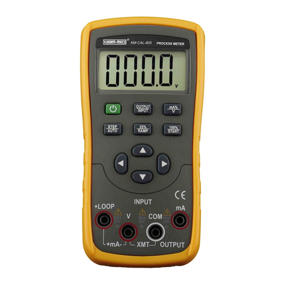
LOOP CALIBRATOR
Model KM-CAL-805
Accuracy
Remarks
± 0.05% set value + 4mA
Max. load 1KW at 20mA
Max. load 1KW at 20mA
Note:
± 0.05% set value + 4mA
power supply range :
5 ~ 25VDC
Max. Output current
± 10%
upto 25mA
Accuracy
Remarks
Input Resistance about
± 0.02% reading ± 2mV
1MW
± 0.02% reading ± 4mA
Resistance about 20W
Providing 24V
± 0.02% reading ± 4mA
Loop Power
Tel. : 022-24124540, 24181649,
Preliminary Data
All Specifications are subject to change without prior notice.
Fax : 022-24149659
Website : www.kusamelectrical.com
Advertisement

Subscribe to Our Youtube Channel
Related Manuals for Kusam-meco KM-CAL-805


Summary of Contents for Kusam-meco KM-CAL-805
- Page 1 G-17, Bharat Industrial Estate, T. J. Road, Sewree (W), Mumbai - 400 015. INDIA. Sales Direct.: 022-24156638, Tel. : 022-24124540, 24181649, Fax : 022-24149659 Email : kusam_meco@vsnl.net, Website : www.kusamelectrical.com An ISO 9001:2008 Company Chhaya com/D/chhaya/my documents/chhaya/backup/catlog/New catlog/2015 new arrival catalogs/KM-CAL-805.cdr...
- Page 2 Digital Hand Held Temperature Indicators ® G 17, Bharat Industrial Estate, T. J. Road, Sewree (W), Mumbai - 400 015. INDIA. Sales Direct : (022) 24156638 OPERATION MANUAL Tel. : (022) 24124540, 24181649. Fax : (022) 24149659 Email : kusam_meco@vsnl.net Website : www.kusamelectrical.com www.kusam-meco.co.in...
-
Page 3: Table Of Contents
® ® Section One Safety Information To ensure the safety operation, the following signs are used only TABLE OF CONTENTS as specified in this operation instruction: TITLE PAGE NO. Warning A warming shows that if the operation does not comply with the following correct instruction is possible to bring hazards to the user or cause Safaety Information .... -
Page 4: Instrument Panel Layout And Functions
® ® between any terminal and earth ground. Iustration of LCD Display Area Caution • No one is allowed to remove the spit case of the Instrument except professionals. • Periodically wipe the case with a damp cloth and detergent do not use any corrosive solvents. -
Page 5: Instrument Maintenance
® ® V. mA . % : These symbols denote the units of both present input Replacing the Batteries and output values. This Instrument is powered by two AA batteries (IECLR6) ON OFF : These symbols denote the turn- on or turn-off of any input / output signals. - Page 6 ® ® Figure 3-1 Replacing batteries Figure 3-2 Replacing fuse Section Four Power-on/off of Instrument power on/off Replacing Fuse Press the power key to turn on the power supply of the Instrument. Warning Then repress it to hold it in one second and the power will be off. When the power is turned on, the Instrument start to make self- To avoid personnel injury or damage to the meter, use only the dignosis internally and the full screen is in display.
-
Page 7: Output From Instrument
® ® Section Five Output from Instrument 2) Press the key (OUTPUT/IN) , and OUTPUT appears in the display. it denotes that the Instrument is in an output state; The Instrument produces the DC current from its appropriate 3) Press the key (mA%/V) ,to select the output to be set in ‘mA” output terminal (OUTPUT) set by the user or simulating a OR % and then the unit mA or mA% appears, in which 0% transmitter. - Page 8 ® ® Simulating Transmitter Output (XMT) 4) Press the key ( ) to be set to 100% and the current output will be 20mA Press the key ( ) to be set to 0% and the current 1) Insert one end of the test lead to the ‘XMT’ output jack of the output will be 4mA.
-
Page 9: Instrument Measurement
® ® Section Six Instrument Measurement Measuring DC Current 1) Insert one end of the test lead into the mA jack of the Warning Instrument (INPUT) terminal and connect the other end to the output of the user’s device as shown in Figure 5-3; During the operation, never apply more than 30V between any two terminals, or between any terminal and earth ground. - Page 10 ® ® Measuring DC Voltage Providing 24V Power Supply for Measuring Loop Current 1) Insert one end of the test lead into the V jack of the Instrument (INPUT) terminal and connect the other end to the output of the Insert the test lead into the +LOOP and mA input jacks of the user’s device as shown in Figure5-4;...
-
Page 11: Performance Index
® ® General Specification Press the key (100% / START) to store the selection; cut off the power again to exit from the maintenance function. Power Supply : 2 1.5V alkaline batteries (Lr6) Section Eight Performance Index Battery life : about 400mA/3V under the condition of 10mA with 1K load Output Output... - Page 12 ® ® Section Nine Calibration Ambient Condition for Calibration Note Ambient temperature : 23°C+1°C ; Relative humidity : 45 to 75% RH; Preheating : standard instrument should be preheated to • Calibration : In order to keep the designed accuracy of this specified time;...
- Page 13 ® ® Operating Input Calibration 2) Press the key (OUTPUT/ INPUT) to selest output function, and the LCD displays ‘ OUTPUT ’ ‘mA’ Operating calibrations in order of items and calibration points in Table 10-3; 3) Connect to the Instrument as shown in Figure 10-1; 4) Set the digital meter to an appropriate range;...
-
Page 14: Notice Of The Manual
® ® Figure 10-2 Figure 10-3 4) Set the Standard source to an appropriate range; 5) Press the key (STEP/AUTO) and the LCD displays ‘CAL FS’, and repeat the operation of steps 4. 5) Set the output of standard source as the value given in Table 10-3 and when the output stabilized, press the (100%/START) key and the LCD displays ‘SAVE’... -
Page 15: Test Certificate
® ® MUMBAI WARRANTY Each “KUSAM-MECO” product is warranted to be free from defects TEST CERTIFICATE in material and workmanship under normal use & service. The warranty period is one year (12 months) and begins from the date of despatch of goods. In case any defect occurs in functioning of the...
Need help?
Do you have a question about the KM-CAL-805 and is the answer not in the manual?
Questions and answers