Advertisement
100MSPS 2ch Digitizer Board for PCI
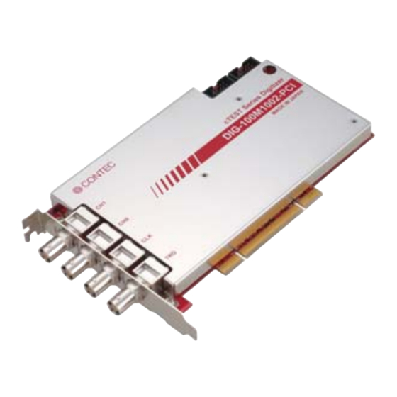
DIG-100M1002-PCI
* Specifications, color and design of the products are subject to
change without notice.
Features
Free yourself from visual inspection. The inspected input
signal can be automatically judged whether OK or NG.)
By comparing the sampled
signal waveform with the pass
range which is set beforehand, a
pass or fail judgment can be
done automatically with the
waveform level.
It is intended to not only save labor on present visual
examination greatly but also improve/uniform the quality.
Moreover, the "Mask Editor Software" is supplied as a tool to
create comparison waveform data and is Windows exclusive
use, by which the following operation can be done, drawing on
screen directly/drawing straight line/sine wave with mouse,
drawing constant voltage/ square wave/triangular
wave/step//ramp/sawtooth wave with mathematics functions.
"Front panel software" is supplied that can be used as the
oscilloscope or the waveform judgement instrument
easily.
The "Front Panel Software", an
application that makes an image
of oscilloscope or waveform
judgment instrument, is
supplied. You can use it easily
with no need of programming.
Moreover, you can use it to check the configured execution
environment, because it features the functionality of diagnosing
and reporting the status of the board and device driver.
Resolution 10bits, maximum conversion speed is 10MSPS
(100nsec), with simultaneous sampling of 2channels at a
time
A 10bits high-speed A/D covonverter is used, the measurement
at the highest conversion speed of 100MSPS(10nsec) is
possible. It is possible to sample 2 channels simultaneously.
Moreover, it is equipped with a mass on-board memory of 32M
data that archieves continuous sampling, regardless of the
processing performance of the PC. It is also equipped with
bus master transfer function by which the sampling data is
transferred to PC memory with high speed.
A variety of settings for signal input such as impedance,
range, filter and coupling can be performed.
DIG-100M1002-PCI
This product is a PCI-bus compliant digitizer board. It is
designed with the following features:
10-bit resolution, up to 100MSPS (10nsec) conversion speed,
sampling 2 channels simultaneously. In addition, it features
with the PASS/FAIL judgment functionality by comparing input
data with the set standard data (mask data) one by one.
The large (32M data) on-board memory and bus master
transfer function allow continuous data acquisition to be
performed at high speed for a long period.
The automation of the measurement is facilitated by factors
such as various sampling control and waveform judgment
function based on mask data.
The mask editor software is attached as a tool to generate
comparison waveform data. You can create the waveform data
by drawing on screen directly with mouse or drawing with
mathematics functions (input numerical values). Moreover, you
can make use of the supplied front panel soft as an
oscilloscope or a waveform judgment instrument. In addition,
Windows API is also supplied, so that you can also program in
Visual Baisc or Visual C++.
Analog input channel's input impedance can be selected
between 50Ω and 1MΩ. The measurement using a
general-purpose passive probe is also possible by 1MΩ.
According to the voltage level of signal source connected, a
number of ranges can be switched (When 1MΩ is set, there are
10 ranges between 40mVpk[±20mV] and 40Vpk[±20V]. When
50Ω is set, there are 8 ranges between 40mVpk[±20mV] and
10Vpk[±5V]) , so that you can make good use of the 10bit
resolution. By enabling the noise filter (low pass filter:
20MHZ ), it is possible to perform the measurement with
reducing the influence of mixed high frequency noise from
signal source and ambient environment.
The input coupling can be selected from AC/DC/GND.
(AC is only available when 1MΩ is set.)
The synchronization between external instrument and the
board is possible with the reference clock I/O.
The synchronization between other measuring instrument or
another board with the same type becomes easily for that the
reference clock (10MHz) can be input/output.
It is possible to expand the number of channels by the
synchronization between another board with the same type,
and measure the mixed signal by the synchronization between
other measuring instrument..
Sampling can be controlled by software, conversion data
comparison, external trigger, event controller output, and
similar start and stop conditions
Sampling can be setup to be started and stopped by software,
conversion data comparison, external trigger, or event
controller output. Control of sampling start and stop is
completely independent and a separate setting is provided for
each. It is also possible to specify that sampling stop after a
specified number of samples. There are two kinds of
comparison for conversion data. The one is implemented by
comparing the conversion data edge (rising edge, falling edge
or both edges), the other one is implemented by window trigger
that is satisfied when conversion data go inside/outside a
certain boundary.
BNC connector used for analog input, trigger and
reference clock
The BNC connector used for the connector has a characteristic
impedance of 50Ω and is of a type commonly used for high
speed analog signal.
Ver.1.03
1
Advertisement
Table of Contents

Related Manuals for Contec DIG-100M1002-PCI


Summary of Contents for Contec DIG-100M1002-PCI
- Page 1 Ver.1.03 100MSPS 2ch Digitizer Board for PCI DIG-100M1002-PCI This product is a PCI-bus compliant digitizer board. It is designed with the following features: 10-bit resolution, up to 100MSPS (10nsec) conversion speed, sampling 2 channels simultaneously. In addition, it features with the PASS/FAIL judgment functionality by comparing input data with the set standard data (mask data) one by one.
-
Page 2: Specification
*2 : Do not input a voltage over the Max. input voltage. It may cause failure. *3 : When 2ch are used, the Max. conversion speed is 50MHz (when data logger mode is used.). -100 0.05 0.15 0.25 0.35 0.45 Frequency(100MHz) DIG-100M1002-PCI... - Page 3 *9 : This product requires +5V and +3.3V power supply from expansion slots. : BNC-B100 (1m), BNC-B200 (2m), BNC-B300 (3m) Check the CONTEC’s Web site for more information on these options. Board Dimensions 176.41(L) Packing List Board [DIG-100M1002-PCI] …1...
-
Page 4: Block Diagram
- BNC connector [plug type] Analog Ground B6252HB-NPP3G-50 cTEST Series Digitizer [mfd. by AMPHENOL TAIWAN] DIG-100M1002-PCI or equivalence to it MADE IN JAPAN CAUTION Do not touch the external connector (BNC connector) when the power is on. Otherwise this may malfunction, cause a failure due to static electricity. -
Page 5: Synchronization Control Connectors
CLK (IN) among boards even when channels are expanded. When board models are different, data still remains compatible since Digital Ground sampling clock start and stop are dependent on the master. Connect the SC cable. Designate master/slave with the software. DIG-100M1002-PCI... - Page 6 Connect CN6 with a smaller ID number to CN7 with a greater ID number with the cable. You should only use the cable that came with the board. ID = 0 ID = 1 ID = 2 DIG-100M1002-PCI...
Need help?
Do you have a question about the DIG-100M1002-PCI and is the answer not in the manual?
Questions and answers