Table of Contents
Advertisement
Quick Links
Model L5034 G4
Operator's/Parts Manual
UNIT SERIAL NUMBER ___________________________
MANUAL NUMBER: 305438-I
EFFECTIVE 06/2020
1330 76TH AVE SW
CEDAR RAPIDS, IA 52404-7052
PHONE (800) 363-1771 | FAX (319) 286-3350
www.newleader.com
Copyright 2019 Highway Equipment Company, Inc.
Now doing business as New Leader Manufacturing
Advertisement
Table of Contents
Troubleshooting

Subscribe to Our Youtube Channel
Related Manuals for New Leader L5034 G4


Summary of Contents for New Leader L5034 G4
- Page 1 Operator’s/Parts Manual UNIT SERIAL NUMBER ___________________________ MANUAL NUMBER: 305438-I EFFECTIVE 06/2020 1330 76TH AVE SW CEDAR RAPIDS, IA 52404-7052 PHONE (800) 363-1771 | FAX (319) 286-3350 www.newleader.com Copyright 2019 Highway Equipment Company, Inc. Now doing business as New Leader Manufacturing...
-
Page 2: Table Of Contents
L5034G4 Header Table of Contents Interactive Features �����������������������������������������������������������������������������������������������������������������������������������5 Warranty �����������������������������������������������������������������������������������������������������������������������������������������������������6 Preface ��������������������������������������������������������������������������������������������������������������������������������������������������������7 Safety ����������������������������������������������������������������������������������������������������������������������������������������������������������8 Important Safety Information ����������������������������������������������������������������������������������������������������������8 Safety Alert Symbols ������������������������������������������������������������������������������������������������������������������������8 General Safety Rules ���������������������������������������������������������������������������������������������������������������������������������9 Safety Decals ��������������������������������������������������������������������������������������������������������������������������������������������19 Safety Decal Maintenance �������������������������������������������������������������������������������������������������������������19 Safety Decal Installation ����������������������������������������������������������������������������������������������������������������19 General Description ��������������������������������������������������������������������������������������������������������������������������������25 Dimensions &... - Page 3 L5034G4 Header Table of Contents Valve Calibration Adjustment ������������������������������������������������������������������������������������������������������� 51 Alarm Settings �������������������������������������������������������������������������������������������������������������������������������� 53 Reconfigure System ����������������������������������������������������������������������������������������������������������������������� 54 Switch Assignment ������������������������������������������������������������������������������������������������������������������������� 55 Component Calibration ����������������������������������������������������������������������������������������������������������������� 56 Spinner Disc Calibration ���������������������������������������������������������������������������������������������������������������� 56 Conveyor Calibration ��������������������������������������������������������������������������������������������������������������������� 57 Operations/Features ���������������������������������������������������������������������������������������������������������������������� 60 Hydraulics ���������������������������������������������������������������������������������������������������������������������������������������� 64 Bin Flush ������������������������������������������������������������������������������������������������������������������������������������������...
- Page 4 L5034G4 Header Instructions for Ordering parts ��������������������������������������������������������������������������������������������������������������� 87 Body ���������������������������������������������������������������������������������������������������������������������������������������������������������� 88 Mounting ����������������������������������������������������������������������������������������������������������������������������������������� 88 Sight Window ��������������������������������������������������������������������������������������������������������������������������������� 89 Feedgate ����������������������������������������������������������������������������������������������������������������������������������������� 90 Fenders ������������������������������������������������������������������������������������������������������������������������������������������� 92 Mud Flaps ��������������������������������������������������������������������������������������������������������������������������������������� 93 Pump Hydraulics ����������������������������������������������������������������������������������������������������������������������������� 94 Relief Valve Groups ������������������������������������������������������������������������������������������������������������������������ 96 Pressure Gauge Kit ������������������������������������������������������������������������������������������������������������������������� 97 Main Bin ������������������������������������������������������������������������������������������������������������������������������������������...
-
Page 5: Interactive Features
Electronic format viewers can Hyperlinks within the content are denoted by click these links for direct access to New Leader online features� Internet access is required� www.NewLeader.com 305438-I (800) 363-1771 - 5 -... -
Page 6: Warranty
Warranty Insert Current New Leader Warranty... -
Page 7: Preface
New Leader Manufacturing reserves the right to make alterations or modifications to this equipment at any time. The manufacturer shall not be obligated to make such changes to machines already in the field. -
Page 8: Safety
Important Safety Information Figure 1�1 - The need for safety cannot be stressed strongly enough in this manual� At New Leader Manufacturing, we urge you to make safety your top priority when operating any equipment. We firmly advise that anyone allowed to operate this machine carefully read, learn and understand all messages and information in this manual and on machine’s safety decals before operating machine, as well as... -
Page 9: General Safety Rules
L5034G4 General Safety Rules Operations PREPARE FOR EMERGENCIES Figure 1.2 - Be prepared if a fire starts. Keep a fully charged fire extinguisher and first aid kit in accessible place on the vehicle at all times� Fire extinguisher must be Type ABC or Type BC. Keep emergency numbers for doctors, ambulance service, hospital and fire department available at all times. - Page 10 L5034G4 General Safety Rules Operations HANDLE HAZARDOUS MATERIALS SAFELY Figure 1�5 - Materials to spread can be dangerous� Improper selection, application, use or handling may be a hazard to persons, animals, plants, crops or other property� A Safety Data Sheet (SDS) provides specific details on chemical products: physical and health hazards, safety procedures and emergency response techniques�...
- Page 11 L5034G4 General Safety Rules Operations AVOID MOVING PART HAZARDS Figure 1�8 - Entanglement in rotating drive lines or moving parts will cause serious injury or death� Stay clear of all moving parts, such as shafts, couplings and universal joints� Make sure all personnel are clear of machine before starting� Figure 1�8 Figure 1�9 - Do not operate machine without all guards and shields closed and secured�...
- Page 12 L5034G4 General Safety Rules Operations DO NOT CLIMB OR STAND ON MACHINE Figure 1�12 - Never allow any personnel to ride in or on the machine� Use only inspection ladder or portable ladder to view the unit� Use caution when getting on and off the ladder, especially in wet, icy, snowy or muddy conditions�...
- Page 13 L5034G4 General Safety Rules Transportation & Handling TRAVELING & TRANSPORTING ON PUBLIC ROADS Always walk around and visually inspect the machine before traveling on public roads� Check for damage and/or faulty components that can fail and create a hazard or unsafe condition. Make sure all machine systems operate properly, including but not limited to: headlights, tail and brake lights, hazard warning lights, turn indicators, parking brake, horn and rear view mirrors�...
- Page 14 Never modify any equipment or add attachments not approved by New Leader Manufacturing� Figure 3�1 DO NOT SERVICE OR ADJUST MACHINE WHILE IN MOTION Figure 3�2 - Never lubricate, service or adjust the machine or any of its components while they are moving�...
- Page 15 Use power tools only to loosen threaded parts and fasteners� Using power tools to tighten may cause over-tightening and component damage� Use only service parts meeting New Leader specifications. Figure 3�6 www.NewLeader.com 305438-I (800) 363-1771...
- Page 16 L5034G4 General Safety Rules Maintenance HIGH PRESSURE FLUID HAZARDS Figure 3.7 - Escaping fluid under pressure can penetrate the skin causing serious injury� Always stop machine, allow to cool and relieve pressure before servicing hydraulic system� Never open hydraulic lines under pressure� Make sure all connections are tight and all hoses are in good condition before pressurizing system�...
- Page 17 L5034G4 General Safety Rules Maintenance CLEAN MACHINE OF HAZARDOUS CHEMICALS During application of hazardous chemicals, residue can build up on the inside or outside of the vehicle� CAUTION Clean vehicle according to use instructions of hazardous chemical� Figure 3.10 - When exposed to hazardous chemicals, clean exterior and interior of vehicle daily to keep free of the accumulation of visible dirt and contamination�...
- Page 18 L5034G4 General Safety Rules Storage PARK VEHICLE SAFELY Figure 4�1 - When leaving the vehicle unattended for any reason, be sure to: • Shut down PTO� • Shut off vehicle’s engine, and unit’s engine if applicable� • Place vehicle transmission in “Neutral” or “Park”� •...
-
Page 19: Safety Decals
Replace safety decals and signs that are missing or have become illegible� Replaced parts that displayed a safety sign should also display the current sign� Safety decals or signs are available from your dealer’s Parts Department or from New Leader Manufacturing by calling (800) 363-1771�... - Page 20 L5034G4 Safety Decals Cancer and Reproductive Harm - www.P65Warning.ca.gov 315865-A 1. CAUTION: TO AVOID INJURY OR MACHINE DAMAGE: • Do not operate or work on this machine without reading and understanding the operator’s manual� • Keep hands, feet, hair and clothing away from moving parts� •...
- Page 21 L5034G4 Safety Decals 4. WARNING: HIGH-PRESSURE FLUID HAZARD To prevent death or serious injury: • Do not check leaks with hands while system is operating as high pressure oil leaks can be dangerous! • Relieve pressure before disconnecting hydraulic lines or working on system� •...
- Page 22 L5034G4 Safety Decals 7. DANGER: FLYING MATERIAL AND ROTATING SPINNER HAZARD To prevent death or serious injury: • Wear eye protection� • Stop machine before servicing or adjusting� • Keep bystanders at least 60 feet away� 8. WARNING: FALLING HAZARD To prevent death or serious injury: •...
- Page 23 Refer to the “How to Check your Spread Pattern” manual for adjustment instructions� A spread pattern test kit is available from your New Leader dealer� Wind, humidity, rain and other adverse weather conditions can affect spread pattern, resulting in uneven crop growth and loss of yields�...
- Page 24 L5034G4 Informational Decals 2. NOTICE: CONVEYOR CHAIN LUBRICATION To avoid machine damage and premature wear: • Conveyor chain life will be noticeably extended by periodic lubrication. • Use a 75% diesel fuel and 25% number 10 oil mixture on the links and rollers. •...
-
Page 25: General Description
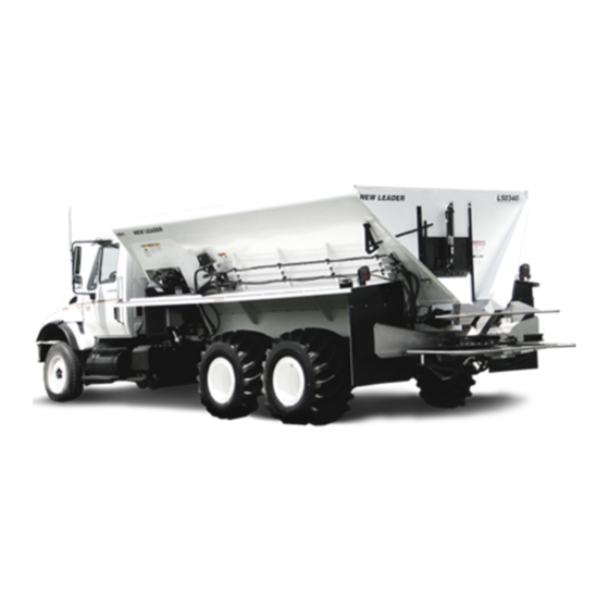
L5034G4 General Description Header The L5034G4 is a hopper type spreader intended for spreading feedlot manure, waste water sludge, industrial waste, paper mill waste, compost, marl, poultry litter and fly ash. It is intended for truck chassis or flotation vehicle mounting. The unit is hydraulically powered and provides independent variable speed control for the spinner and full automatic ground speed control for the conveyor�... -
Page 26: Dimensions & Capacities
L5034G4 Dimensions & Capacities Header (2997mm) (OUTSIDE) (1778mm) 128 (3251mm) (FENDER WIDTH) Cab to Axle or Cab to Unit Overall Lenth Body Length Frame Length Tandem Length CA/CT 13’ 196” (4978mm) 144” (3658mm) 147” (3734mm) 108” (2743mm) CA 14’ 208” (5283mm) 156”... -
Page 27: Initial Start
L5034G4 Initial Start-up Header WARNING Stand clear of moving machinery� NOTE: Do not load spreader with material� 1� Check entire unit to make sure all fasteners are in place and properly tightened per “Standard Torques” in this manual� 2� Make sure no other persons are in vicinity of spreader� 3�... -
Page 28: Field Testing
L5034G4 Field Testing Header The following procedure is a guide: NOTE: Do NOT fill speader with material 1� Field test over any suitable course which allows vehicle to be driven at speeds to be used while spreading� 2� Ensure unit has been properly serviced, that the hydraulic reservoir is full and gate valve under reservoir is fully open as applicable�... -
Page 29: General Operating Procedures
L5034G4 General Operating Procedures Header 1� Make sure unit has been properly serviced and is in good operating condition� It is highly recommended to run the spreader prior to loading material to ensure acceptable operation� 2� Program controller with correct data for material(s) and application� 3�... -
Page 30: Lubrication & Maintenance
L5034G4 Lubrication & Maintenance Header Preventative Maintenance Pays! The handling and spreading of commercial fertilizers is a most severe operation with respect to metal corrosion� Establish a frequent, periodic preventative maintenance program to prevent rapid deterioration to spreading equipment� Proper cleaning, lubrication and maintenance will yield longer life, more satisfactory service and more economical use of your equipment�... -
Page 31: Hydraulic Hose
L5034G4 Lubrication & Maintenance Header Hydraulic Hose Hose assemblies in operation should be inspected frequently for leakage, kinking, abrasion, corrosion or other signs of wear or damage� Worn or damaged hose assemblies should be replaced immediately� Testing should be conducted in approved test stands with adequate guards to protect the WARNING operator�... - Page 32 L5034G4 Lubrication & Maintenance Header Lubrication Make sure unit is clean and completely dry� Spray Nozzle Lubricate conveyor chain at the end of each day of usage using a mixture of 75% diesel fuel and 25% SAE 10 oil� Shut down spinner and run conveyor at 20 RPM for two full revolutions to lubricate chain�...
-
Page 33: Conveyor Gearcase
L5034G4 Lubrication & Maintenance Header Conveyor Gearcase Drain oil in a new unit after first two weeks (or not more than 100 hours) of operation, and flush gear case thoroughly with light oil. Refer to “Lubricant and Hydraulic Oil Specifications” section for proper grade oil and recommended amounts of lubricant�... -
Page 34: Lubricant & Oil Specifications
Extreme environments or dirty conditions may require the use of different oils� Consult your New Leader dealer or the Product Support Department at Highway Equipment Company for systems operating outside normal conditions�... -
Page 35: Lubrication Chart
L5034G4 Lubrication Chart Header Shut off all power and allow all moving parts to come to rest before performing any WARNING maintenance operation� The spreader should be regularly lubricated with the lubricants recommended in this manual in accordance with the following chart: Location Places Method... -
Page 36: Conveyor Selection
NR indicates the conveyor and/or spreader is not recommended for the specified application. The density provided was used to make the conveyor recommendation� If the density of the material to be spread is outside of those in the table, contact your New Leader dealer for the best conveyor for your application�... -
Page 37: Troubleshooting
L5034G4 Troubleshooting Header Hydraulic Schematic www.NewLeader.com 305438-I (800) 363-1771 - 37 -... - Page 38 L5034G4 Troubleshooting Header Spinner motors do not turn when spinner control valve is in running position or conveyor does not run when placed in “On” position� See reasons 1, 2, 3, 4, 6, 7, 8 & 9� Spinners turn but conveyor does not run in manual mode� See reasons 5, 7, 9 & 10� Console in operation mode, but the conveyor does not move when the machine moves�...
- Page 39 L5034G4 Troubleshooting Header Reason: Correction: 10� In line relief valve set too low� In line relief valve pressure should be 3100 PSI (214 bar)� Set spinner control valve to “0”� Disconnect pressure line, coming from rear port on spinner control valve, at control� Reconnect this line to flow meter inlet port.
-
Page 40: Standard Torques
Standard Torques L5034G4 Header CAP SCREW GRADE IDENTIFICATION - MARKINGS ON HEAD NO MARKINGS GRADE 2 THREE MARKS - 120 DEGREES APART GRADE 5 SIX MARKS - 60 DEGREES APART GRADE 8 USE GRADE 2 TORQUES FOR STAINLESS STEEL FASTENERS AND CARRIAGE BOLTS� TORQUE - FOOT-POUNDS CAP SCREW GRADE 2... -
Page 41: Controller Operations
UI (User Interface) - The displayed information and controls the user interacts with on the Display Monitor to make any necessary changes to implement performance� • ECU (Electronic Control Unit) - New Leader module that controls specific functions of the implement and is attached to the BUS� •... -
Page 42: Cab To Enclosure Diagram
L5034G4 Controller Operations Cab to Enclosure Diagram Battery www.NewLeader.com 305438-I - 42 - (800) 363-1771... -
Page 43: Modules To Function Diagram
L5034G4 Controller Operations Modules to Function Diagram Conveyor Conveyor Pressure Speed Conveyor Control Sensor Conveyor Pressure Conveyor Speed Conveyor Control Sensor Main Hydraulic Conveyor Spinner 1 Spinner 1 Hydraulic Speed Control Level Filter Speed Pressure Hydraulic Conveyor Conveyor Spinner 2 Chain Spinner 2 Restriction... -
Page 44: Requirements
L5034G4 Controller Operations Requirements System Requirements: Function: • Virtual Terminal version 3 that supports • VT will load New Leader UI and assign AUX-N functionality functions to in-cab switches� • Task Control (Multi-product up to 4 bins) • TC-BAS •... -
Page 45: Navigation
L5034G4 Controller Operations Navigation To activate the New Leader Controller Interface, power up the monitor and activate the VT settings� For instructions on how to activate the VT, see the Manufacturer’s Operations Manual for the specific monitor being used� Activation of VT will bring up the New Leader Home Screen, also called the “Run... -
Page 46: Navigation Control Buttons
L5034G4 Controller Operations An on-screen Numeric Keypad is made available for changing configuration settings and calibration numbers� Press the keypad button to access the on-screen numeric entry screen� Keypads may look different depending on VT being used� Figure 3 - Numeric Keypad Navigation Control Buttons Back Button Forward Button... -
Page 47: Machine Configuration
L5034G4 Controller Operations Machine Configuration NOTE: Refer to default settings table at end of controller section for factory setup defaults� Before use, Display Monitor must be setup to enable VT connection and a machine configuration NOTE: may need to be built� See Manufacturer’s Operations Manual for detailed instructions on these processes�... -
Page 48: Enable Installed Bins
L5034G4 Controller Operations Enable Installed Bins • Enable all bins that are installed on the unit by pressing the button next to each. A will appear next to enabled bins as shown. Press to continue� Bin Settings Bin settings include Name, Capacity, Bin Sensor, Feedgate enabled/disabled, Pressure... - Page 49 L5034G4 Controller Operations • Repeat step 3 for MultiBin Micro 1 as necessary� Press to continue� • Repeat step 3 for MultiBin Micro 2 as necessary� Press to continue� www.NewLeader.com 305438-I (800) 363-1771 - 49 -...
-
Page 50: Gps Offsets
L5034G4 Controller Operations GPS Offsets Editing the task controller GPS offset settings will determine drop point of material behind chassis� • Select Towed or Self Propelled and enter GPS Offset using keypad� Towed • For single axle towed units, enter the distance from the center of the hitch pin to the center of the axle (a). -
Page 51: Settings
L5034G4 Controller Operations Settings Changing machine calibrations allows operator to enable/disable bins, adjust valve calibration numbers, change alarm settings and reset modules� On the Home Screen, press to change these settings: Press to to enable/disable bins. Enable/Disable Bins • Each Installed Bin (as set up in Step 4) will appear� Press each “Enable”... - Page 52 L5034G4 Controller Operations • Press to set spinners� Enter appropriate settings: • PWM Valve settings: • “Monitor” - no PWM control • “Control” - tries to maintain spinner speed at all times regardless of available hydraulic flow. Best for hydrostatic or CVT drives� •...
-
Page 53: Alarm Settings
L5034G4 Controller Operations Enter appropriate settings: • Valve Response 1 - Determines speed of servo valve when product control error exceeds Response Threshold setting� Represents fast speed of servo valve� Decreasing value will cause servo valve to run slower� Default setting is 40%� •... -
Page 54: Reconfigure System
Pressing “Reset” under “System Settings will restore all settings to factory default and all NOTICE! calibration numbers will be lost� It should only be pressed if instructed to do so by service technician or New Leader product support� • Press to reset/reconfigure system. -
Page 55: Switch Assignment
• Press to show connected devices� • Connected devices will appear in the device list� • If using a New Leader switch box, press to automatically map the switches to the correct function� www.NewLeader.com 305438-I (800) 363-1771 - 55 -... -
Page 56: Component Calibration
L5034G4 Controller Operations Component Calibration NOTE: Before regular use, system must be calibrated to ensure accurate spreading� • Power up Display Monitor and activate VT� • The Run screen will appear� Press to continue� Spinner Disc Calibration • Press to calibrate spinner discs� •... -
Page 57: Conveyor Calibration
L5034G4 Controller Operations Conveyor Calibration For best results, a catch test must be done for each product to be spread IMPORTANT! before season begins, or any time a new supply of product is received� • Press to calibrate conveyor� • Manually enter cubic feet per revolution (CFR) rate using keypad�... - Page 58 L5034G4 Controller Operations • Using the control buttons (Reset, Run, Stop), run a catch test� If spreading product that has already been tested, press continue� To begin a test, press � Conveyor will run� • Once controller dispenses specific amount, conveyor will stop�...
- Page 59 L5034G4 Controller Operations • After dispensing product in field, screen displays system perceived total of dispensed product� To enter actual dispensed amount, press � • Using keypad, enter actual weight of product dispensed� Press to continue� • New cubic feet per revolution (CFR) rate will be displayed�...
-
Page 60: Operations/Features
L5034G4 Controller Operations Operations/Features Create New Job The following is a guide for running system for first time. 1� Create Job in display� This operation will vary from display to display� Refer to display manual on how to create a job using Task Control. - Page 61 L5034G4 Controller Operations 3� Verify task control in Target Rate 1� • Rate will be driven by job setup in display� To verify this, TC should show in place of target rate 1� If not, verify job has been created correctly� Refer to display manual�...
- Page 62 L5034G4 Controller Operations • Use keypad to set feedgate opening to correct reading� 6� Verify CFR number is correct: Different products may require different calibration numbers� Verify the CFR number is correct before applying product� • Press then � • Use keypad to change CFR number as needed�...
- Page 63 L5034G4 Controller Operations • To view unlocked features, press � • Current unlocked features will display� Press “Unlock” to display module serial number and registration number� Press to return� www.NewLeader.com 305438-I (800) 363-1771 - 63 -...
-
Page 64: Hydraulics
L5034G4 Controller Operations Hydraulics This program will show a visual representation of hydraulic monitoring, including system pressure, NOTE: temperature, conveyor pressure, and indicators for low fluid level and filter restriction. Individual bins can be viewed by pressing the bin icons along the bottom of the screen� 1�... -
Page 65: Bin Flush
L5034G4 Controller Operations Bin Flush This program is used to quickly empty each bin� Spinners will automatically shut off and allow the NOTE: operator to select which bins to empty� 1� Power up Display Monitor and activate VT� • The Run screen will appear� Press to continue�... - Page 66 L5034G4 Controller Operations 2� Select bins: • Select bins to be flushed by pressing enable buttons next to each. To adjust conveyor RPM for flush, press � 3� Set conveyor RPM: • Use keypads to set conveyor RPM for each bin� 20 RPM is default�...
-
Page 67: Body Module
L5034G4 Controller Operations Body Module 1� Power up Display Monitor and activate VT� • The Run screen will appear� Press to continue� • The Tools main screen will appear� Press to continue� Bin Cover Control • If equipped, press (A) to open and close tarp�... -
Page 68: Chain Oiler
L5034G4 Controller Operations Chain Oiler NOTE: This program is used to manually oil the chain, set alarm frequency, and set auto-lube settings� 1� Power up Display Monitor and activate VT� • The Run screen will appear� Press to continue� • The Tools main screen will appear�... - Page 69 L5034G4 Controller Operations 3� Set conveyor dimensions: • Press “Dimensions” to input conveyor dimensions� Use keypads to input conveyor length and sprocket diameter� Press to return to Chain Oiler screen� Press to return to Tools Screen� 4� Set service reminder: •...
-
Page 70: General Alarms
L5034G4 Controller Operations General Alarms Alarm Title Description WSM Spreader Local CAN Bus Error Check the local CAN bus connection� Module WSM Spreader The module software reset due to an Module Software Reset Module unhandled error� WSM Spreader Local CAN Bus Warning Check the local CAN bus connection�... -
Page 71: General Product Control Alarms
L5034G4 Controller Operations General Product Control Alarms Alarm Description Trigger “Calibration error, lost or intermittent Rate sensor signal is lost for a period Rate sensor error signal from rate sensor� Check sensor of two or more consecutive seconds during calibration and related wiring prior to calibrating during the Static Conveyor Calibration conveyor�”... -
Page 72: Spinner Alarms
L5034G4 Controller Operations Spinner Alarms Alarm Description Trigger Automatic control for spinners must be enabled� [CLF Mode] [Basic Single] must be selected� At least one product CLF Basic Single bin must be commanded on� Perceived Spinners Not “Spinners Not Responding” spinner speed is greater than 30 rpm in Responding error from [Target Spinner Speed] for a... -
Page 73: Hydraulic Alarms
L5034G4 Controller Operations Hydraulic Alarms Alarm Description Trigger Conveyor Conveyor hydraulic pressure exceeds Hydraulic “Conveyor Hydraulic Pressure Exceeds [Max Conveyor Hydraulics Pressure] Pressure Exceeds Maximum Operating Range.” setting for a period of five consecutive Maximum seconds or longer� System hydraulic pressure exceeds [Max System Hydraulic “System Hydraulic Pressure Exceeds System Hydraulics Pressure] setting for... -
Page 74: Default Settings
L5034G4 Controller Operations Default Settings NOTE: Compatible Insert Bin configurations vary per model. See “General Description” in Operations section of this manual for details� Refer to “Dimensions & Capacities” in Operations section of this manual for capacities on all applicable bin configurations. -
Page 75: Calibration
L5034G4 Controller Operations Calibration CFR Values Value Main Bin 0�256 Insert Bin 0�144 Yellow Micro Bin 0�038 Red Micro Bin 0�019 Control Valve Settings Control Valve Control Variable Main Insert Micro 1 Micro 2 Control Valve Type Servo Servo Servo Servo Valve Response 1 Valve Response 2... - Page 76 L5034G4 Notes This page is intentionally left blank. www.NewLeader.com 305438-AA-I - 76 - (800) 363-1771...
-
Page 77: Spread Pattern
NOTE: An optional calibration chute (P/N 312688) is available to simplify the catch test process. The calibration chute fits all New Leader spreader models with 30” wide conveyor bottoms. Contact your local New Leader dealer for details�... -
Page 78: Spread Pattern
L5034G4 Spread Pattern Use great caution while working around the spreader� Contact with spinners and WARNING other moving parts is very dangerous� Do not adjust while machinery is moving, wear eye protection and avoid discharge from spinners� Do not ride on moving spreader� Spinner assembly and material divider have NOT been adjusted at the factory�... -
Page 79: Spinners
L5034G4 Spread Pattern Spinners Spinner discs and fins must be kept clean and polished. Even a small build-up on a spinner NOTICE! fin can significantly affect the spread pattern. Rusty, rough, bent or worn fins will produce poor spread patterns� In general, critical spinner speed will fall somewhere between 600 and 900 RPM�... - Page 80 L5034G4 Spread Pattern NOTE: This chart is to be used as a reference only to begin testing� SIMPLE START SETTINGS Material Density Ground Rate (lbs) Feedgate Spinner Spinner Speed (in) Frame (mph) Setting Lime 1000-5000 �5" 2000-8000 �5" Urea 2�5 2�5 3�5 2�5...
-
Page 81: Test Procedure
Using the data sheets supplied with the kit, document all spreader information and adjustments as necessary� See Figure 1� SPREAD PATTERN DATA SHEET 1330 76th Ave SW Cedar Rapids, IA 52404-7052 New Leader Manufacturing (319) 363-8281 L4000G4 Rev. Spreader Model:... - Page 82 L5034G4 Spread Pattern Four-Wheeled Vehicles 60’ 60’ For four-wheeled application vehicles, position the spreader at the beginning of the course so that the vehicle will straddle the center collection tray� See Figure 2� 100’ 75’ 20’ (3m) Engage spinners before navigating the course� As the 10’...
- Page 83 L5034G4 Spread Pattern Test Results After navigating the course, shut the spreader down and park in a secure location� Using the funnel, transfer the contents of each collection tray into its corresponding test tube beginning at one end of the trays and working towards the opposite end� If spreading a blend of materials, inspect all tubes to determine if the blend is consistent across the entire swath width�...
-
Page 84: Troubleshooting
L5034G4 Spread Pattern Troubleshooting NOTE: It is highly recommended that ONLY ONE ADJUSTMENT be made between test samples taken� If more than one adjustment is made, it will be difficult to determine which adjustment was responsible for the change in pattern shape� Problem Pattern Recommended Adjustments... - Page 85 L5034G4 Spread Pattern Determining Driving Centers Once an acceptable pattern is obtained, as shown in Figure 5, driving centers can be determined� To determine optimum driving centers (effective swath width), determine the average amount of material in the center of the pattern. Figure 8 shows an example data sheet recorded from the profile shown in Figure 9.
-
Page 86: Verifying Driving Centers
L5034G4 Spread Pattern Verifying Driving Centers Once optimum driving centers (effective swath width) have been established, conduct a final “S” pass over the trays to verify� Refer to Figure 10� 1� With both the spinners and conveyor turned off, drive the spreader through the center of the course, establishing an “AB”... -
Page 87: Instructions For Ordering Parts
If your claims are not being handled (by the transportation company) to your satisfaction, please call our Product Sales & Support Department at New Leader Manufacturing at 888-363-8006 for assistance� In the parts list the following symbols and abbreviations stand for: * - Not Shown AR –... -
Page 88: Body
L5034G4 Body Mounting 5, 6 1 - 3 1 - 3 1 - 3 ITEM PART NO� DESCRIPTION 20131 Cap Screw - 1/2-13NC x 2 20695 Washer – Flat 1/2 20680 Nut - Lock 1/2-13NC 41762 Nut – Lock 5/8-11NC 20195 Cap Screw - 5/8-11NC x 6-1/2 20697... -
Page 89: Sight Window
L5034G4 Body Sight Window Type I Type II Type I ITEM PART NO� DESCRIPTION 80831 Window - Sight 8 x 10 80832-X1 Bar - Retainer Side 8 x 10 304 80833-X1 Bar - Retainer Top & Bottom 8 x 10 42033 Screw - Truss Head 1/4 x 1 SS 42034... -
Page 90: Feedgate
L5034G4 Body Feedgate www.NewLeader.com 305438-I - 90 - (800) 363-1771... - Page 91 L5034G4 Body Feedgate Cont. ITEM PART NO� DESCRIPTION 70287 70287-X1 Slide – Wldmt Feedgate RH w/ chain shields 70286 70286-X1 Slide – Wldmt Feedgate RH w/o chain shields 70289 70289-X1 Slide – Wldmt Feedgate LH w/ chain shields 70288 70288-X1 Slide –...
-
Page 92: Fenders
L5034G4 Body Fenders ITEM PART NO� DESCRIPTION 409 SS 304 SS 83027 83043 83059 Fender – RH 13’ Unit 83072 83078 83084 Fender – RH 14’ Unit 83074 83080 83086 Fender – RH 16’ Unit 303375 83080-X2 303377 Fender – RH 18’ Unit 304476 306256 304478... -
Page 93: Mud Flaps
L5034G4 Body Mud Flaps ITEM PART NO� DESCRIPTION 46474 Hardware – Kit, Includes 3-6 21770 Mudflap – Plain * 304245 Mudflap – Midguard 36844 Rod – Mudflap 20067 Cap Screw – 3/8-16 x 1 20693 Washer – Flat 3/8 20712 Washer –... -
Page 94: Pump Hydraulics
L5034G4 Body Hydraulics Pump Hydraulics www.NewLeader.com 305438-I - 94 - (800) 363-1771... - Page 95 L5034G4 Body Hydraulics Pump Hydraulics Cont. ITEM PART NO� DESCRIPTION 304428 Pump - 3�19 CID 304426 Pump - 2�17 CID 300669 O-Ring - 4” ID 41015 Kit - Flange Split 34806 Fitting- 32-32 12151-3-E90S-L 29840 Fitting- Elbow 90° 304427 Fitting - 20-20 430260 29789 Fitting - 12-12 070120 32401-108...
-
Page 96: Relief Valve Groups
L5034G4 Body Hydraulics Relief Valve Groups ITEM PART NO� DESCRIPTION 305763 Valve - Assy Relief, Includes 1,3-6 305764 Valve - Assy Relief/Unloader, Includes 2,3,5-7 98109 Valve - Relief Soft Start 56291 Valve - Relief/Unloader 3100 PSI *29803 Fitting - 16-16 070120 34810 Fitting - 16-16 S1040-30 Non Standard 34750... -
Page 97: Pressure Gauge Kit
L5034G4 Body Hydraulics Pressure Gauge Kit ITEM PART NO� DESCRIPTION 304948 Bracket - Wldmt Gauge 76044 Gauge - Hyd� 5000 PSI 29765 Fitting - 4-4 070102 29795 Fitting - 4-4- 070220 34129 Grommet 36412 Nut - Hex 1/4-20 SS 307509 Hose - 1/4”... -
Page 98: Main Bin
L5034G4 Body Hydraulics Main Bin www.NewLeader.com 305438-I - 98 - (800) 363-1771... - Page 99 L5034G4 Body Hydraulics Main Bin Cont. ITEM PART NO� DESCRIPTION 305504-AB Tube – Assy 13’ 305504-AC Tube – Assy 14’ 305504-AD Tube – Assy 16’ 305504-AE Tube – Assy 18’ 305504-AF Tube – Assy 21’ 315793 Tube – Assy 13’ 315794 Tube –...
- Page 100 L5034G4 Body Hydraulics Main Bin Cont. ITEM PART NO� DESCRIPTION 304907-X1 Hose - Assy 3/8 x 30” 100R1 305752 Hose – Assy 3/4 x 71-1/2 100R12 305526 Hose – Assy 13’ 305527 Hose – Assy 14’ 305528 Hose – Assy 16’ 305529 Hose –...
- Page 101 L5034G4 Body Hydraulics Main Bin Cont. ITEM PART NO� DESCRIPTION 96909 Tee – Run 34810 Fitting – 16-16 S1040-30 Non Standard 96912 Tee – Union 29847 Fitting – 12-12 070220 29789 Fitting – 12-12 07120 29825 Fitting – 6-6-6 070433 34719 Fitting –...
-
Page 102: Pwm Spinner Valve
L5034G4 Body Hydraulics PWM Spinner Valve ITEM PART NO� DESCRIPTION 38576-X4 Valve - Flow Control Electric Actuated 53960 Spring 90696 Shim 90697 Spool 90698 O-Ring 90699 Plug 38576-AA Cartridge 38576-AG Nut - Cartridge 38576-AC O-Ring 38576-AD Screw - Set 38576-AE Nut - Jam 38576-AF Cartridge Valve Body... -
Page 103: Pwm Spinner Speed Controller
L5034G4 Body Hydraulics PWM Spinner Speed Controller ITEM PART NO� DESCRIPTION 88260 Control Box - w/ 25’ Cable * - Not Shown www.NewLeader.com 305438-I (800) 363-1771 - 103 -... -
Page 104: Hydraulic Reservoir
L5034G4 Body Hydraulics Hydraulic Reservoir www.NewLeader.com 305438-I - 104 - (800) 363-1771... - Page 105 L5034G4 Body Hydraulics Hydraulic Reservoir Cont. ITEM PART NO� DESCRIPTION 304 SS Hydraulic Reservoir Assy, Includes Items 1 - 305054 306080 305050 306074 Reservoir – Hydraulic Wldmt 88838 88838 Filter – Return, Includes 3-6 306772 306772 O-Ring - Cover Filter 306773 306773 O - Ring - Housing Filter...
-
Page 106: Hydraulic Reservoir W/ Cooler
L5034G4 Body Hydraulics Hydraulic Reservoir w/ Cooler 26 - 28 26 - 28 9 - 12 9 - 12 9 - 12 9 - 12 7, 8 7, 8 14, 15 14, 15 ITEM PART NO� DESCRIPTION 311735 Hydraulic Reservoir Assy 311743 Hydraulic Reservoir Assy 304 SS See “Hydraulic Reservoir”... - Page 107 L5034G4 Body Hydraulics Hydraulic Reservoir w/ Cooler Cont. ITEM PART NO� DESCRIPTION *305767-AC Housing - Cooler 305760 Bracket – Cooler RH 306447 Bracket - Cooler Mount 36398 Cap Screw – 3/8-16NC x 1 SS 72054 Nut – Lock 3/8 SS 34580 Cap Screw - 5/16 x 1 36424...
-
Page 108: Conveyor
L5034G4 Conveyor #1 Bar Chain Conveyor #1 – Cross bars every 3rd link ITEM PART NO� DESCRIPTION 305774-AB #1 Pintle Chain – 13’ Unit 305774-AC #1 Pintle Chain – 14’ Unit 305774-AD #1 Pintle Chain – 16’ Unit 305774-AE #1 Pintle Chain – 18’ Unit 305774-AF #1 Pintle Chain –... -
Page 109: #2 & #3 Bar Chain Conveyors
L5034G4 Conveyor #2 & #3 Bar Chain Conveyors #2 – Cross bars every other link #3 – Cross bars every link ITEM PART NO� DESCRIPTION Chain – Assy 304465-AB 304466-AB 13’ Unit 304465-AC 304466-AC 14’ Unit 304465-AD 304466-AD 16’ Unit 304465-AE 304466-AE 18’... -
Page 110: Chain Shields
L5034G4 Conveyor Chain Shields ITEM PART NO� DESCRIPTION Chain Shield – Chain 305450-AB 13’ Unit 305450-AC 14’ Unit 305450-AD 16’ Unit 305450-AE 18’ Unit 305450-AF 21’ Unit 71829 Bolt – Carriage 3/8 x 1 36420 Washer – Lock 3/8 36414 Nut –... -
Page 111: Conveyor Drive
L5034G4 Conveyor Conveyor Drive ITEM PART NO� DESCRIPTION 303319 303319 Shaft - Drive Assy, Includes 1-5 303304 303304 Shaft – Drive 6465 6465 Bearing 88276 88276 Sprocket 20748 20748 Screw – Set 3/8-16 x 3/8 6131 6131 Key – Square 3/8 x 1 1/2 82882 82855 Guide –... -
Page 112: Conveyor Idler
L5034G4 Conveyor Conveyor Idler 8, 9 8, 9 ITEM PART NO� DESCRIPTION 303320 Idler - Shaft Assy, Includes 1 - 5 310640 Shaft - Idler 1-1/2 22511 Bearing - Take Up Zerk - Grease 1/8 x 45° 2135 Key - Sq 5/16 x 2-1/2 97051 Sprocket - 8 Tooth 1-1/2 Bore 20735... -
Page 113: Encoder
L5034G4 Conveyor Encoder ENCODER REMOVED ITEM PART NO� DESCRIPTION 303994 Encoder – 180 with Hardware 310601 Coupler - Rate Sensor SS 310603 Screw - Set 1/4-20NC x 5/16 SS 81949 Bracket - Sensor, Idler Mount 2696 Collar - Set 1” www.NewLeader.com 305438-I (800) 363-1771... -
Page 114: Gearcase Assembly
L5034G4 Conveyor Gearcase Assembly ITEM PART NO� DESCRIPTION Gearcase Assy - 9�6 CID 2000 Series, Includes Items 305578 1 - 9 Gearcase Assy – 8�0 CID 2000 Series, Includes Items 303837 1 - 9 36671 Gearcase - 6�1 303838 Motor – Hydraulic 2000 Series 8�0 CID 56270 Motor –... -
Page 115: Gearcase Service Parts
L5034G4 Conveyor Gearcase Service Parts ITEM PART NO� DESCRIPTION 36671 Gearcase – Assy Single Pinion 304269-AB Parts – Service, Includes 1–17 304559 Housing – Outboard 304560 Housing – Inboard 304561 Gear – Pinion 11 Tooth 304562 Gear – Driven 67 Tooth 37007 Bearing 37008... -
Page 116: Conveyor Chain Oiler
L5034G4 Conveyor Conveyor Chain Oiler 22 - 24 22 - 24 18 - 20 18 - 20 20, 21 20, 21 NOTE: LEFT HAND SHOWN. RIGHT HAND REVERSE. 30 - 32 30 - 32 1 38 24 - 26 24 - 26 ITEM PART NO�... - Page 117 L5034G4 Conveyor Conveyor Chain Oiler Cont. ITEM PART NO� DESCRIPTION 309904 Elbow - HDPP 1/4 NPT Fem x 1/4 Tube 314016 Angle - Nozzle Mount LH 314012 Fitting - 4-4 070602 314261 Fitting - 4 070118 314014 Fitting - Outlet 1/4 NPT Fem x 1/4 TT Fem Nylon 314013 Plate - Orifice SS 306651...
-
Page 118: Rear Wipers
L5034G4 Conveyor Rear Wipers www.NewLeader.com 305438-I - 118 - (800) 363-1771... - Page 119 L5034G4 Conveyor Rear Wipers Cont. ITEM PART NO� DESCRIPTION 304440 305330 Lip - Rear Assy, Includes 5-8 304441 304442 Wiper – Assy Rear, Includes 1-4 304444 304445 Mount - 34” Internal Wiper 304443 304443 Rubber - 34” Internal Wiper 56258 56258 Screw - Truss Head 1/4-20 x 1/2 SS 88931...
-
Page 120: Wiper Front
L5034G4 Conveyor Wiper Front ITEM PART NO� DESCRIPTION w/o Chain w/ Chain Shields Shields 303314 303317 Wiper – Belt 303315 303316 Retainer – Belt 36393 36393 Cap Screw - 1/4-20NC x 3/4 SS 36412 36412 Nut – Hex 1/4-20NC SS www.NewLeader.com 305438-I - 120 -... -
Page 121: Enclosure Assembly
L5034G4 Enclosure Assembly 8, 9 3, 4 4, 10 www.NewLeader.com 305438-I (800) 363-1771 - 121 -... - Page 122 Cover - Weldment 304 310740 Post - Power Distribution 44483 Screw - Panhead #10-24 x 3/4 SS 310739 Harness - New Leader ECU Enclosure 310732 Pin - Lynch .188 x 1.25 SS 310733 Screw - Panhead #10-32 x 1/2 SS 308085 Ferrule - .185 x .734...
-
Page 123: Controller - Main Bin
L5034G4 Controller - Main Bin www.NewLeader.com 305438-I (800) 363-1771 - 123 -... - Page 124 L5034G4 Controller - Main Bin ITEM PART NO� DESCRIPTION 310718 Bracket - Module 304 44483 Screw - Panhead PHLP #10-24NC x 3/4 SS 310734 Module - Master Control 36400 Cap Screw - 3/8-16NC x 2-1/2 SS 36425 Washer - Flat 3/8 SS 307395 Nut - Lock Thin 3/8-16NC SS 310754...
- Page 125 L5034G4 Notes This page is intentionally left blank. www.NewLeader.com 305438-AA-I (800) 363-1771 - 125 -...
-
Page 126: Spinners
L5034G4 Spinners Spinner Guards & Deflectors ITEM PART NO� DESCRIPTION 305309 Divider – Wldmt w/Guard 34” 304913 Guard – Wldmt 30” Spinner 304 305320 Shield – Wldmt RH 304 305321 Shield – Wldmt LH 304 87068 Bracket – Shield 304 305040 Bar –... -
Page 127: Spinner Assembly
L5034G4 Spinners Spinner Assembly www.NewLeader.com 305438-I (800) 363-1771 - 127 -... - Page 128 L5034G4 Spinners Spinner Assembly Cont. ITEM PART NO� DESCRIPTION 304895 34” Fan Assy, Includes 1-59 304899 30” Disc – LH Assy, Includes Items 8, 49-54 304900 30” Disc – RH Assy, Includes Items 8, 50-55 304911 Plate – Wldmt Back 305757 Motor –...
- Page 129 L5034G4 Spinners Spinner Assembly Cont. ITEM PART NO� DESCRIPTION 36418 Washer – Lock 1/4 SS 36423 Washer – Flat 1/4 SS 36395 Cap Screw – 1/4-20 NC x 1 SS 308112 Cap Screw – 1/4-20 NC 1-3/4 34810 Adapter 34750 Fitting –...
-
Page 130: Spinner Speed Sensor
L5034G4 Spinners Spinner Speed Sensor 1, 2 3, 5 GUARD REMOVED FOR CLARITY 1 - 4 ITEM PART NO� DESCRIPTION 97310 Sensor – Kit Spinner (Includes Items 1 - 8) 36412 Nut – Hex 1/4 SS 36418 Washer – Lock 1/4 SS 36423 Washer –... -
Page 131: Decals
L5034G4 Decals L5034G www.NewLeader.com 305438-I (800) 363-1771 - 131 -... - Page 132 L5034G4 Decals Cont. ITEM PART NO� DESCRIPTION 312561 Decal - New Leader, Black 312562 Decal - New Leader, White 87122 Decal - G4, Black / Red 87123 Decal - G4, Black / White 304470 Decal - L5034G4, Black 304471 Decal - L5034G4, White...
-
Page 133: Antislab
L5034G4 Antislab ITEM PART NO� DESCRIPTION 316005 Antislab Assembly 316008 Support - Wldmt 304 316006 Round - �5 X 34�00 304 312960 Chain - �625 X 11 Links www.NewLeader.com 305438-I (800) 363-1771 - 133 -...
Need help?
Do you have a question about the L5034 G4 and is the answer not in the manual?
Questions and answers