Table of Contents
Advertisement
Quick Links
AGCO NL4258G4 / NL4330G4 EDGE
M
A
Operator's Manual
UNIT SERIAL NUMBER ___________________________
M
A
SERIAL NUMBER______________________
ULT
PPLIER
MANUAL NUMBER: 312521-AA-C
EFFECTIVE 02/2019
1330 76TH AVE SW
CEDAR RAPIDS, IA 52404-7052
PHONE (800) 363-1771 | FAX (319) 286-3350
www.newleader.com
Copyright 2019 Highway Equipment Company, Inc.
Now doing business as New Leader Manufacturing
Advertisement
Table of Contents
Troubleshooting

Related Manuals for New Leader AGCO NL4258G4


Summary of Contents for New Leader AGCO NL4258G4
- Page 1 UNIT SERIAL NUMBER ___________________________ SERIAL NUMBER______________________ PPLIER MANUAL NUMBER: 312521-AA-C EFFECTIVE 02/2019 1330 76TH AVE SW CEDAR RAPIDS, IA 52404-7052 PHONE (800) 363-1771 | FAX (319) 286-3350 www.newleader.com Copyright 2019 Highway Equipment Company, Inc. Now doing business as New Leader Manufacturing...
-
Page 2: Table Of Contents
NL4258/4330G4 EDGE Header Table of Contents Interactive Features ..........................4 Warranty ..............................6 Preface ..............................7 Safety ..............................8 Important Safety Information ...................... 8 Safety Alert Symbols ........................8 General Safety Rules ..........................9 Safety Decals ............................19 Informational Decals ........................... 23 Installation ............................ - Page 3 NL4258/4330G4 EDGE Header Table of Contents Standard Torques..........................59 Pre- and Post-Season Checklist ......................60 Controller Operations ......................... 71 Introduction ..........................71 How the ISOBUS Works ....................71 Terminologies ........................71 Cab to Enclosure Diagram ......................72 Modules to Function Diagram ....................73 Requirements ..........................
- Page 4 NL4258/4330G4 EDGE Header Table of Contents Alarms ............................125 Spread Pattern ........................... 127 Crushing Strength ........................127 SGN ............................127 Catch Test ..........................127 Product Setup Guidelines ......................128 Crush Test ........................129 SGN Scale Test ......................... 130 Catch Test ..........................132 Spread Pattern Test Kit ......................
-
Page 5: Interactive Features
Electronic format viewers can click these links for direct access to New Leader online features. Internet access is required. Quick Reference (QR) Codes Quick reference codes provide direct access to a specifi c destination when activated. An example is provided below. -
Page 6: Warranty
Warranty Insert Current New Leader Warranty... -
Page 7: Preface
NL4258/4330G4 EDGE Header Preface PLEASE ! ALWAYS THINK SAFETY FIRST !! The purpose of this manual is to familiarize the person (or persons) using this unit with the information necessary to properly install, operate, and maintain this system. The safety instructions indicated by the safety alert symbol in the following pages supersede the general safety rules. -
Page 8: Safety
NL4258/4330G4 EDGE Header Safety Important Safety Information Figure 1.1 - The need for safety cannot be stressed strongly enough in this manual. At Highway Equipment Company, we urge you to make safety your top priority when operating any equipment. We fi rmly advise that anyone allowed to operate this machine carefully read, learn and understand all messages and information in this manual and on machine’s safety decals before operating machine, as well as... -
Page 9: General Safety Rules
NL4258/4330G4 EDGE Header General Safety Rules Operations PREPARE FOR EMERGENCIES Figure 1.2 - Be prepared if a fi re starts. Keep a fully charged fi re extinguisher and fi rst aid kit in accessible place on the vehicle at all times. - Page 10 NL4258/4330G4 EDGE Header General Safety Rules Operations HANDLE HAZARDOUS MATERIALS SAFELY Figure 1.5 - Materials to spread can be dangerous. Improper selection, application, use or handling may be a hazard to persons, animals, plants, crops or other property. A Safety Data Sheet (SDS) provides specifi c details on chemical products: physical and health hazards, safety procedures and emergency response techniques.
- Page 11 NL4258/4330G4 EDGE Header General Safety Rules Operations AVOID MOVING PART HAZARDS Figure 1.8 - Entanglement in rotating drive lines or moving parts will cause serious injury or death. Stay clear of all moving parts, such as shafts, couplings and universal joints.
- Page 12 NL4258/4330G4 EDGE Header General Safety Rules Operations DO NOT CLIMB OR STAND ON MACHINE Figure 1.12 - Never allow any personnel to ride in or on the machine. Use only inspection ladder or portable ladder to view the unit. Use caution when getting on and off the ladder, especially in wet, icy, snowy or muddy conditions.
- Page 13 NL4258/4330G4 EDGE Header General Safety Rules Transportation & Handling TRAVELING & TRANSPORTING ON PUBLIC ROADS Always walk around and visually inspect the machine before traveling on public roads. Check for damage and/or faulty components that can fail and create a hazard or unsafe condition. Make sure all machine systems operate properly, including but not limited to: headlights, tail and brake lights, hazard warning lights, turn indicators, parking brake, horn and rear view mirrors.
- Page 14 NL4258/4330G4 EDGE Header General Safety Rules Maintenance READ AND UNDERSTAND MAINTENANCE PROCEDURES Figure 3.1 - Read the maintenance and safety instructions and understand them before performing any maintenance procedure. Never perform any maintenance procedure or repair if the instructions and safety procedures are not fully understood. Only trained and qualifi...
- Page 15 Use power tools only to loosen threaded parts and fasteners. Using power tools to tighten may cause over-tightening and component damage. Use only service parts meeting New Leader specifi cations. Figure 3.6 www.New-Leader.com 312521-AA-C...
- Page 16 NL4258/4330G4 EDGE Header General Safety Rules Maintenance HIGH PRESSURE FLUID HAZARDS Figure 3.7 - Escaping fl uid under pressure can penetrate the skin causing serious injury. Always stop machine, allow to cool and relieve pressure before servicing hydraulic system. Never open hydraulic lines under pressure. Make sure all connections are tight and all hoses are in good condition before pressurizing system.
- Page 17 NL4258/4330G4 EDGE Header General Safety Rules Maintenance CLEAN MACHINE OF HAZARDOUS CHEMICALS During application of hazardous chemicals, residue can build up on the inside or outside of the vehicle. Clean vehicle according to use instructions of hazardous chemical. Figure 3.10 - When exposed to to hazardous chemicals, clean exterior and interior of vehicle daily to keep free of the accumulation of visible dirt and contamination.
- Page 18 Figure 4.3 - Improper disposal of waste can threaten the environment and ecology. Potentially harmful waste used with New Leader equipment such as fuel, oil, fi lters and batteries. Use leakproof containers when draining fl uids. Do not use food or beverage containers that may mislead someone into drinking from them.
-
Page 19: Safety Decals
NL4258/4330G4 EDGE Header Safety Decals SAFETY DECAL MAINTENANCE Keep safety decals and signs clean and legible at all times. Replace safety decals and signs that are missing or have become illegible. Replaced parts that displayed a safety sign should also display the current sign. Safety decals or signs are available from your dealer’s Parts Department or from Highway Equipment Company by calling (800) 363-1771 . - Page 20 Keep unauthorized people away from machine. • Keep all guards in place when machine is in use. • If operator’s manual is missing, contact your local New Leader dealer or print a new copy from www.highwayequipment.com. 309778 2. DANGER: MOVING PART HAZARD To prevent death or serious injury: •...
- Page 21 NL4258/4330G4 EDGE Header Safety Decals 4. WARNING: FALLING HAZARD To prevent death, serious injury or machine damage: • Do not climb or stand on guard. • Do not place objects on fenders. • Keep off fenders. They are not intended to carry loads. 314317 5.
- Page 22 NL4258/4330G4 EDGE Header Safety Decals 7. DANGER: GUARD IS MISSING WHEN THIS IS VISIBLE To prevent death or serious injury: • Do not operate this unit without guard in place. 310525 8. DANGER: FLYING MATERIAL AND ROTATING SPINNER HAZARD To prevent death or serious injury: •...
-
Page 23: Informational Decals
Before spreading material, spread pattern tests must be conducted to properly adjust the spread pattern. Refer to the manual for adjustment instructions. A spread pattern test kit is available from your New Leader dealer. Wind, humidity, rain and other adverse weather conditions can affect spread pattern, resulting in uneven crop growth and loss of yields. - Page 24 NL4258/4330G4 EDGE Header Informational Decals 13 3 3. NOTICE: CONVEYOR CHAIN TENSION To avoid machine damage and premature deterioration: • Periodically inspect conveyor chain tension to ensure proper tension is maintained. • See “Lubrication & Maintenance” section of this manual for details. 309779 4.
-
Page 25: Installation
NL4258/4330G4 EDGE Installation Header Header Recommended sequence of installation is: 1. Mounting of spreader. 2. Installation of chassis hydraulic hose and electrical wiring to spreader. 3. Installation of optional parts. 4. Filling of hydraulic reservoir and lubrication. 5. Checking for leaks and proper functioning. Hydraulic Requirements GPM (LPM) Maximum... -
Page 26: Installing Body
NL4258/4330G4 EDGE Installation Header Header INSTALLING BODY DO NOT WELD ON VEHICLE FRAME! Such welding can lead to fatigue cracking and must be NOTICE! avoided. Connect welders ground directly to one of the items being welded anytime an arc welder is used NOTICE! on the vehicle or anything connected to the vehicle. -
Page 27: Hydraulic Hose Installation Guide
NL4258/4330G4 EDGE Installation Header Header HYDRAULIC HOSE INSTALLATION GUIDE 1. Use elbows and adapters in the installation to 2. Install hose runs to avoid rubbing or abrasion. relieve strain on the assembly, and to provide Clamps are often needed to support long runs easier and neater installations that are accessible of hose or to keep hose away from moving for inspection and maintenance. -
Page 28: Electrical Connections
NL4258/4330G4 EDGE Installation Header ELECTRICAL CONNECTIONS Connect all electrical control circuits. All wiring should be approved automotive insulated wire, supported adequately with insulating ties or straps, and located where it will not interfere with any control or access. Make sure wiring does not contact any moving parts or sharp edge and is kept away from any hydraulic lines or any heated part. -
Page 29: Insert Installation
NL4258/4330G4 EDGE Insert Installation Header Recommended sequence of installation is: Spreader preparation. Insert preparation. Mounting of insert. Connecting hydraulic hoses. Installation of hillside divider and conveyor cover. Checking installation. Checking for leaks and proper functioning. SPREADER PREPARATION Use only lifting devices that meet or exceed OSHA standard 1910.184. Never exceed WARNING work load limits or lift equipment over people. -
Page 30: Feedgate Adjustment
NL4258/4330G4 EDGE Insert Installation Header FEEDGATE ADJUSTMENT Stay out of the spreader. If it’s necessary to enter the spreader, return to the shop, empty body, turn off all power, set vehicle brakes, lock engine starting switch and remove keys WARNING before entering. -
Page 31: Insert Installation
NL4258/4330G4 EDGE Insert Installation Header INSERT INSTALLATION Use only lifting devices that meet or exceed OSHA standard 1910.184. Never exceed WARNING work load limits or lift equipment over people. Empty spreader before lifting. Loads may shift or fall if improperly supported, causing injury. Before installing the insert: Parts Needed: Description... - Page 32 NL4258/4330G4 EDGE Insert Installation Header Figure 5A (uninstalled) Figure 5B (shown installed) View from rear of unit. Figures 5A-5B - Visually make sure insert is centered from side to side in main bin and rear pads are resting on main bin. Figure 6 Figure 7 Figure 6 - There must be contact between rear pads and main unit.
- Page 33 NL4258/4330G4 EDGE Insert Installation Header Figure 9 Figure 10 Figure 11 Figure 9 - Once both front pads make contact, insert hardware in front mount brackets’ lower holes. Shim between main bin and insert brackets if distance is larger than 1/8” (.32cm). Tighten hardware per torque recommendations in this manual.
-
Page 34: Hydraulics
NL4258/4330G4 EDGE Insert Installation Header Hydraulics Attach insert hoses to spreader hoses as shown in Figure 12. MULTAPPLIER CONVEYOR MOTOR Figure 12 - MultApplier Operation Hydraulic Installation Refer to “Installation Guide” for proper hydraulic hose installation guidelines. If insert was purchased separately from spreader, refer to parts pages for hydraulic installation. -
Page 35: Hillside Divider & Conveyor Cover - Multapplier
NL4258/4330G4 EDGE Insert Installation Header Hillside Divider & Conveyor Cover - MultApplier The following steps apply to M units only. Continue to “Micro Cover Installation” for M PPLIER ULTI units. Highway Equipment Company will not be liable for misapplied material due to an improperly NOTICE! adjusted divider, spreader or both. -
Page 36: Electrical Connections
NL4258/4330G4 EDGE Insert Installation Header Electrical Connections Connect all electrical control circuits. All wiring should be approved automotive insulated wire, supported adequately with insulating ties or straps, and located where it will not interfere with any control or access. Make sure wiring does not contact any moving parts or sharp edges and is kept away from hydraulic lines and heated parts. -
Page 37: General Description
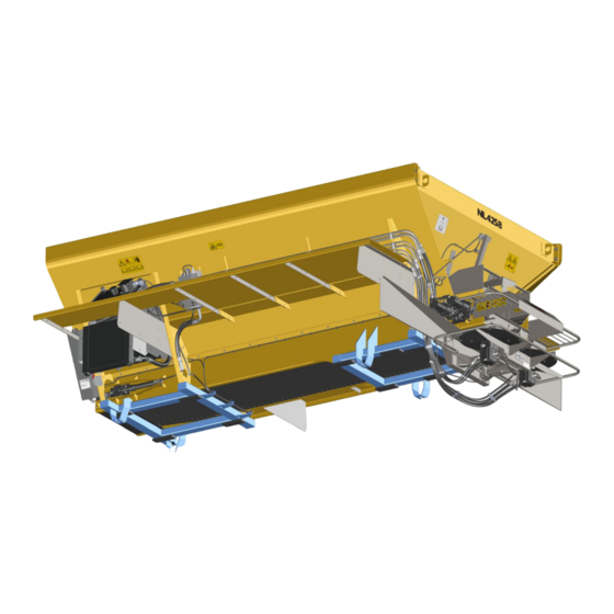
General Description Header The AGCO NL4258G4 and NL4330G4 EDGE are hopper type spreaders intended for spreading free fl owing granular agricultural materials, such as chemical fertilizers, agricultural limestone, and gypsum. They are intended for mounting on the AGCO RoGator - a high-clearance post-emergence application vehicle. -
Page 38: Introduction
NL4258/4330G4 EDGE Introduction Header Spinner REAR VIEW FRONT VIEW RIGHT HAND SIDE VIEW Spinner LEFT HAND SIDE VIEW 312521-AA-C www.New-Leader.com - 38 - (800) 363-1771... - Page 39 NL4258/4330G4 EDGE Introduction Header Bin 1: Main holding bin for material or Insert. MultApplier and MultiBin inserts (shown on following pages) are confi gured as Bins 2-4 depending on type used. Conveyor: Conveys material to rear of unit. Cross Tubes: Supports body, attaches to Chassis frame. Transfers weight from Main Hopper to Chassis. Enclosure: Houses spreader control modules, protects them from the elements Feedgate: Adjustable gate mounted into Rear Endgate.
- Page 40 NL4258/4330G4 EDGE Introduction Header MultApplier Bin 1 Bin 1 Bin 2 Bin 2 312521-AA-C www.New-Leader.com - 40 - (800) 363-1771...
- Page 41 NL4258/4330G4 EDGE Dimensions & Capacities Header Single Bin 162.76 " 163” (4140mm) 132.10 " 132” (3353mm) (INSIDE) 126” 125.99 " (3200mm) SINGLE BIN WEIGHTS & CAPACITIES Overall Approximate Unit Top Width Struck Capacity Model Height Weight Length Cu Ft (Cu M) Lbs (Kg) 120”...
-
Page 42: Dimensions & Capacities
NL4258/4330G4 EDGE Dimensions & Capacities Header With MultApplier 163” (4140mm) 132” (3353mm) 132.10 " (INSIDE) 60.10 " 60” (1524mm) (INSIDE) WITH MULTAPPLIER WEIGHTS & CAPACITIES With 5’ (1.5m) MultApplier Approximate Bin 1 Struck Model Unit Length Weight Capacity Lbs (Kg) Cu ft (Cu M) NL4258G4 4800 (2177) - Page 43 NL4258/4330G4 EDGE Dimensions & Capacities Header With MultApplier A (INSIDE) MultApplier Alone Dimensions & Capacities 5’ (1.5m) MultApplier Model NL4258G4 NL4330G4 Inside Length 60” (1524mm) Overall Length 77” (1956mm) Overall Height 46” (1168mm) 51” (1295mm) Top Width 120” (3048mm) 121” (3073mm) Approximate Weight 1100 (499) 1200 (544)
-
Page 44: Initial Start-Up
NL4258/4330G4 EDGE Initial Start-Up Header Stand clear of moving machinery. WARNING NOTE: Do not load spreader with material. 1. Check entire unit to make sure all fasteners are in place and properly tightened per “Standard Torques” section in this manual. 2. -
Page 45: General Operating Procedures
NL4258/4330G4 EDGE General Operating Procedures Header 1. Make sure unit has been properly serviced and is in good operating condition. It is recommended to run the spreader prior to loading material to ensure acceptable operation. 2. Set manual machine settings in controller per Controller section in this manual. 3. - Page 46 NL4258/4330G4 EDGE Notes This page is intentionally left blank. 312521-AA-C www.New-Leader.com - 46 - (800) 363-1771...
-
Page 47: Lubrication & Maintenance
NL4258/4330G4 EDGE Lubrication & Maintenance Header PREVENTATIVE MAINTENANCE PAYS! The handling and spreading of commercial fertilizers is a most severe operation with respect to metal corrosion. Establish a frequent, periodic preventative maintenance program to prevent rapid damage to spreading equipment. Proper cleaning, lubrication and maintenance will give you longer life, more satisfactory service and more economical use of your equipment. -
Page 48: Hydraulic Hose
NL4258/4330G4 EDGE Lubrication & Maintenance Header HYDRAULIC HOSE Hose assemblies in operation should be inspected frequently for leakage, kinking, abrasion, corrosion or other signs of wear or damage. Worn or damaged hose assemblies should be replaced immediately. When replacing, use hoses of same or better rating and construction. Testing should be conducted in approved test stands with adequate guards to protect the WARNING operator. - Page 49 NL4258/4330G4 EDGE Lubrication & Maintenance Header The conveyor will move away from the bottom panel if material accumulates under the conveyor or on the sprockets. The more material that accumulates, the closer the chain will come to the chain NOTICE! shields.
-
Page 50: Conveyor Belt Maintenance
NL4258/4330G4 EDGE Lubrication & Maintenance Header REAR OF UNIT Proper Tension Main Bin Conveyor 36” to 40” (9144mm - 1016mm) Bin 2 Conveyor 30” to 34” (76c2mm - 864mm) 36” - 40” (9144mm - 1016mm) MAIN BIN 30” - 34” (762mm - 864mm) INSERT BIN 2 CONVEYOR BELT MAINTENANCE Standard belt for the #4 chain is moderate oil resistant that is impervious to moisture, weathering, or normal action which can be used with chemical impregnated fertilizer or oil based additives. -
Page 51: Spinner Fins
NL4258/4330G4 EDGE Lubrication & Maintenance Header SPINNER FINS Visually inspect spinner fi ns (Figure 4) daily for build-up of material and wear. Spinner discs and fi ns must be kept clean and polished. Even a small build-up of material on a spinner can signifi... -
Page 52: Conveyor Gearcase
NL4258/4330G4 EDGE Lubrication & Maintenance Header CONVEYOR GEARCASE Drain oil in a new unit after fi rst two weeks (or not more than 100 hours) of operation, and fl ush gear case thoroughly with light oil. Refer to “Lubricant and Hydraulic Oil Specifi cations” section for proper grade oil and recommended amounts of lubricant. -
Page 53: Lubricant & Oil Specifi Cations
fl uid’s specifi cations in the table below are for normal operating conditions. Extreme environments or dirty conditions may require the use of different oils. Consult your New Leader dealer or the Product Support Department at Highway Equipment Company for systems operating outside normal conditions. -
Page 54: Lubrication & Maintenance Chart
NL4258/4330G4 EDGE Header Lubrication & Maintenance Chart Shut off all power and allow all moving parts to come to rest before performing any WARNING maintenance operation. The spreader should be regularly lubricated with the lubricants recommended in this manual in accordance with the following chart: Location Places... - Page 55 NL4258/4330G4 EDGE Header Lubrication & Maintenance Chart FRONT BANK REAR BANK - SINGLE BIN REAR BANK - WITH INSERT Figure 7 - Spreader Grease Banks Figure 8 - Front Grease Bank Loca ons BIN 2 INSERT CONVEYOR Figure 9 - Rear Grease Bank Loca ons www.New-Leader.com 312521-AA-C - 55 -...
-
Page 56: Troubleshooting
NL4258/4330G4 EDGE Troubleshooting Header Symptom: Reason: Correction: Spinner will not run Defective Spinner Control Valve Replace spinner control valve cartridge and coil. No voltage at valve Verify spinner switch is on. Verify spinner enable is checked. Verify controller has a target spinner RPM entered. Check WSM 7.5 amp fuse is not blown. - Page 57 NL4258/4330G4 EDGE Troubleshooting Header Symptom: Reason: Correction: Conveyor will not shut off Defective conveyor cartridge Replace conveyor control valve cartridge. Control valve is out of time Adjust cartridge timing. Conveyor runs erratic Defective conveyor cartridge Replace conveyor control valve cartridge. Encoder failure Replace encoder.
-
Page 58: Spreader Module Led Light Alerts
NL4258/4330G4 EDGE Troubleshooting Header SPREADER MODULE LED LIGHT ALERTS Power LED Flashing Solid Flashing Solid Flasing Solid Red Amber Amber Green Green • • • • • • • • • • • • • • • Boot No App Running Upgrage Running... -
Page 59: Standard Torques
NL4258/4330G4 EDGE Standard Torques Header CAP SCREW GRADE IDENTIFICATION - MARKINGS ON HEAD NO MARKINGS GRADE 2 THREE MARKS - 120 DEGREES APART GRADE 5 SIX MARKS - 60 DEGREES APART GRADE 8 USE GRADE 2 TORQUES FOR STAINLESS STEEL FASTENERS AND CARRIAGE BOLTS. TORQUE - FOOT-POUNDS CAP SCREW GRADE 2... -
Page 60: Pre- And Post-Season Checklist
NL4258/4330G4 EDGE Pre- and Post-Season Checklist Header Do not operate or work on machine without reading and understanding the operator’s IMPORTANT! manual. Before starting engine/before starting machine operation Program rate controller and document settings Hydraulic hoses are secured properly All stop, tail, and turn lights function properly Gearcase oil level is correct Tire pressures are equal on each side of chassis All guards and shields in place... - Page 61 NL4258/4330G4 EDGE Hydraulics Header The following pages contain representative hydraulic schematics for the NL4330G4 EDGE model spreader. Hydraulic Components Spinner Motor Hydraulic Reservoir Valve Block - Face Valve Block - Rear (cut-away) www.New-Leader.com 312521-AA-C - 61 - (800) 363-1771...
- Page 62 NL4258/4330G4 EDGE New Leader Hydraulic Schematic - NL4258G4 Header Single Bin 312521-AA-C www.New-Leader.com - 62 - (800) 363-1771...
- Page 63 NL4258/4330G4 EDGE Flow Diagram - NL4258G4 Header Single Bin www.New-Leader.com 312521-AA-C - 63 - (800) 363-1771...
- Page 64 NL4258/4330G4 EDGE New Leader Hydraulic Schematic - NL4258G4 Header MultApplier Complete 312521-AA-C www.New-Leader.com - 64 - (800) 363-1771...
- Page 65 NL4258/4330G4 EDGE Flow Diagram - NL4258G4 Header MultApplier Complete www.New-Leader.com 312521-AA-C - 65 - (800) 363-1771...
- Page 66 NL4258/4330G4 EDGE New Leader Hydraulic Schematic - NL4330G4 Header Single Bin 312521-AA-C www.New-Leader.com - 66 - (800) 363-1771...
- Page 67 NL4258/4330G4 EDGE Flow Diagram - NL4330G4 Header Single Bin www.New-Leader.com 312521-AA-C - 67 - (800) 363-1771...
- Page 68 NL4258/4330G4 EDGE New Leader Hydraulic Schematic - NL4330G4 Header MultApplier Complete 312521-AA-C www.New-Leader.com - 68 - (800) 363-1771...
- Page 69 NL4258/4330G4 EDGE Header Flow Diagram - NL4330G4 MultApplier Complete www.New-Leader.com 312521-AA-C - 69 - (800) 363-1771...
- Page 70 NL4258/4330G4 EDGE Notes This page is intentionally left blank. 312521-AA-C www.New-Leader.com - 70 - (800) 363-1771...
-
Page 71: Controller Operations
UI (User Interface) - The displayed information and controls the user interacts with on the Display Monitor to make any necessary changes to implement performance. • ECU (Electronic Control Unit) - New Leader module that controls specifi c functions of the implement and is attached to the BUS. •... -
Page 72: Cab To Enclosure Diagram
NL4258/4330G4 EDGE Header Controller Operations Cab to Enclosure Diagram 312521-AA-C www.New-Leader.com - 72 - (800) 363-1771... -
Page 73: Modules To Function Diagram
NL4258/4330G4 EDGE Header Controller Operations Modules to Function Diagram Conveyor Conveyor Pressure Speed Conveyor Control Sensor Conveyor Pressure Conveyor Speed Conveyor Control Sensor Main Hydraulic Conveyor Spinner 1 Spinner 1 Hydraulic Speed Control Level Filter Speed Pressure Hydraulic Conveyor Conveyor Chain Spinner 2 Spinner 2... -
Page 74: Requirements
Header Controller Operations Requirements System Requirements: Function: • Virtual Terminal version 3 that supports • VT will load New Leader UI and assign AUX-N functionality functions to in-cab switches. • Task Control (Multi-product up to 4 bins) • TC-BAS •... -
Page 75: Navigation
Header Controller Operations Navigation To activate the New Leader Controller Interface, power up the monitor and activate the VT settings. For instructions on how to activate the VT, see the Manufacturer’s Operations Manual for the specifi c monitor being used. -
Page 76: Navigation Control Buttons
NL4258/4330G4 EDGE Header Controller Operations An on-screen Numeric Keypad is made available for changing confi guration settings and calibration numbers. Press the keypad button to access the on-screen numeric entry screen. Keypads may look different depending on VT being used. Figure 3 - Numeric Keypad Navigation Control Buttons Back Button... -
Page 77: Machine Confi Guration
NL4258/4330G4 EDGE Header Controller Operations Machine Confi guration NOTE: Refer to default settings table at end of controller section for factory setup defaults. Before use, Display Monitor must be setup to enable VT connection and a machine confi guration NOTE: may need to be built. -
Page 78: Enable Installed Bins
NL4258/4330G4 EDGE Header Controller Operations Enable Installed Bins • Enable all bins that are installed on the unit by pressing the button next to each. A will appear next to enabled bins as shown. Press to continue. Bin Settings Bin settings include Name, Capacity, Bin Sensor, Feedgate enabled/disabled, Pressure... - Page 79 NL4258/4330G4 EDGE Header Controller Operations • Repeat step 3 for MultiBin Micro 1 as necessary. Press to continue. • Repeat step 3 for MultiBin Micro 2 as necessary. Press to continue. www.New-Leader.com 312521-AA-C - 79 - (800) 363-1771...
-
Page 80: Gps Offsets
NL4258/4330G4 EDGE Header Controller Operations GPS Offsets Editing the task controller GPS offset settings will determine drop point of material behind chassis. • Select Towed or Self Propelled and enter GPS Offset using keypad. Towed • For single axle towed units, enter the distance from the center of the hitch pin to the center of the axle (a). -
Page 81: Settings
NL4258/4330G4 EDGE Header Controller Operations Settings Changing machine calibrations allows operator to enable/disable bins, adjust valve calibration numbers, change alarm settings and reset modules. On the Home Screen, press to change these settings: Press to to enable/disable bins. Enable/Disable Bins •... - Page 82 NL4258/4330G4 EDGE Header Controller Operations • Press to set spinners. Enter appropriate settings: • PWM Valve settings: • “Monitor” - no PWM control • “Control” - tries to maintain spinner speed at all times regardless of available hydraulic fl ow. Best for hydrostatic or CVT drives.
-
Page 83: Alarm Settings
NL4258/4330G4 EDGE Header Controller Operations Enter appropriate settings: • Valve Response 1 - Determines speed of servo valve when product control error exceeds Response Threshold setting. Represents fast speed of servo valve. Decreasing value will cause servo valve to run slower. Default setting is 40%. •... -
Page 84: Reconfi Gure System
Pressing “Reset” under “System Settings will restore all settings to factory default and all NOTICE! calibration numbers will be lost. It should only be pressed if instructed to do so by service technician or New Leader product support. • Press to reset/reconfi... -
Page 85: Switch Assignment
• Press to show connected devices. • Connected devices will appear in the device list. • If using a New Leader switch box, press to automatically map the switches to the correct function. www.New-Leader.com 312521-AA-C - 85 - (800) 363-1771... -
Page 86: Material Profi Le Management
NL4258/4330G4 EDGE Header Controller Operations Material Profi le Management For every material to be spread, at every unique rate, a material profi le must be confi gured. On the Home Screen, press to manage profi les. Spread pattern testing is required when creating a new profi le or if modifying an existing profi le. NOTE: A spread pattern test kit is available for this purpose. -
Page 87: Creating A New Profi Le
NL4258/4330G4 EDGE Header Controller Operations Creating a New Profi le When creating a new profi le for a new material to be spread, spread pattern tests must be NOTE: conducted. Spread pattern testing at low and average application rates ensures proper spinner position for given spreader output. - Page 88 NL4258/4330G4 EDGE Header Controller Operations • Enter the minimum rate to be used for Min Rate. • Enter the average between the minimum rate and maximum rate to be used for Avg Rate. • Repeat for each active bin. Feedgate Optimizer will suggest a new NOTE: gate height if desired application rate is not possible with current gate height.
- Page 89 NL4258/4330G4 EDGE Header Controller Operations • Enter starting spinner speed, spinner assembly fore/aft scale position and desired swath width. • Turn on spinners and drive through the test course. • Collect and analyze spread pattern test results from pans. • Make adjustments and repeat test as necessary to achieve desired results.
- Page 90 NL4258/4330G4 EDGE Header Controller Operations • Press the dropdown arrow to select desired profi le. • Select desired profi le from the dropdown list. • Press to set selected profi le. • Press • Active profi le is displayed below the swath display below Spinner Settings on the Run Screen.
- Page 91 NL4258/4330G4 EDGE Controller Operations Notes This page is intentionally left blank. www.New-Leader.com 312521-AA-C - 91 - (800) 363-1771...
-
Page 92: Component Calibration
NL4258/4330G4 EDGE Header Controller Operations Component Calibration NOTE: Before regular use, system must be calibrated to ensure accurate spreading. • Power up Display Monitor and activate VT. • The Run screen will appear. Press to continue. Spinner Disc Calibration • Press to calibrate spinner discs. -
Page 93: Spinner Assembly Calibration
NL4258/4330G4 EDGE Header Controller Operations Spinner Assembly Calibration The spinner assembly must be calibrated if either the fore/aft or left right cylinders are replaced, or if a new swath module is installed. • Press to calibrate spinner assembly. Spinner assembly will move during WARNING calibration process. -
Page 94: Feedgate Calibration
NL4258/4330G4 EDGE Header Controller Operations Feedgate Calibration 1. Press to calibrate feedgate height. 2. List will appear with all installed feedgates. Select feedgate to calibrate. 3. The feedgate will move to its lowest possible height. Press to continue. 4. Measure the actual height of the feedgate above the conveyor as shown by measurement A. - Page 95 NL4258/4330G4 EDGE Header Controller Operations 5. Enter the actual measured height of the feedgate in the display. Press to continue. 6. The feedgate will now move to its maximum height. Press to continue. 7. Measure the actual height of the feedgate from the conveyor as shown by measurement B.
- Page 96 NL4258/4330G4 EDGE Header Controller Operations 9. Measure the height of the actual feedgate opening from the conveyor as shown by measurement C. 10. Enter the measured height of the feedgate opening into the display. Press to continue. 11. Repeat steps 2 - 10 for all installed feedgates. 312521-AA-C www.New-Leader.com - 96 -...
-
Page 97: Conveyor Calibration
NL4258/4330G4 EDGE Header Controller Operations Conveyor Calibration For best results, a catch test must be done for each product to be spread before season begins, or any time a new supply of product is received. • Press to calibrate conveyor. •... - Page 98 NL4258/4330G4 EDGE Header Controller Operations • Using the control buttons (Reset, Run, Stop), run a catch test. If spreading product that has already been tested, press to continue. To begin a test, press . Conveyor will run. • Once controller dispenses specifi c amount, conveyor will stop.
- Page 99 NL4258/4330G4 EDGE Header Controller Operations • After dispensing product in fi eld, screen displays system perceived total of dispensed product. To enter actual dispensed amount, press • Using keypad, enter actual weight of product dispensed. Press to continue. • New cubic feet per revolution (CFR) rate will be displayed.
-
Page 100: Operations/Features
NL4258/4330G4 EDGE Header Controller Operations Operations/Features Create New Job The following is a guide for running system for fi rst time. 1. Create Job in display. This operation will vary from display to display. Refer to display manual on how to create a job using Task Control. - Page 101 NL4258/4330G4 EDGE Header Controller Operations 3. Verify task control in Target Rate 1. • Rate will be driven by job setup in display. To verify this, TC should show in place of target rate 1. If not, verify job has been created correctly. Refer to display manual.
- Page 102 NL4258/4330G4 EDGE Header Controller Operations • Use keypad to set feedgate opening to correct reading. 6. Verify CFR number is correct: Different products may require different calibration numbers. Verify the CFR number is correct before applying product. • Press then •...
-
Page 103: Feedgate Optimizer
NL4258/4330G4 EDGE Header Controller Operations Feedgate Optimizer This program will help to determine the ideal gate position for each specifi c application, based on NOTE: speed, swath width, density, and application rate. 1. Power up Display Monitor and activate VT. •... -
Page 104: Boundary Spreading
NL4258/4330G4 EDGE Header Controller Operations Boundary Spreading This program allows the operator to independently modify spinner speeds to change the width of NOTE: spread to either side, creating a “boundary” line to maximize spreading effi ciency. • On the Run Screen, press to access spinner settings. -
Page 105: Remote Spreading
NL4258/4330G4 EDGE Header Controller Operations Remote Spreading This program allows the operator to shift the spinner assembly left or right to apply a near “half NOTE: pattern” with the majority of the pattern on one side of the machine only. •... -
Page 106: Diagnostics
NL4258/4330G4 EDGE Header Controller Operations Diagnostics Advanced diagnostic features are available that allow the operator to quickly diagnose most issues NOTE: that could occur. 1. Power up Display Monitor and activate VT. • The Run screen will appear. Press continue. •... - Page 107 NL4258/4330G4 EDGE Header Controller Operations • To view machine lifetimes totals, press • At top of screen, each bin’s lifetime totals for acres and weight appears. At bottom of screen, cumulative Acres(ac) and Weight(lbs) will appear. Hours(hrs) will be on main bin only. Press to return to Diagnostics screen.
- Page 108 NL4258/4330G4 EDGE Header Controller Operations • To view unlocked features, press • Current unlocked features will display. Press “Unlock” to display module serial number and registration number. Press to return. 312521-AA-C www.New-Leader.com - 108 - (800) 363-1771...
-
Page 109: Hydraulics
NL4258/4330G4 EDGE Header Controller Operations Hydraulics This program will show a visual representation of hydraulic monitoring, including system pressure, NOTE: temperature, conveyor pressure, and indicators for low fl uid level and fi lter restriction. Individual bins can be viewed by pressing the bin icons along the bottom of the screen. 1. -
Page 110: Cylinder Bleeding
NL4258/4330G4 EDGE Header Controller Operations Cylinder Bleeding Bleeding routine is run to purge air from hydraulic cylinders for accurate positioning. Perform the bleeding routine at the beginning of each season, after any service work has been performed on the hydrauilc system, and upon startup if spreader has been sitting for an extended period of time. •... -
Page 111: Bin Flush
NL4258/4330G4 EDGE Header Controller Operations Bin Flush This program is used to quickly empty each bin. Spinners will automatically shut off and allow the NOTE: operator to select which bins to empty. 1. Power up Display Monitor and activate VT. •... - Page 112 NL4258/4330G4 EDGE Header Controller Operations 2. Select bins: • Select bins to be fl ushed by pressing enable buttons next to each. To adjust conveyor RPM for fl ush, press 3. Set conveyor RPM: • Use keypads to set conveyor RPM for each bin. 20 RPM is default.
-
Page 113: Body Module
NL4258/4330G4 EDGE Header Controller Operations Body Module 1. Power up Display Monitor and activate VT. • The Run screen will appear. Press to continue. • The Tools main screen will appear. Press to continue. Bin Cover Control • If equipped, press (A) to open and close tarp. -
Page 114: Chain Oiler
NL4258/4330G4 EDGE Header Controller Operations Chain Oiler NOTE: This program is used to manually oil the chain, set alarm frequency, and set auto-lube settings. 1. Power up Display Monitor and activate VT. • The Run screen will appear. Press to continue. •... - Page 115 NL4258/4330G4 EDGE Header Controller Operations 3. Set conveyor dimensions: • Press “Dimensions” to input conveyor dimensions. Use keypads to input conveyor length and sprocket diameter. Press to return to Chain Oiler screen. Press to return to Tools Screen. 4. Set service reminder: •...
-
Page 116: Bin Sequencing
NL4258/4330G4 EDGE Header Controller Operations Bin Sequencing This function allows the operator to run same product out of two bins, chaining them together so NOTE: bin 2 starts emptying immediately after bin 1 is empty. 1. Power up Display Monitor and activate VT. •... - Page 117 NL4258/4330G4 EDGE Header Controller Operations 2. Setup Bin Sequencing (Chaining): A. Enable bin chaining for Bins 1 & 2, or Bins 3 & 4 as applicable. B. Select trigger type (Manual Only, Low Bin Threshold, Low Bin Sensor, Container Reaches 0). C.
-
Page 118: General Alarms
NL4258/4330G4 EDGE Header Controller Operations General Alarms Alarm Title Description WSM Spreader Local CAN Bus Error Check the local CAN bus connection. Module WSM Spreader The module software reset due to an Module Software Reset Module unhandled error. WSM Spreader Local CAN Bus Warning Check the local CAN bus connection. -
Page 119: General Product Control Alarms
NL4258/4330G4 EDGE Header Controller Operations General Product Control Alarms Alarm Description Trigger “Calibration error, lost or intermittent Rate sensor signal is lost for a period Rate sensor error signal from rate sensor. Check sensor of two or more consecutive seconds during calibration and related wiring prior to calibrating during the Static Conveyor Calibration... -
Page 120: Spinner Alarms
NL4258/4330G4 EDGE Header Controller Operations Spinner Alarms Alarm Description Trigger Automatic control for spinners must be enabled. [CLF Mode] [Basic Single] must be selected. At least one product CLF Basic Single bin must be commanded on. Perceived Spinners Not “Spinners Not Responding” spinner speed is greater than 30 rpm in Responding error from [Target Spinner Speed] for a... -
Page 121: Fan Frame Alarms
NL4258/4330G4 EDGE Header Controller Operations Fan Frame Alarms Alarm Description Trigger [Fan Frame Enable/Disable] is Enabled, Fan Frame Not “Fan Frame must be calibrated prior to equipment profi le is active and Fan Calibrated operation.” + [Sensor Name] Frame position sensor has not been calibrated. -
Page 122: Feed Gate Alarms
NL4258/4330G4 EDGE Header Controller Operations Feed Gate Alarms Alarm Description Trigger [Feed Gate Enable/Disable] is Enabled, Feed Gate Not “Feed Gate must be calibrated prior to equipment profi le is active and feed Calibrated operation.” + [Bin Name] gate actuator has not been calibrated. Upon user acknowledgement, dialog “Feed Gate may move at this time. -
Page 123: Hydraulic Alarms
NL4258/4330G4 EDGE Header Controller Operations Hydraulic Alarms Alarm Description Trigger Conveyor Conveyor hydraulic pressure exceeds Hydraulic “Conveyor Hydraulic Pressure Exceeds [Max Conveyor Hydraulics Pressure] Pressure Exceeds Maximum Operating Range.” setting for a period of fi ve consecutive Maximum seconds or longer. System hydraulic pressure exceeds [Max System Hydraulic “System Hydraulic Pressure Exceeds... -
Page 124: Default Settings
NL4258/4330G4 EDGE Header Controller Operations Default Settings NOTE: Compatible Insert Bin confi gurations vary per model. See “General Description” in Operations section of this manual for details. Refer to “Dimensions & Capacities” in Operations section of this manual for capacities on all applicable bin confi... -
Page 125: Calibration
NL4258/4330G4 EDGE Header Controller Operations Calibration CFR Values Value Main Bin 0.256 Insert Bin 0.144 Yellow Micro Bin 0.038 Red Micro Bin 0.019 Control Valve Settings Control Valve Control Variable Main Insert Micro 1 Micro 2 Control Valve Type Servo Servo Servo Servo... - Page 126 NL4258/4330G4 EDGE Notes This page is intentionally left blank. 312521-AA-C www.New-Leader.com - 126 - (800) 363-1771...
-
Page 127: Spread Pattern
Spread Pattern Header The following informa on will guide you through using the SGN & Crush Strength Test Kit for your New Leader G4 Spreader. Refer to operator’s manual for details on unit safety, opera on and maintenance. PART NUMBER... -
Page 128: Product Setup Guidelines
NL4258/4330G4 EDGE Spread Pattern Header NOTE: SGN and Crush Strength together determine spread width. General Rules: A small product with low crush strength will have limited spread width capabili es. Spinner RPM must remain lower to keep from pulverizing the so product, limi ng your overall spread width. Addi onally, a smaller product has less mass than that of a larger product, and in this case is another limi ng factor for overall spread width. -
Page 129: Crush Test
Crushing strength can signifi cantly increase with par cle size. 1. Figure 1 - Place individual granule on solid, smooth surface. 2. Place New Leader crush strength tester over granule, open end fl ush with surface. Ensure marker is next to handle. -
Page 130: Sgn Scale Test
NL4258/4330G4 EDGE Spread Pattern Header SGN SCALE TEST The SGN scale is an instrument designed for simple screen test of fer lizer samples. A small box fi ed with fi ve sieves, it directly produces a size histogram of the test sample. From this, the SGN can be es mated. 1. - Page 131 NL4258/4330G4 EDGE Spread Pattern Header 7. Figure 7 - Based on column headings and percent in each fi eld, calculate overall SGN of the sample. Size Grade Number View each column for percentage • Column A (120) = 0 material •...
-
Page 132: Catch Test
NOTE: An op onal calibra on chute (P/N 312688) is available to simplify the catch test process. The calibra on chute fi ts all New Leader spreader models with 30” wide conveyor bo oms. Contact your local New Leader dealer for details. -
Page 133: Spread Pattern Test Kit
NL4258/4330G4 EDGE Spread Pattern Header Use great caution while working around the spreader. Contact with spinners and WARNING other moving parts is very dangerous. Do not adjust while machinery is moving, wear eye protection and avoid discharge from spinners. Do not ride on moving spreader. Spinner assembly and material divider have NOT been adjusted at the factory. -
Page 134: Spinners
NL4258/4330G4 EDGE Spread Pattern Header SPINNERS Spinner discs and fi ns must be kept clean and polished. Even a small build-up on a spinner fi n can NOTICE! signifi cantly affect the spread pattern. Rusty, rough, bent or worn fi ns will produce poor spread patterns. -
Page 135: Test Procedure
NL4258/4330G4 EDGE Spread Pattern Header SPINNER FRAME SETTING SPINNER MATERIAL in (cm) Lime 1 (2.5) Straight Urea 3.5 (9.5) All other Fertilizer types and blends, including Urea 3.5 (9.5) blends TEST PROCEDURE Using the data sheets supplied with the kit, document all spreader information and adjustments as necessary. - Page 136 NL4258/4330G4 EDGE Spread Pattern Header Four-Wheeled Vehicles 60’ 60’ For four-wheeled application vehicles, position the spreader at the beginning of the course so that the vehicle will straddle the center collection tray. See Figure 100’ 75’ 20’ (3m) Engage spinners before navigating the course. As the 10’...
-
Page 137: Test Results
NL4258/4330G4 EDGE Spread Pattern Header TEST RESULTS After navigating the course, shut the spreader down and park in a secure location. Using the funnel, transfer the contents of each collection tray into its corresponding test tube beginning at one end of the trays and working towards the opposite end. If spreading a blend of materials, inspect all tubes to determine if the blend is consistent across the entire swath width. -
Page 138: Determining Driving Centers
NL4258/4330G4 EDGE Spread Pattern Header DETERMINING DRIVING CENTERS Once an acceptable pattern is obtained, as shown in Figure 12, driving centers can be determined. To determine optimum driving centers (effective swath width), determine the average amount of material in the center of the pattern. Figure 13 shows an example data sheet recorded from the profi le shown in Figure 14. -
Page 139: Troubleshooting
NL4258/4330G4 EDGE Spread Pattern Header TROUBLESHOOTING NOTE: It is highly recommended that ONLY ONE ADJUSTMENT be made between test samples taken. If more than one adjustment is made, it will be diffi cult to determine which adjustment was responsible for the change in pattern shape. -
Page 140: Verifying Driving Centers
NL4258/4330G4 EDGE Spread Pattern Header VERIFYING DRIVING CENTERS Once optimum driving centers (effective swath width) have been established, conduct a fi nal “S” pass over the trays to verify. Refer to Figure 9. 1. With both the spinners and conveyor turned off, drive the spreader through the center of the course, establishing an “AB”...
Need help?
Do you have a question about the AGCO NL4258G4 and is the answer not in the manual?
Questions and answers