Table of Contents
Advertisement
Quick Links
HIGHWAY EQUIPMENT COMPANY
GENERAL MANUAL FOR MODEL
L3020
G4
SAFETY GUIDELINES
INSTALLATION
OPERATION
Dealer Sticker
MAINTENANCE
TROUBLESHOOTING
PARTS LIST
This unit may have been built with
_________________
SPECIAL FEATURES.
Provide
SERIAL NO.
SERIAL NUMBER when ordering
parts.
IMPORTANT: READ THE SAFETY GUIDELINES AND ALL INSTRUCTIONS CAREFULLY BEFORE OPERATING
HIGHWAY EQUIPMENT COMPANY – NEW LEADER DIVISION
1330 76TH AVE SW, CEDAR RAPIDS, IOWA 52404-7052
PH. (319) 363-8281
www.highwayequipment.com
FAX (319) 632-3081
Advertisement
Chapters
Table of Contents

Related Manuals for New Leader L3020G4


Summary of Contents for New Leader L3020G4
- Page 1 SERIAL NO. SERIAL NUMBER when ordering parts. IMPORTANT: READ THE SAFETY GUIDELINES AND ALL INSTRUCTIONS CAREFULLY BEFORE OPERATING HIGHWAY EQUIPMENT COMPANY – NEW LEADER DIVISION 1330 76TH AVE SW, CEDAR RAPIDS, IOWA 52404-7052 PH. (319) 363-8281 www.highwayequipment.com FAX (319) 632-3081...
- Page 3 MODEL L3020G4 UNIT SERIAL NUMBER__________________ MANUAL NUMBER: 97372-B EFFECTIVE: 6/2006 Starting with Serial No. 122208 HIGHWAY EQUIPMENT COMPANY 1330 76 AVE SW CEDAR RAPIDS, IOWA 52404-7052 PHONE (319) 363-8281 FAX (319) 632-3081 www.highwayequipment.com BUILDING THE BEST SINCE 1939 Copyright 2003 Highway Equipment Company, Inc.
-
Page 4: Table Of Contents
HIGHWAY EQUIPMENT COMPANY TABLE OF CONTENTS Warranty ....................4 Preface .....................5 Safety .......................6 Safety Decal Installation and Maintenance..........8 Safety Decal Illustrations ................9 General Description .................17 Dimensions & Capacities ...............18 Installation Instructions................19 Pump & PTO Requirements............... 19 Truck Requirements ................... 20 Hydraulic Pump Installation............... - Page 5 HIGHWAY EQUIPMENT COMPANY TABLE OF CONTENTS CONTINUED Torque Chart....................44 Instructions for Ordering Parts ..............45 Legend for Parts List Symbols..............45 Parts List Mounting Angles ................46 Swinging Rear Endgate ..............47 Feedgate and Jack ................48 Conveyor Chain ................50 Chain Shields ..................52 Conveyor Idler ..................54 Conveyor Drive .................55 Encoder ....................56 Conveyor Chain Oiler ...............57...
-
Page 6: Warranty
INSERT NEW LEADER (NL) WARRANTY... - Page 7 SAFETY...
- Page 8 HIGHWAY EQUIPMENT COMPANY PREFACE PLEASE ! ALWAYS THINK SAFETY FIRST !! The purpose of this manual is to familiarize the person (or persons) using this unit with the information necessary to properly install, operate, and maintain this system. These instructions cannot replace the following: the fundamental knowledge that must be possessed by the installer or operator, the knowledge of a qualified person, or the clear thinking necessary to install and operate this equipment.
-
Page 9: Preface
HIGHWAY EQUIPMENT COMPANY SAFETY TAKE NOTE! THIS SAFETY ALERT SYMBOL FOUND THROUGHOUT THIS MANUAL IS USED TO CALL YOUR ATTENTION TO INSTRUCTIONS INVOLVING YOUR PERSONAL SAFETY AND THAT OF OTHERS. FAILURE TO FOLLOW THESE INSTRUCTIONS CAN RESULT IN INJURY OR DEATH. In this manual and on the safety signs placed on the unit, the words “DANGER,”... -
Page 10: Safety
HIGHWAY EQUIPMENT COMPANY SAFETY AVOID ACCIDENTS Most accidents, whether they occur in industry, on the farm, at home, or on the highway, are caused by the failure of some individual to follow simple and fundamental safety rules or precautions. For this reason, most accidents can be prevented by recognizing the real cause and doing something about it before the accident occurs. - Page 11 HIGHWAY EQUIPMENT COMPANY SAFETY DECALS MAINTENANCE INSTRUCTIONS 1. Keep safety decals and signs clean and legible at all times. 2. Replace safety decals and signs that are missing or have become illegible. 3. Replaced parts that displayed a safety sign should also display the current sign. 4.
-
Page 12: Safety Decal Installation And Maintenance
HIGHWAY EQUIPMENT COMPANY SAFETY DECALS CONTINUED P l e a s e G i v e P a r t N o . , D e s c r i p t i o n a n d U n i t S e r i a l N o . 97372-B Page Rev. -
Page 13: Safety Decal Illustrations
HIGHWAY EQUIPMENT COMPANY GENERAL SAFETY RULES Operation Section 1. Before attempting to operate this unit, read and be sure you understand the operation and maintenance manual. Locate all controls and determine the use of each. Know what you are doing! 2. - Page 14 HIGHWAY EQUIPMENT COMPANY GENERAL SAFETY RULES Operation Section 8. Be careful in getting on and off this unit, especially in wet, icy, snowy or muddy conditions. Clean mud, snow or ice from steps and footwear. 9. Do not allow anyone to ride on any part of unit for any reason.
- Page 15 HIGHWAY EQUIPMENT COMPANY GENERAL SAFETY RULES Operation Section 14. Starting fluids and sprays are extremely flammable. Don’t smoke. Stay away from flame or heat! 15. All vehicles should be equipped with a serviceable fire extinguisher of 5 BC rating or larger. 16.
- Page 16 HIGHWAY EQUIPMENT COMPANY GENERAL SAFETY RULES Maintenance Section 1. Maintenance includes lubrication, inspection, adjustments (other than operational control adjustments such as feedgate openings, conveyor speed, etc.) part replacement, repairs and such upkeep tasks as cleaning and painting. 2. When performing any maintenance work, wear proper protective equipment—always wear eye protection—safety shoes can help save your toes—gloves will help protect your hands...
- Page 17 HIGHWAY EQUIPMENT COMPANY GENERAL SAFETY RULES Maintenance Section 8. If repairs require use of a torch or electric welder, be sure that all flammable and combustible materials are removed. Fuel or oil reservoirs must be emptied, steam cleaned and filled with water before attempting to cut or weld them.
- Page 18 HIGHWAY EQUIPMENT COMPANY GENERAL SAFETY RULES Installation Section 1. The selection of the vehicle on which a spreader body is to be mounted has important safety aspects. To avoid overloading: a. Do not mount spreader on a chassis which, when fully loaded with material to be spread, will exceed either the Gross Axle Weight Rating (GAWR) or the Gross...
- Page 19 HIGHWAY EQUIPMENT COMPANY GENERAL SAFETY RULES Installation Section 5. Do not weld on vehicle frame as such welding lead fatigue cracking and must be avoided. When drilling holes in frame member, drill only through the vertical web portions− do not put holes in top or bottom flanges.
- Page 20 OP & MAINT...
-
Page 21: General Description
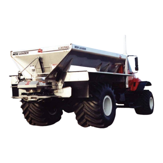
HIGHWAY EQUIPMENT COMPANY GENERAL DESCRIPTION The Model L3020G4 is a hopper type spreader intended for spreading free flowing granular agricultural materials, such as chemical fertilizers, agricultural limestone, and gypsum. It is intended for truck chassis or flotation vehicle mounting. The unit is powered hydraulically and provides independent variable speed control for the spinner and full automatic ground speed control for the conveyor by means of a motorized valve with shaft sensor or Mark series control system. -
Page 22: Dimensions & Capacities
HIGHWAY EQUIPMENT COMPANY DIMENSIONS & CAPACITIES Dimensions Cab to Axle or Cab Body Overall Inside Frame to Tandem Length CA/CT 10’ (3.05 m) 148” (376cm) 120” (305cm) 111” (282cm) 84” (213cm) CA 11’ (3.36 m) 160” (406cm) 132” (335cm) 123” (312cm) 84”... -
Page 23: Installation Instructions
6. Installation of optional parts. 7. Filling of hydraulic tanks and lubrication. 8. Checking for leaks and proper functioning. Pump and truck requirements must be determined prior to installation of the IMPORTANT! L3020G4. PUMP AND PTO REQUIREMENTS: Hydraulic Requirements Maximum Pressure: 3100 PSI Flow:... -
Page 24: Truck Requirements
TRUCK REQUIREMENTS In mounting the L3020G4 spreader on a truck, the following major questions must be considered: 1. Is the CA (Cab to Axle) dimension of the truck correct for the length of the spreader? To answer this question, see the Dimensions chart on page 20. -
Page 25: Hydraulic Pump Installation
HIGHWAY EQUIPMENT COMPANY INSTALLATION INSTRUCTIONS CONTINUED HYDRAULIC PUMP INSTALLATION A mounting bracket for the hydraulic pump is shipped with the spreader. It may be necessary to modify this bracket to fit your truck since many variable factors such as PTO make and model, muffler position, transmission make and model, etc., all affect the mounting position. -
Page 26: Mounting Spreader Body
HIGHWAY EQUIPMENT COMPANY INSTALLATION INSTRUCTIONS CONTINUED MOUNTING OF SPREADER BODY Truck Frame Length The length from the rear of the cab to the rear end of the frame should be approximately as shown on Dimensions and Capacities chart under “C”. Shorten truck frame as necessary, making sure to follow truck manufacturer’s specifications so as not to void truck warranty. - Page 27 HIGHWAY EQUIPMENT COMPANY INSTALLATION INSTRUCTIONS CONTINUED Positioning Body Use only lifting devices that meet or exceed OSHA standard 1910.184. Never exceed work load limits or lift equipment over people. Empty WARNING spreader before lifting. Loads may shift or fall if improperly supported, causing injury.
- Page 28 HIGHWAY EQUIPMENT COMPANY INSTALLATION INSTRUCTIONS CONTINUED Figure 3 - Mounting Angle Installation Installing Rear Mounting Angles Make sure drill will not puncture gas tank or harm any other obstruction CAUTION before drilling holes. DO NOT WELD ON VEHICLE FRAME! Such welding can lead to IMPORTANT! fatigue cracking and must be avoided.
-
Page 29: Spinner
HIGHWAY EQUIPMENT COMPANY INSTALLATION INSTRUCTIONS CONTINUED Securing Spreader Body to Frame Connect welders ground directly to one of the items being welded anytime an arc welder is used on the vehicle or anything connected to the vehicle. Disconnect power cable from control box! Failure to do so can result in damage to IMPORTANT! components on both the vehicle and/or spreader, in which case the warranty will... -
Page 30: Fender Installation
HIGHWAY EQUIPMENT COMPANY INSTALLATION INSTRUCTIONS CONTINUED FENDER INSTALLATION Attach fender angles to spreader body as shown in Figure 5. Use upper set of holes for full or super floatation fenders and lower set of holes for semi-float and truck chassis mount fenders. Do not tighten hardware at this time. -
Page 31: Hydraulic Hose Installation
HIGHWAY EQUIPMENT COMPANY INSTALLATION INSTRUCTIONS CONTINUED HYDRAULIC HOSE INSTALLATION If a threaded connection is tightened too tightly, the fitting or housing CAUTION into which the fitting is placed could be distorted and an unstoppable leak could occur. Determine pressure port of pump. Install pressure hose into this port as shown in Figure 8. Connect suction hose to opposite port and to tank outlet on reservoir. - Page 32 HIGHWAY EQUIPMENT COMPANY INSTALLATION INSTRUCTIONS CONTINUED Do not use one manufacturer's hose with another manufacturer's WARNING fittings. Such use will void any warranty and may cause premature burst or leak of hydraulic fluids! Severe injury and/or fire could result! Reusable Non-Skive Type Ends Step 1 Cut hose to length required using a fine tooth hacksaw or cut-off machine.
- Page 33 HIGHWAY EQUIPMENT COMPANY INSTALLATION INSTRUCTIONS CONTINUED Installation Guide WRONG RIGHT WRONG RIGHT 1. Use elbows and adapters in the installation to Install hose runs to avoid rubbing or abrasion. relieve strain on the assembly, and to provide easier Clamps are often needed to support long runs of hose or and neater installations that are accessible for to keep hose away from moving parts.
-
Page 34: Electrical Connections
HIGHWAY EQUIPMENT COMPANY INSTALLATION INSTRUCTIONS CONTINUED ELECTRICAL CONNECTIONS Connect all electrical control circuits. The supply conductors should be connected to the accessory terminal of the truck ignition switch through the fifteen amp. circuit breaker provided in the control panel. All wiring should be approved automotive insulated wire, supported adequately with insulating ties or straps, and located where it will not interfere with any control or access. -
Page 35: Initial Start-Up
HIGHWAY EQUIPMENT COMPANY INITIAL START-UP Stand clear of moving machinery. WARNING NOTE: Do not load spreader with material. 1. Check entire unit to make sure all fasteners are in place and properly tightened per “Fastener Torque Chart” in this manual. 2. -
Page 36: Field Testing
HIGHWAY EQUIPMENT COMPANY FIELD TESTING The following procedure is a guide: 1. Field test over any suitable course which allows vehicle to be driven at speeds to be used while spreading. 2. Make sure unit has been properly serviced, that oil reservoir is full and gate valve under reservoir is fully open. -
Page 37: General Operating Procedures
HIGHWAY EQUIPMENT COMPANY GENERAL OPERATING PROCEDURES 1. Make sure unit has been properly serviced and is in good operating condition. Field test unit prior to first use, prior to each spreading season's use, and following overhaul or repair work, to verify that all components and systems are functioning properly. See “Field Testing”... -
Page 38: Lubrication & Maintenance
HIGHWAY EQUIPMENT COMPANY LUBRICATION & MAINTENANCE PREVENTATIVE MAINTENANCE PAYS! The handling and spreading of commercial fertilizers is a most severe operation with respect to metal corrosion. Establish a frequent, periodic preventative maintenance program to prevent rapid damage to spreading equipment. Proper cleaning, lubrication and maintenance will give you longer life, more satisfactory service and more economical use of your equipment. -
Page 39: Hydraulic Hose
HIGHWAY EQUIPMENT COMPANY LUBRICATION & MAINTENANCE CONTINUED HYDRAULIC HOSE Hose assemblies in operation should be inspected frequently for leakage, kinking, abrasion, corrosion or any other signs of wear or damage. Worn or damaged hose assemblies should be replaced immediately. Testing should be conducted in approved test stands with adequate guards WARNING to protect the operator. -
Page 40: Conveyor Chain
HIGHWAY EQUIPMENT COMPANY LUBRICATION & MAINTENANCE CONTINUED CONVEYOR CHAIN Hose down unit and remove any material build-up on sprockets and under chain. The conveyor will move away from the bottom panel if material accumulates under the conveyor or on the sprockets. The more material that accumulates, the closer the chain will come to the chain shields. -
Page 41: Conveyor Belt Maintenance
HIGHWAY EQUIPMENT COMPANY LUBRICATION & MAINTENANCE CONTINUED CONVEYOR BELT MAINTENANCE Standard belt for the #4 conveyor has a nylon fabric that is impervious to moisture, weathering and normal action except oil. The optional high-temperature oil resistant belting is highly recommended when asphalt mix or impregnated fertilizers are going to be run through the spreader. -
Page 42: Lubrication Of Bearings
HIGHWAY EQUIPMENT COMPANY LUBRICATION & MAINTENANCE CONTINUED LUBRICATION OF BEARINGS Grease in a bearing acts to prevent excessive wear of parts, protects ball races, and balls from corrosion and aids in preventing excessive heat within the bearing. It is very important the grease maintain its proper consistency during operation. -
Page 43: Lubricant & Hydraulic Oil Specifications
The hydraulic fluid’s specifications in the table below are for normal operating conditions. Extreme environments or dirty conditions may require the use of different oils. Consult your New Leader dealer or the Product Support Department at Highway Equipment Company for systems operating outside normal conditions. -
Page 44: Lubrication & Maintenance Chart
HIGHWAY EQUIPMENT COMPANY LUBRICATION & MAINTENANCE CHART Shut off all power and allow all moving parts to come to rest before WARNING performing any maintenance operation. The spreader should be regularly lubricated with the lubricants recommended in this manual in accordance with the following chart: LOCATION PLACES... -
Page 45: Troubleshooting
HIGHWAY EQUIPMENT COMPANY TROUBLESHOOTING Symptom: Spinner motors do not turn when spinner control valve is in running position or conveyor does not run when function knob is pulled out and manually rotated. See reasons 1, 2, 3, 4, 5, 7, 8 & 9. Symptom: Spinners turn but conveyor does not run in manual mode. - Page 46 HIGHWAY EQUIPMENT COMPANY TROUBLESHOOTING CONTINUED Reason: Correction: 1. Hydraulic oil level low. Add hydraulic oil to reservoir up to “Full” mark. 2. Shut-Off valve on oil reservoir not Open valve fully by turning counter-clockwise until it stops. open. 3. Hydraulic Pump is not rotating. PTO is disengaged.
- Page 47 HIGHWAY EQUIPMENT COMPANY TROUBLESHOOTING CONTINUED Reason: Correction: 14. Defective spinner control valve. Replace valve metering spool spring. If no improvement, replace spinner control valve. 15. Cab control is for conveyor only— None required. This is a normal condition. To stop spinners, spinners run anytime vehicle engine is set spinner control valve at “O”...
-
Page 48: Torque Chart
HIGHWAY EQUIPMENT COMPANY STANDARD TORQUES NATIONAL COARSE (NC) CAP SCREWS CAP SCREW GRADE IDENTIFICATION - MARKINGS ON HEAD SAE GRADE 2 NO MARKINGS SAE GRADE 5 THREE MARKS - 120 DEGREES APART SAE GRADE 8 SIX MARKS - 60 DEGREES APART USE GRADE 2 TORQUES FOR STAINLESS STEEL FASTENERS AND CARRIAGE BOLTS. -
Page 49: Instructions For Ordering Parts
HIGHWAY EQUIPMENT COMPANY INSTRUCTIONS FOR ORDERING PARTS Order from the AUTHORIZED DEALER in your area. 1. Always give the pertinent model and serial number. 2. Give part name, part number and the quantity required. 3. Give the correct address to where the parts are to be shipped, and the carrier if there is a preference. -
Page 50: Parts List Mounting Angles
HIGHWAY EQUIPMENT COMPANY MOUNTING ANGLE ITEM PART NO. DESCRIPTION 31856 Angle – Mounting 20131 Cap Screw – 1/2 x 2 20695 Washer – Flat 1/2 20680 Nut – Lock 1/2 81847 Angle – Mounting 81000 Spring 81848 Mounting – Bar 41762 Nut –... -
Page 51: Swinging Rear Endgate
HIGHWAY EQUIPMENT COMPANY SWINGING REAR ENDGATE ITEM PART NO. DESCRIPTION 82963 Endgate – Rear Weldment 36719 Pin – Clevis 20828 Pin – Cotter 72247 Tube Weldment 83512 Pivot – Short Weldment 36727 Shaft – Pivot Weldment 83513 Pivot – Long Weldment 36899 Handle 21027... -
Page 52: Feedgate And Jack
HIGHWAY EQUIPMENT COMPANY FEEDGATE AND JACK 10,11 12,13,14 JACK P l e a s e G i v e P a r t N o . , D e s c r i p t i o n a n d U n i t S e r i a l N o . 97372-B Page Rev. - Page 53 HIGHWAY EQUIPMENT COMPANY FEEDGATE AND JACK CONTINUED ITEM PART NO. DESCRIPTION 409 SS 304 SS 2885 36384 36384 Slide – Feedgate RH 2884 36384 36384 Slide – Feedgate LH 36385 36385 Guide – Feedgate 98511 98512 98513 Feedgate – Weldment 42835 Feedgate –...
-
Page 54: Conveyor Chain
HIGHWAY EQUIPMENT COMPANY PINTLE CHAIN CONVEYOR #2 – Cross bars every other link #3 – Cross bars every link ITEM PART NO. DESCRIPTION Chain – Assembly 97079 97087 10’ Unit 97080 97088 11’ Unit 97081 97089 12’ Unit 97082 97090 12’6”... - Page 55 HIGHWAY EQUIPMENT COMPANY #4 BELT-OVER-PINTLE CHAIN CONVEYOR ITEM PART NO. DESCRIPTION #4 Belt-Over-Chain 97058 10’ Unit 97059 11’ Unit 97060 12’ Unit 97061 12’6” Unit 97062 13’ Unit 97063 14’ Unit 97064 15’ Unit 97065 16’ Unit 88861 Crossbar – Weldment with Rivet Holes 73317 Kit –...
-
Page 56: Chain Shields
HIGHWAY EQUIPMENT COMPANY CHAIN SHIELDS END VIEW ITEM PART NO. DESCRIPTION 409 SS 304 SS Chain Shield – RH #2 & #3 Chain 97713-AC 97730-AC 97747-AC 10’ Unit 97713-AD 97730-AD 97747-AD 11’ Unit 97715-AA 97732-AA 97749-AA 12’ Unit 97714 97716 97720 12’6”... - Page 57 HIGHWAY EQUIPMENT COMPANY CHAIN SHIELDS CONTINUED ITEM PART NO. DESCRIPTION 409 SS 304 SS Chain Shield – RH #4 BOC 97815 97833 97851 10’ Unit 97816 97834 97852 11’ Unit 97817 97835 97853 12’ Unit 97873 97874 97875 12’6” Unit 97818 97836 97854...
-
Page 58: Conveyor Idler
HIGHWAY EQUIPMENT COMPANY CONVEYOR IDLER 12,13,14 12,13,14 7,10 ITEM PART NO. DESCRIPTION 36508 36508 Tightener – Chain Weldment 7895 79321 Take-up Weldment 39110 39110 Nut Weldment 20925 20925 Pin – Roll 1/4 x 1 1/2 30725 30725 Collar – Set 1” 22511 22511 Bearing –... -
Page 59: Conveyor Drive
HIGHWAY EQUIPMENT COMPANY CONVEYOR DRIVE 13,14 11,12 3,4,5 3,4,5 7,8,9 7,8,9 15,16 ITEM PART NO. DESCRIPTION 86999 86999 Shaft – Drive 6465 6465 Bearing 88276 88276 Sprocket 20743 20743 Screw – Set 5/16 x 3/8 6131 6131 Key – Square 3/8 x 1 1/2 82882 82885 Guide –... -
Page 60: Encoder
HIGHWAY EQUIPMENT COMPANY ENCODER ITEM PART NO. DESCRIPTION 88247 Bracket – Rear Shaft 180 97342 Bracket – Rear Shaft 360 DJ 56263 Sleeve – Rate Sensor 86772 Encoder – 180 with Hardware 56276 Encoder – 360 DJ with Hardware P l e a s e G i v e P a r t N o . , D e s c r i p t i o n a n d U n i t S e r i a l N o . 97372-B Page Rev. -
Page 61: Conveyor Chain Oiler
HIGHWAY EQUIPMENT COMPANY CONVEYOR CHAIN OILER Front View 11,12,13 ITEM PART NO. DESCRIPTION 98052 Oiler – Assembly 98051 Tank – Weldment Oiler 82917 Valve – Shut-off 21990 Elbow – Street 45° 97802 Connector – Male 97806 Connector – Male 97801 Tee –... -
Page 62: Wipers
HIGHWAY EQUIPMENT COMPANY FRONT WIPER ITEM PART NO. DESCRIPTION 409 SS 304 SS 20583 36393 36393 Screw – Machine 1/4 x 3/4 14743 14743 14743 Wiper – Belt 14742 55834 71656 Retainer – Belt 20710 36418 36418 Washer – Lock 1/4 20642 36412 36412... - Page 63 HIGHWAY EQUIPMENT COMPANY REAR WIPER - #2 & #3 CONVEYORS 5,10 6,7,8 11,12,13 BOTTOM VIEW DETAIL ITEM PART NO. DESCRIPTION 98085 98086 Rear Lip Group 96744 96744 Rear Wiper Group 98028 98030 Lip – Weldment Rear 98000 98000 Sealer – Sprocket 27243 27243 Wiper –...
-
Page 64: Fenders
36420 Washer – Lock 3/8 20644 36414 36414 Nut – Hex 3/8 7793 7793 7793 Mudflap – New Leader 21770 21770 21770 Mudflap – Plain 36844 36844 36844 Rod – Anti-Sail P l e a s e G i v e P a r t N o . , D e s c r i p t i o n a n d U n i t S e r i a l N o . - Page 65 36420 Washer – Lock 3/8 20644 36414 36414 Nut – Hex 3/8 7793 7793 7793 Mudflap – New Leader 21770 21770 21770 Mudflap – Plain 36844 36844 36844 Rod – Anti-Sail P l e a s e G i v e P a r t N o . , D e s c r i p t i o n a n d U n i t S e r i a l N o .
- Page 66 HIGHWAY EQUIPMENT COMPANY FENDERS – FULL FLOATATION TIRES ITEM PART NO. DESCRIPTION 409 SS 304 SS 83024 83040 83056 Fender – RH 10’ Unit 83025 83041 83057 Fender – RH 11’ Unit 83026 83042 83058 Fender – RH 12’ Unit 83027 83043 83059...
- Page 67 HIGHWAY EQUIPMENT COMPANY FENDERS – FULL FLOATATION TIRES CONTINUED ITEM PART NO. DESCRIPTION 409 SS 304 SS 83021 83021 96969 Angle – Mounting 83017 83017 96965 Formed Angle – RH 83018 83018 96966 Formed Angle – LH 83019 83019 96967 Formed Angle –...
- Page 68 HIGHWAY EQUIPMENT COMPANY FENDERS – SUPER FLOATATION TIRES ITEM PART NO. DESCRIPTION 409 SS 304 SS 83259 83275 83291 Fender – RH 10’ Unit 83260 83276 83292 Fender – RH 11’ Unit 83261 83277 83293 Fender – RH 12’ Unit 85245 85246 85247...
- Page 69 HIGHWAY EQUIPMENT COMPANY FENDERS – SUPER FLOATATION TIRES CONTINUED ITEM PART NO. DESCRIPTION 409 SS 304 SS 83256 83256 96972 Angle – Mounting * 82386 82386 82386-X2 Angle – Mounting 12’6” Units only 83252 83252 96970 Formed Angle – RH * 82390 82390 82390-X5...
-
Page 70: Inverted V
HIGHWAY EQUIPMENT COMPANY INVERTED V 7,8,9,10 7,8,9,10 11,12,13 11,12,13 7,8,9,10 STANDARD ASSEMBLY HIGH YIELD ASSEMBLY ITEM PART NO. DESCRIPTION 409 SS 304 SS 81261 81262 81263 Hanger – V Weldment 82613 82617 82621 Inverted V – 5’ (8’ – 10’ Units) 82614 82618 82622... -
Page 71: Cab Shield
HIGHWAY EQUIPMENT COMPANY CAB SHIELD ITEM PART NO. DESCRIPTION 409 SS 304 SS Cab Shield Assembly: 55923 79147 79146 57” x 88” 55924 79149 79148 63” x 88” 55925 79151 79150 69” x 88” 82786 82787 82788 57” x 102” 82789 82790 82791... -
Page 72: Ladders
HIGHWAY EQUIPMENT COMPANY LADDERS ITEM PART NO. DESCRIPTION 72776 Ladder – Upper, Used on 88” Wide Body/Standard Fenders 72799 Ladder – Upper, Used on 88” Wide Body/Raised Fenders 72779 Ladder – Upper, Used on 102” Wide Body/Standard Fenders 72778 Ladder – Upper, Used on 102”... -
Page 73: Hillside Flow Divider
HIGHWAY EQUIPMENT COMPANY HILLSIDE FLOW DIVIDER ITEM PART NO. DESCRIPTION 36413 Nut – Hex 5/16 SS 36419 Washer – Lock 5/16 SS 36424 Washer – Flat 5/16 SS 34580 Cap Screw – 5/16 x 1 SS 56879 Bracket – Clamp 56880 Angle –... -
Page 74: Material Divider
HIGHWAY EQUIPMENT COMPANY MATERIAL DIVIDER ITEM PART NO. DESCRIPTION 87108 Divider – Material Assembly 87054 Divider – Weldment 87064 Deflector – Rear Weldment 36425 Washer – Flat 3/8 SS 36420 Washer – Lock 3/8 SS 20673 Nut – Wing 3/8 36293 Cap Screw –... -
Page 75: Spinner Guards & Shields
HIGHWAY EQUIPMENT COMPANY SPINNER GUARD & SHIELDS Guards are intended to reduce hazard of entanglement with machinery and WARNING injury. All guards must be installed per this drawing before spreader is put into operation. ITEM PART NO. DESCRIPTION 87066 87066-X1 Guard –... -
Page 76: 24" Hydraulic Fans
HIGHWAY EQUIPMENT COMPANY 24” HYDRAULIC FANS 39,40 26,27 28,29 11,12,14 11,13 16,17,18,19 11,12,14 ITEM PART NO. DESCRIPTION 87096 87095 24” Hydraulic Fan Assembly NOTE: Assembly does not include guards. 87106 87106 Fan – LH Assembly, Includes Items 32 & 34-40 87105 87105 Fan –... -
Page 77: 36420 Washer - Lock 3/8
HIGHWAY EQUIPMENT COMPANY 24” HYDRAULIC FANS CONTINUED ITEM PART NO. DESCRIPTION 71781 71781 Valve – Flow Divider 36580 36580 Motor – Hydraulic 20128 36402 Cap Screw – 1/2 x 1 1/4 20695 36426 Washer – Flat 1/2 20714 36422 Washer – Lock 1/2 20680 39016 Nut –... -
Page 78: Spinner Sensor
HIGHWAY EQUIPMENT COMPANY SPINNER SENSOR 5,7,8 GUARD REMOVED FOR CLARITY 4,6,7,8 ITEM PART NO. DESCRIPTION 97310 Sensor – Kit Spinner, Includes 1–8 89011 Sensor – Assembly 89009 Cable – Sensor Extension 86672 Bracket 42448 Cap Screw – 1/4 x 1-1/2 SS 36393 Cap Screw –... -
Page 79: Reservoir
HIGHWAY EQUIPMENT COMPANY RESERVOIR ITEM PART NO. DESCRIPTION 86485 Tank – Assembly 40 Gallon, Includes 1, 2, 4 & 11 86466 Tank – Weldment 40 Gallon 96747 Cap – Filler 38575 Gauge – Assembly Sight & Temperature 6033 Plug – Pipe 3/4 39158 Belt –... -
Page 80: Hydraulics Raven Control
HIGHWAY EQUIPMENT COMPANY HYDRAULICS – RAVEN CONTROL 14,67,68,69 15,16,17,66 63,64,65 10,11,12 RETURN FROM SPINNER SPINNER SPINNER PRESSURE PUMP 5,6,7 46,47,48 8,9,10,11,12 P l e a s e G i v e P a r t N o . , D e s c r i p t i o n a n d U n i t S e r i a l N o . 97372-B Page Rev. - Page 81 HIGHWAY EQUIPMENT COMPANY HYDRAULICS – RAVEN CONTROL CONTINUED ITEM PART NO. DESCRIPTION 38576-X4 Valve – PWM Hydraulic 38576-AA Cartridge 38576-AB Coil * 38576 Valve – Hydraulic 42794 Cap Screw – 5/16 X 3-3/4 42221 Nut – Lock 5/16 302395 Bracket – Valve 36398 Cap Screw –...
- Page 82 HIGHWAY EQUIPMENT COMPANY HYDRAULICS – RAVEN CONTROL CONTINUED ITEM PART NO. DESCRIPTION 300703 Tube – Assembly 1 x 45, 10’ 302414 Tube – Assembly 1 x 57, 11’ 302415 Tube – Assembly 1 x 69, 12’ 300707 Tube – Assembly 1 x 72, 12’6” 302417 Tube –...
- Page 83 HIGHWAY EQUIPMENT COMPANY HYDRAULICS – RAVEN CONTROL CONTINUED ITEM PART NO. DESCRIPTION 29803 Adapter – O-Ring 34757 Adapter – Connector, Use with PWM only 34816 Adapter – 90° Elbow, Use with PWM only 34761 Fitting – Socketless, Use with PWM only 98109 Valve –...
-
Page 84: Mark Series Control
HIGHWAY EQUIPMENT COMPANY HYDRAULICS – MARK SERIES CONTROL 21,22 4,9,10,11 SPINNER PRESSURE PUMP 5,6,12,13,14 SPINNER SPINNER RETURN 19,36 20,22,23,24,25 P l e a s e G i v e P a r t N o . , D e s c r i p t i o n a n d U n i t S e r i a l N o . 97372-B Page Rev. - Page 85 HIGHWAY EQUIPMENT COMPANY HYDRAULICS – MARK SERIES CONTROL CONTINUED ITEM PART NO. DESCRIPTION 300702 Tube – Assembly 1 x 49, 10’ 302407 Tube – Assembly 1 x 61, 11’ 302408 Tube – Assembly 1 x 73, 12’ 300706 Tube – Assembly 1 x 76, 12’6” 302410 Tube –...
-
Page 86: Valve - Pwm Hydraulic
HIGHWAY EQUIPMENT COMPANY HYDRAULICS – MARK SERIES CONTROL CONTINUED ITEM PART NO. DESCRIPTION 86466 Tank – 40 Gallon Weldment 96747 Cap – Pipe Reservoir 39845 Filter – Assembly with Indicator 29766 Adapter – Connector 98109 Valve – Relief Soft Start 38576-X4 Valve –... -
Page 87: Manual Dual Control
HIGHWAY EQUIPMENT COMPANY HYDRAULICS – MANUAL DUAL CONTROL 31,32,33,39,40,41 10,16,17,18 1,2,3,4,5 RETURN FROM SPINNER SPINNER SPINNER PRESSURE PUMP 35,36,37 28,29,30 24,1,2,3,4,5 ITEM PART NO. DESCRIPTION 86557 Clamp – Pair 1 Tube 86556 Plate – Top 1 Tube 34865 Cap Screw – 1/4 x 2-1/4 36418 Washer –... - Page 88 HIGHWAY EQUIPMENT COMPANY HYDRAULICS – MANUAL DUAL CONTROL CONTINUED ITEM PART NO. DESCRIPTION 303418 Tube – Assembly 1 x 44, 10’ 303419 Tube – Assembly 1 x 56, 11’ 303420 Tube – Assembly 1 x 68, 12’ 303421 Tube – Assembly 1 x 70.5, 12’6” 303422 Tube –...
-
Page 89: Bracket - Valve Cap Screw - 3/8 X
HIGHWAY EQUIPMENT COMPANY HYDRAULICS – MANUAL DUAL CONTROL CONTINUED ITEM PART NO. DESCRIPTION 29803 Adapter – O-Ring 98109 Valve – Relief Soft Start 302436 Tube Assembly – 1 X 14.375 29840 Adapter – 90° Elbow 34810 Adapter – Connector 37985 Gear Case –... -
Page 90: Twin Spinner Hydraulics
HIGHWAY EQUIPMENT COMPANY TWIN SPINNER HYDRAULICS PRESSURE FROM CONTROL VALVE RETURN TANK ITEM PART NO. DESCRIPTION 36580 Motor – Spinner 71781 Valve – Flow Divider 34810 Adapter 29840 Adapter - 90° 29825 Tee – Swivel Nut P l e a s e G i v e P a r t N o . , D e s c r i p t i o n a n d U n i t S e r i a l N o . 97372-B Page Rev. - Page 91 HIGHWAY EQUIPMENT COMPANY TWIN SPINNER HYDRAULICS CONTINUED ITEM PART NO. DESCRIPTION 87111 Hose Assembly 87112 Hose Assembly 29836 Tee – Swivel Nut 29803 Adapter 34763 Adapter 34816 Adapter - 90° Hose – Return Assembly, Raven & Manual 87113 Dual Hydraulics 56109-X1 Hose –...
-
Page 92: Pump Hydraulics
HIGHWAY EQUIPMENT COMPANY PUMP HYDRAULICS ITEM PART NO. DESCRIPTION 21409 Valve – Gate 31680 End – Hose 21878-108 Hose – Direct Mount Pump 21878-72 Hose – Driveline Pump 6288 Clamp 29780 Bushing 34845 Adapter 86664 Pump – 3.85 CID 86665 Pump –... -
Page 93: Gear Case
HIGHWAY EQUIPMENT COMPANY GEAR CASE – MARK SERIES ITEM PART NO. DESCRIPTION 55971 Gear Case Assembly – Mark series 2564 Cap - Breather 6031 Plug - Pipe 20040 Cap Screw - 5/16 x 2 20711 Washer - Lock 5/16 27465 Bushing - Pipe 55974 Housing –... - Page 94 HIGHWAY EQUIPMENT COMPANY GEAR CASE – SINGLE PINION STYLE I STYLE II P l e a s e G i v e P a r t N o . , D e s c r i p t i o n a n d U n i t S e r i a l N o . 97372-B Page Rev.
- Page 95 HIGHWAY EQUIPMENT COMPANY GEAR CASE – DUAL PINION CONTINUED ITEM PART NO. DESCRIPTION 37985 Gear Case – Assembly Dual Pinion Style I Style II 304268-AA 304268-AB Parts – Service, Includes 1–17 38983 304557 Housing – Outboard 38982 304558 Housing – Inboard 37003 304561 Gear –...
-
Page 96: Spinner Motor
HIGHWAY EQUIPMENT COMPANY SPINNER MOTOR P l e a s e G i v e P a r t N o . , D e s c r i p t i o n a n d U n i t S e r i a l N o . 97372-B Page Rev. - Page 97 HIGHWAY EQUIPMENT COMPANY SPINNER MOTOR CONTINUED ITEM PART NO. DESCRIPTION 36580 Motor - Hydraulic 28485 Shaft 33777 Ring - Retainer 71980 Seal 28494 O-Ring 41014 Cone - Bearing 41013 Cup - Bearing 28454 Spacer 28486 Spacer 6089 Ring - Snap 58797 Plug 23806...
-
Page 98: Conveyor Motors
HIGHWAY EQUIPMENT COMPANY CONVEYOR MOTOR P l e a s e G i v e P a r t N o . , D e s c r i p t i o n a n d U n i t S e r i a l N o . 97372-B Page Rev. - Page 99 HIGHWAY EQUIPMENT COMPANY CONVEYOR MOTOR CONTINUED ITEM PART NO. DESCRIPTION 55970 Motor – Hydraulic, 1” Standard 55972 Motor – Hydraulic, 1” Modified 82459 Motor – Hydraulic, 1-1/4” Standard 82462 Motor – Hydraulic, 1-1/4” Modified 38897 Motor – Hydraulic, 1-1/2” Standard 46395 Motor –...
-
Page 100: Control Valve
HIGHWAY EQUIPMENT COMPANY CONTROL VALVE ITEM PART NO. DESCRIPTION 38576 Valve - Flow Control 43116 Scale 29887 “O” Ring 53962 Spool - Rotary 53963 Ring - Snap 53961 Handle - Spool 53960 Spring N.S. Shim N.S. Spool N.S. “O” Ring N.S. -
Page 101: Lights
HIGHWAY EQUIPMENT COMPANY LIGHTS ITEM PART NO. DESCRIPTION 6114 Cluster - Light, Red 20572 Screw - Machine 3/16 x 3/4 20709 Washer - Lock 3/16 20641 Nut - Hex 3/16 21986 Grommet - Rubber 6198 Clamp - Wire 38611 Bracket - Front Light, Amber 20003 Cap Screw - 1/4 x 3/4 20691... -
Page 102: Decals
HIGHWAY EQUIPMENT COMPANY DECALS NEW LEADER 16 - ON RIGHTHAND SIDE ONLY L3020G NEW LEADER #1 IN FERTILIZER & LIME P l e a s e G i v e P a r t N o . , D e s c r i p t i o n a n d U n i t S e r i a l N o . - Page 103 Decal – Warning Swinging Endgate * 98319 Decal – Patent * 31736 Paint - Touch Up, New Leader Red * 31740 Paint - Touch Up, White * - Not Shown P l e a s e G i v e P a r t N o . , D e s c r i p t i o n a n d U n i t S e r i a l N o .
- Page 104 HIGHWAY EQUIPMENT COMPANY MARK V CONTROL VALVE ASSEMBLY - CONTROL VALVE/GEAR CASE P l e a s e G i v e P a r t N o . , D e s c r i p t i o n a n d U n i t S e r i a l N o . 97372-B Page Rev.
- Page 105 HIGHWAY EQUIPMENT COMPANY MARK V CONTROL VALVE ASSEMBLY - CONTROL VALVE/GEAR CASE CONTINUED ITEM PART NO. DESCRIPTION 88377 Mark V Gear Case Assembly - 1” Motors 88378 Mark V Gear Case Assembly - 1.25” Motors 88379 Mark V Gear Case Assembly - 1.5” Motors 84957 Mark IV.4 Gear Case Assy - 1.25”...
- Page 106 HIGHWAY EQUIPMENT COMPANY MARK V CONTROL VALVE ASSEMBLY - VALVE P l e a s e G i v e P a r t N o . , D e s c r i p t i o n a n d U n i t S e r i a l N o . 97372-B Page Rev.
- Page 107 HIGHWAY EQUIPMENT COMPANY MARK V CONTROL VALVE ASSEMBLY – VALVE CONTINUED ITEM PART NO. DESCRIPTION 89758 Valve Assembly 84934 Reed Switch Board 84935 Bolt 84936 Housing 44483 Screw – Machine 83645 Screw – Machine 20724 Washer – Seal 84937 Cover – Service Assembly 84938 Bolt –...
- Page 108 HIGHWAY EQUIPMENT COMPANY MARK V CONTROL VALVE ASSEMBLY – VALVE ADAPTER ITEM PART NO. DESCRIPTION 84940 Valve Adapter Kit 44440 Pulley – Drive 44439 Belt – Timing 84941 Pulley – Timing 84942 Adapter 44445 Seal P l e a s e G i v e P a r t N o . , D e s c r i p t i o n a n d U n i t S e r i a l N o . 97372-B Page Rev.
- Page 109 HIGHWAY EQUIPMENT COMPANY MARK V CONTROL VALVE ASSEMBLY - IDLER ITEM PART NO. DESCRIPTION 83640 Idler Assembly 44431 Spacer 44433 Bushing 44434 Gear – Resolve 44428 Gear Assembly 44461 Pin – Roll 44432 Gear 44429 Idler Arm Assembly, Includes Item 9 44435 Bearing P l e a s e G i v e P a r t N o .
- Page 110 HIGHWAY EQUIPMENT COMPANY MARK V CONTROL VALVE ASSEMBLY - VALVE BLOCK ITEM PART NO. DESCRIPTION 89759 Block – Valve Assembly 83627 Plug 83623 Valve – Relief Assembly 83624 O-Ring 83632 Ring – Back-up 83625 O-Ring 44464 Ring – Snap 44449 Shim –...
-
Page 111: G4 Spread Pattern
G4 Spread Pattern...
Need help?
Do you have a question about the L3020G4 and is the answer not in the manual?
Questions and answers