
Subscribe to Our Youtube Channel
Related Manuals for King Industrial KC-788FX


Summary of Contents for King Industrial KC-788FX
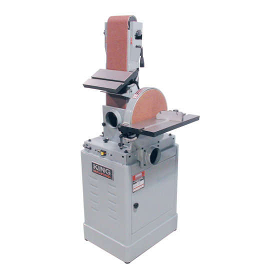
- Page 1 6” X 48” BELT & 12” DISC SANDER MODEL: KC-788FX INSTRUCTION MANUAL COPYRIGHT © 2001 ALL RIGHTS RESERVED BY KING CANADA TOOLS INC.
- Page 2 IMPORTANT INFORMATION 2-YEAR KING CANADA TOOLS LIMITED WARRANTY OFFERS A 2-YEAR LIMITED WARRANTY FOR THIS BELT & DISC SANDER FOR INDUSTRIAL USE. PROOF OF PURCHASE Please keep your dated proof of purchase for warranty and servicing purposes. REPLACEMENT PARTS Replacement parts for this tool are available at our authorized KING CANADA service centers across Canada. For servicing, contact or return to the retailer where you purchased your product along with your proof of purchase.
-
Page 3: General Safety Instructions For Power Tools
Non- slip footwear is recommended. Wear protective hair covering to contain long hair. Roll up long sleeves above the elbows. MACHINE SPECIFICATIONS Model: KC-788FX Belt size: 6” x 48” Belt table size: 5 7/8”... -
Page 4: Electrical Connections
ELECTRICAL CONNECTIONS WARNING ALL ELECTRICAL CONNECTIONS MUST BE DONE BY A QUALIFIED ELECTRICIAN. FAILURE TO COMPLY MAY RESULT IN SERIOUS INJURY! ALL ADJUSTMENTS OR REPAIRS MUST BE DONE WITH THE SANDER DISCONNECTED FROM THE POWER SOURCE. FAILURE TO COMPLY MAY RESULT IN SERIOUS INJURY! Power source 2. - Page 5 UNPACKING & GETTING TO KNOW YOUR SANDER Unpacking & checking contents To get the maximum performance out of your sander, clean it well before using and assemble it with precision. As soon as you receive your sander, we recommend you do the following; 1.
- Page 6 ASSEMBLY ASSEMBLING RUBBER FEET TO CABINET STAND Place the cabinet stand on its side with the cabinet door on top. One rubber foot must be assembled to each corner hole of the cabinet. 1. Insert a rubber foot into one of the four hole on the bottom of the cabinet stand.
- Page 7 ASSEMBLY INSTALLING BELT TABLE 1. To allow the trunnion to slide, place the belt table on the belt housing. 2. The belt table must be positioned at the 0˚ mark, this will align the trunnion with the angle indicator. 3. Use a flat washer and a lock handle to fix the belt table into position (Fig.8).
- Page 8 ADJUSTMENTS ADJUSTING BELT HOUSING POSITION The belt housing can be positioned horizontally or vertically. It can also be positioned at any angle in between depending on your sanding needs. To adjust, follow these instructions; 1. Loosen and remove the three knobs (A-Fig.12). 2.
- Page 9 ADJUSTMENTS REPLACING SANDING DISC 1. Loosen and remove the four cap screws (A-Fig.16) from the disc cover (B). 2. Loosen and remove the two top cap screws (C) from the disc dust chute. 3. Remove the disc cover (B). 4. Remove the used sanding disc from the aluminum disc. It is not necessary to remove the aluminum disc.
- Page 10 OPERATIONS & MAINTENANCE OPERATIONS MAINTENANCE • The sander must be unplugged from the power source before REGULAR MAINTENANCE adjusting or replacing parts. 1. Your work space and your sander should be clean after ever use. • The table lock handles must be properly tightened. 2.
-
Page 11: Troubleshooting
TROUBLESHOOTING Problem Probable cause Solution • Voltage drop. • Check power source. • Motor short circuit or bad connec- • Check all motor connections. • Motor doesn’t start. tion. • Press thermal overload button to • Thermal overload is tripped. reactivate.
Need help?
Do you have a question about the KC-788FX and is the answer not in the manual?
Questions and answers