Subscribe to Our Youtube Channel
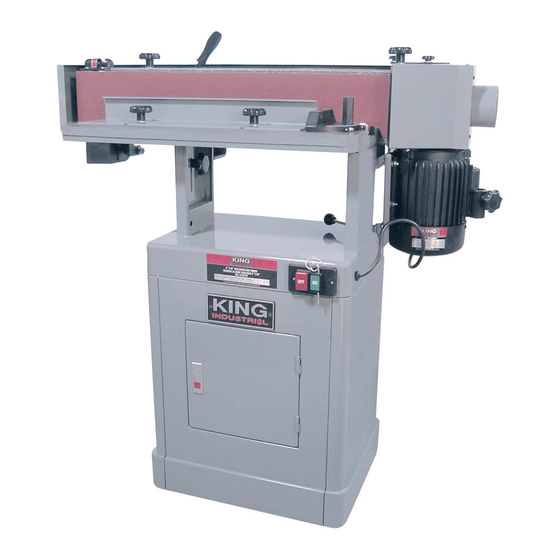
Summary of Contents for King Industrial KC-689-OSC
- Page 1 6” x 89” OSCILLATING EDGE SANDER MODEL: KC-689-OSC & KC-689-OSC-7 INSTRUCTION MANUAL COPYRIGHT © 2005 ALL RIGHTS RESERVED BY KING CANADA TOOLS INC.
- Page 2 IMPORTANT INFORMATION 2-YEAR KING CANADA TOOLS LIMITED WARRANTY OFFERS A 2-YEAR LIMITED WARANTY FOR INDUSTRIAL USE. FOR THIS OSCILLATING EDGE SANDER PROOF OF PURCHASE Please keep your dated proof of purchase for warranty and servicing purposes. REPLACEMENT PARTS Replacement parts for this tool are available at our authorized KING CANADA service centers across Canada. For servicing, contact or return to the retailer where you purchased your product along with your proof of purchase.
-
Page 3: General Safety Instructions
GENERAL SAFETY INSTRUCTIONS VOLTAGE WARNING: Before connecting the tool to a power source (receptacle, outlet, etc.) be sure the voltage supplied is the same as that specified on the nameplate of the tool. A power source with voltage greater than that for the specified tool can result in SERIOUS INJURY to the user - as well as damage to the tool. -
Page 4: Electrical Connections
ELECTRICAL CONNECTIONS WARNING ALL ELECTRICAL CONNECTIONS MUST BE DONE BY A QUALIFIED ELECTRICIAN. FAILURE TO COMPLY MAY RESULT IN SERIOUS INJURY! ALL ADJUSTMENTS OR REPAIRS MUST BE DONE WITH THE EDGE SANDER DISCONNECTED FROM THE POWER SOURCE. FAILURE TO COMPLY MAY RESULT IN SERIOUS INJURY! POWER SUPPLY outlet having the same configuration as illustrated by the grounded outlet box in Fig.2. - Page 5 GETTING TO KNOW YOUR EDGE SANDER FIGURE 4 Getting to know your Edge Sander A-On/Off Switch. Turns the machine on or off. additional support and for safety purposes. When the fence is used B-Belt Frame Lock Knob. Allows the operator to position the belt in vertical sanding operations, it allows for setting thickness or frame in a horizontal or vertical position.
- Page 6 ASSEMBLY, ADJUSTMENTS & OPERATIONS Assembly Mounting Tension Handle on Tension Lever 1) Place tension handle (A-Fig.5) over the tension lever (B-Fig.5). Mounting Workstop to Belt Frame 1) Mount the workstop (C-Fig.5) to the right side of the belt frame using the lock knob (D-Fig.5).
- Page 7 ADJUSTMENTS & OPERATIONS Changing the Sanding Belt 1) Disconnect the machine from the power source. 2) Lock the belt frame in a vertical position, see Fig.9. 3) Release the sanding belt tension by pulling the sanding belt tension lever (A- Fig.9) to the left.
- Page 8 ADJUSTMENTS & OPERATIONS Adjusting Table Height WARNING! Do not position table below sanding belt! Keep an overlap of at least 1/16” between table and sanding belt to avoid material and/or fingers getting caught! Failure to comply may cause serious injury! 1) Loosen two lock knobs (A-Fig.12).


Need help?
Do you have a question about the KC-689-OSC and is the answer not in the manual?
Questions and answers