Table of Contents
Advertisement
Quick Links
Advertisement
Table of Contents

Related Manuals for Televes T.0X COFDM-QAM CI


Summary of Contents for Televes T.0X COFDM-QAM CI
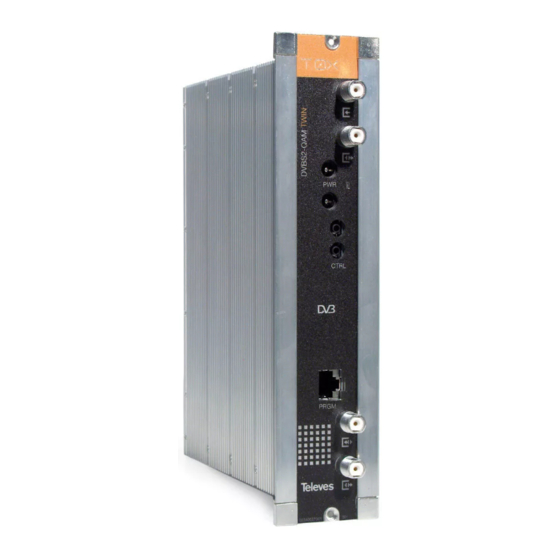
- Page 1 Ref. 563601 User instructions COFDM - QAM CI w w w . t e l e v e s . c o m...
-
Page 3: Table Of Contents
COFDM-QAM CI Contents Technical specifi cations ........................References’ descriptions ........................Mounting ............................. 3.1. Wall mounting ..........................3.2. 19” rack mounting ........................Elements’ descriptions ........................4.1. Introduction ..........................4.2. Power supply unit ........................4.3. Amplifi cation options ......................4.4. Universal programmer ......................How to use the product ........................ -
Page 5: Technical Specifi Cations
1. Technical specifi cations 1.1. COFDM-QAM CI ref. 563601 Input frequency (selec.) 177,5 - 226,5 / 474 - 858 Input return losses (typ.) >10 Frequency steps (selec.) 125, 166 Bandwidth 7; 8 COFDM input Input level -60 to -20 Input through losses (typ.) <... - Page 6 COFDM - QAM CI 1.2. Broaband Amplifi ers technical specifi cations Frequency range 46 ... 862 Connector type “F” Gain 44 ± 2,5 Powering voltage Amplifi er Regulation margin Consumption at 24 Vdc 5575 Output level (60 dB) dBμV Test socket 42 CH CENELEC Frequency range 47 ...
-
Page 7: References' Descriptions
2. Description of references Product Range Accessories 563601 COFDM-QAM CI T-0X 7234 Universal Programmer 5575 T.0X Broadband Amplifi er 44dB 120dBμV 5071 T03-T05-T.0X Wall mounting rail L=50 cm 451202 Amplifi er DTKom (47 - 862 MHz) 5239 T03-T05-T.0X Wall mounting rail (12 Modules+PSU) L=56 cm 5559 T.0X Headend Manager CDC-IP 5301... -
Page 8: Mounting
COFDM - QAM CI 3. Mounting 3.1. Wall mounting COFDM 563601 5629 5575 input CLAC! 5071 5239 UPSU120 output 4061 7234 NOTE: The use of both PSU power outputs is recommended to balance the consumption. For example, 4+3 or 3+4... -
Page 9: 19" Rack Mounting
3.2. 19” rack mounting 5301 UPSU120... -
Page 10: Elements' Descriptions
COFDM - QAM CI 4. Elements’ descriptions 4.1. Introduction CTRL PRGM 1. COFDM input 6. Status LED Insert the smartcard completely 2. QAM output 7. Control BUS connectors into the CAM slot before powering 3. RF input 8. CAM slot modules. -
Page 11: Power Supply Unit
4.2. Power supply unit Connectors to power the modules (1) On LED 24V: OK 0V: Overload or short circuit UPSU120 Mains input 230V~ NOTES: - The PSU can power a maximum of seven COFDM-QAM CI modules. - Whenever the demand of power exceeds 4A (max. current for each output), it is necessary to distribute it between the two powering outputs of the PSU. -
Page 12: Amplifi Cation Options
COFDM - QAM CI 4.3. Amplifi cation options OPTION “A” - Amplifi er ref. 5575 OPTION “B” - Amplifi er ref. 451202 TEST (-30dB) +10 dB OK - MATV 20 dB 20 dB 10 dB 10 dB 20 dB MATV OK - Return USO EXCLUSIVO EN INTERIOR C. -
Page 13: Universal Programmer
4.4. Universal Programmer PCT 5.0 The programmer features 4 buttons: (short press) - Selection of parameter (positioning of the cursor). P C T 4 . 0 Modifi cation of the parameter chosen by U N I V E R S A L the cursor (fl ashing) (short press) - Change menu (long press) - Change between Standard... -
Page 14: How To Use The Product
COFDM - QAM CI 5. - How to use the product 5.1. Standard Menu input connector (line power set to ON) the frontal LED will be blinking until it is fi xed. Insert the programmer in the front connector of the module (“PRGM”). - Page 15 Remark: The bandwidth needed will depend on • OFF No output is generated. It is indicated the service order number as well • NULL QAM output modulation with null as the total number of services in the multiplex the number of services present in the (the fi gure indicates that the 2nd service out of output (those selected as ON or DCY, packets only.
- Page 16 COFDM - QAM CI Additionally, on the upper right corner of the f. Measurements menu 2 g. Measurements menu 3 window it is indicated the status of the service This menu shows the occupancy rate of (scrambled or plain) at the input and at the The following menu indicates the unit’s current the output of the module as well as the oputput:...
-
Page 17: Extended Menu
5.2. Extended Menu • OIRT channels c. Identifi ers menu • Irland • South Africa When the key is held down for more than 3 Some DVB-C receivers may have problems • Polond seconds the unit displays a series of menus that are receiving transmodulated channels that share the •... -
Page 18: Saving Of Parameters
COFDM - QAM CI d. Versions menu To change the LCN, make use of keys or . 5.3. Saving Parameters This menu is not displayed in Transparent mode. This menu displays the fi rmware versions for Once the desired value has been selected in any the unit as well as the one of the QAM modulaor of the menus (normal or extended), in order to (FPGA). -
Page 19: Controlling The Device
6. - Controlling the Device Menu Structure This version of the COFDM-QAM CI allows confi guration and monitoring via a PC, both locally and remotely. a. Local control The “Headend Management” programme (v2.14 Long press or higher) is required, as well as a special cable (provided with the programme) that connects a PC serial port to the COFDM-QAM CI “PRGM”... -
Page 20: Example Of Application
COFDM - QAM CI 7. Example of application Distribution of 7 channels of COFDM-QAM CI 75 ohm 4061 451202 5629 7 x 563601 QAM output The diagram shows the assembly for distributing 7 QAM channels (modulesCOFDM-QAM CI). The whole current consumption of the 7 modules is distributed between the two outputs of the PSU. -
Page 21: Rackmount Standards
8. Rackmount Standards (max. 49 COFDM-QAM CI - 7 subracks with 5U height - 8,7”) These ventilators will be installed on a tray that is 8.1. Installation of the rack with fi xed on top of the cabinet (fi g. 1 & 2). This way, the ventilation facilities fans are forcing circulate the cool air that enters through the base of the cabinet between the... - Page 22 COFDM - QAM CI It is very important that this process operates 8.2. Installation of the rack without correctly, therefore the following must be ventilation facilities observed: - Do not open the side doors, as this would cause To install the units in racks without installation the ventilators to extract the air from the outside facilities, and when the rack is located in places rather than the air inside the rack.
-
Page 23: Standards For Mounting Cabinets
9. Standards for mounting cabinets IMPORTANT EXTRACTOR for forced ventilation. The scheme of recommended Must be located higher ventilation is the one shown in the than the top module. fi gure, for any way of placement of the cabinet (horizontal or vertical). Maximum environment temperature: 45ºC. - Page 24 COFDM - QAM CI IMPORTANT Horizontal placement of cabinets is strongly recommended by fi xing them as HORIZONTAL near as possible to the fl oor . If the horizontal placement is impossible, 0,2 m 0,2 m then vertical placement is allowed. Respect the recommended minimum distances in the attached schemes.
-
Page 25: Channels Table
A. Table of channels Tabl. 1 Tabl. 2 Tabl. 3 Tabl. 4 Tabl. 5 Tabl. 6 Tabl. 7 Tabl. 8 Tabl. 9 Tabl. 10 CCIR China/Taiwan Chile Italia Francia Canales OIR Irlanda Sur-Africa Polonia (OIR) Australia 50,50 52,50 57,00 56,00 45,00 52,50 48,50... - Page 26 COFDM - QAM CI 314,00 658,00 611,00 346,00 346,00 354,00 674,00 658,00 394,00 296,50 322,00 666,00 617,00 354,00 354,00 362,00 682,00 666,00 402,00 305,50 330,00 674,00 623,00 362,00 362,00 370,00 690,00 674,00 410,00 312,50 338,00 682,00 629,00 370,00 370,00 378,00 698,00 682,00 418,00...
- Page 27 642,00 857,00 674,00 674,00 682,00 722,00 585,50 650,00 863,00 682,00 682,00 690,00 730,00 592,50 658,00 690,00 690,00 698,00 738,00 599,50 666,00 698,00 698,00 706,00 746,00 606,50 674,00 706,00 706,00 714,00 754,00 613,50 682,00 714,00 714,00 722,00 762,00 620,50 690,00 722,00 722,00 730,00 770,00...
- Page 28 COFDM - QAM CI...
- Page 29 Guarantee Televés S.A. offers a two year guarantee, beginning from the date of purchase for countries in the EU. For countries that are not part of the EU, the legal guarantee that is in force at the time of purchase is applied. Keep the purchase invoice to determine this date. During the guarantee period, Televés S.A.
- Page 30 COFDM - QAM CI...
Need help?
Do you have a question about the T.0X COFDM-QAM CI and is the answer not in the manual?
Questions and answers