Table of Contents
Advertisement
Available languages
Available languages
Quick Links
π
H-9179, H-9180
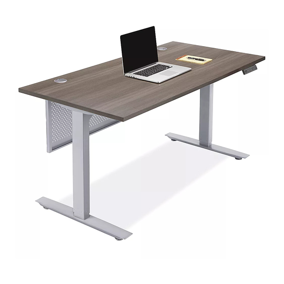
DOWNTOWN
ADJUSTABLE
HEIGHT DESK
TOOLS NEEDED
Drill
4 mm Hex Wrench
(Included)
Two Person Assembly
(Recommended)
Desktop x 1
Top Support
Control Box x 1
Bracket x 2
M6 x 33 mm
Power Cord x 1
Machine Screw x 5
MODESTY PANEL HARDWARE
Metal Modesty Panel x 1
PAGE 1 OF 18
1-800-295-5510
uline.com
5 mm Hex Wrench
(Included)
PARTS
Adjustable Frame
with Lifting Columns x 1
Programmable
Handset x 1
M6 x 15 mm Machine
Screw with Lock
Washer and Flat
Washer x 18
Modesty Panel
M6 x 12 mm
Bracket x 2
Machine Screw x 5
#
1
2
Foot with Leveling
3
Glides x 2
4
5
6
7
8
9
Cable
10
Management
Tray x 2
11
12
13
14
5 mm x 20 mm
Wood Screw x 11
5 mm x 20 mm
Wood Screw x 5
Para Español, vea páginas 7-12.
Pour le français, consulter les pages 13-18.
DESCRIPTION
Desktop
Adjustable Frame with
Lifting Columns
Foot with Leveling Glides
Top Support Bracket
Control Box
Programmable Handset
Cable Management Tray
Power Cord
M6 x 33 mm Machine Screw
M6 x 15 mm Machine Screw with
Lock Washer and Flat Washer
5 x 20 mm Wood Screw
M6 x 12 mm Machine Screw
Metal Modesty Panel
Modesty Panel Bracket
QTY.
1
1
2
2
1
1
2
1
5
18
16
5
1
2
0421 IH-9179
Advertisement
Table of Contents

Related Manuals for U-Line H-9179


Summary of Contents for U-Line H-9179
- Page 1 Para Español, vea páginas 7-12. Pour le français, consulter les pages 13-18. π H-9179, H-9180 1-800-295-5510 uline.com DOWNTOWN ADJUSTABLE HEIGHT DESK TOOLS NEEDED Drill 4 mm Hex Wrench 5 mm Hex Wrench (Included) (Included) Two Person Assembly (Recommended) PARTS DESCRIPTION QTY.
- Page 2 ASSEMBLY NOTE: Count and inspect all pieces before 4. Insert two M6 x 33 mm machine screws (9) into holes on disposing of any carton or packing materials. end of adjustable frame to connect adjustable frame with lifting columns and top support bracket. Lightly CAUTION! Adjustable frame is heavy and tighten using 5 mm hex wrench.
- Page 3 ASSEMBLY CONTINUED 6. Place desktop (1) upside down on a smooth, 8. Attach top support brackets and adjustable frame non-marring surface to prevent scratching. to desktop using drill and eight 5 x 20 mm wood Grommets should be facing down. screws (11).
- Page 4 ASSEMBLY CONTINUED 10. Connect the power for the control box (5) using 12. Align holes on modesty panel brackets (14) with holes the power cord (8). Connect the programmable on outer edge of metal modesty panel (13). Attach handset (6) and lifting column cables into the using two M6 x 15 mm machine screws (12) per bracket.
-
Page 5: Operation
OPERATION CONTROLS 24.5 Down Setting Display Four Preset USB Charger Button Button Button Position Buttons NOTE: The desk must be initialized prior to • The handset will display first use. each preset when complete. • To initialize, press and hold the down button on the •... -
Page 6: Troubleshooting
OPERATION CONTINUED • Press the up or down buttons to switch sensitivity • Press and hold the first and second preset position levels. Levels range from 1 to 8 where the higher buttons simultaneously for seven seconds until levels result in higher sensitivity. The default level is 5. is displayed. -
Page 7: Herramientas Necesarias
π H-9179, H-9180 800-295-5510 uline.mx ESCRITORIO DE ALTURA AJUSTABLE – URBANO HERRAMIENTAS NECESARIAS Taladro 1 Llave Hexagonal 1 Llave Hexagonal de 4 mm (Incluida) de 5 mm (Incluida) Armar Entre Dos Personas (Recomendado) PARTES DESCRIPCIÓN CANT. Cubierta de Escritorio Armazón Ajustable con Columnas de Elevación... - Page 8 ENSAMBLE NOTA: Cuente e inspeccione todas las piezas 4. Inserte dos tornillos para máquina M6 x 33 mm (9) en antes de desechar cualquier caja o material los orificios del extremo del armazón para conectar el armazón ajustable con las columnas de elevación de empaque.
- Page 9 CONTINUACIÓN DEL ENSAMBLE 6. Coloque la cubierta (1) boca abajo sobre una 8. Una los dos brazos de soporte superior y el armazón superficie lisa, que no deje marcas, para evitar ajustable a la cubierta usando el taladro y ocho rayones.
- Page 10 CONTINUACIÓN DEL ENSAMBLE 10. Conecte la caja de control a la electricidad (5) 12. Alinee los orificios en los soportes para panel de privacidad (14) con los orificios en el borde exterior del utilizando el cable eléctrico (8). Conecte el control panel de metal para privacidad (13).
- Page 11 FUNCIONAMIENTO CONTROLES 24.5 Botón Botón Botón de Pantalla Cuatro Botones de Cargador USB Arriba Abajo Ajuste Posiciones Preprogramadas NOTA: El escritorio debe ajustarse antes de su • El control manual indicará primer uso. cuando se complete cada programación. • Para iniciar, mantenga presionado el Botón Abajo •...
- Page 12 CONTINUACIÓN DE FUNCIONAMIENTO • Presione los botones arriba o abajo para cambiar • Presione y sostenga el primer y el segundo botón de los niveles de sensibilidad. Los niveles varían de posición preprogramada simultáneamente por siete 1 a 8, donde los niveles más altos tienen mayor segundos hasta que aparezca .
-
Page 13: Outils Requis
π H-9179, H-9180 1-800-295-5510 uline.ca DOWNTOWN – BUREAU À HAUTEUR RÉGLABLE OUTILS REQUIS Perceuse Clé hexagonale Clé hexagonale de 4 mm (inclus) de 5 mm (inclus) Montage à deux personnes (recommandé) PIÈCES DESCRIPTION QTÉ Surface de bureau Cadre réglable avec colonnes de levage Cadre réglable avec... -
Page 14: Montage
MONTAGE REMARQUE : Comptez et vérifiez toutes les 4. Insérez deux vis à métaux M6 x 33 mm (9) dans les pièces avant de jeter le matériel d'emballage trous à l'extrémité du cadre réglable avec colonnes de levage pour y fixer la ferrure de support de la surface. ou le carton. - Page 15 MONTAGE SUITE 6. Placez la surface de bureau (1) à l'envers sur une 8. Fixez les ferrures de support de la surface et le surface lisse non marquante pour éviter les rayures. cadre réglable à la surface de bureau avec la Les passe-fils doivent être orientés vers le bas.
- Page 16 MONTAGE SUITE 10. Branchez le boîtier de commande (5) à l'aide du 12. Alignez les trous des supports du panneau cache- jambes (14) sur les trous situés sur le bord extérieur du cordon d'alimentation (8). Branchez la commande programmable (6) et les câbles des colonnes de panneau cache-jambes en métal (13).
- Page 17 FONCTIONNEMENT COMMANDES 24.5 Touche Touche Bouton de Affichage Quatre touches de Chargeur USB haut réglage position préréglée REMARQUE : Le bureau doit être initialisé avant la • La commande affiche pour première utilisation. chaque préréglage une fois l'opération complétée. • Pour initialiser, appuyez et maintenez la touche •...
-
Page 18: Dépannage
FONCTIONNEMENT SUITE BLOCAGE DU FONCTIONNEMENT DU BUREAU • Appuyez sur les touches haut et bas pour alterner les niveaux de sensibilité. Les niveaux vont de 1 à 8 en REMARQUE : Le bureau est doté d'une fonction prenant en compte que les niveaux plus élevés produisent de blocage empêchant le fonctionnement.
Need help?
Do you have a question about the H-9179 and is the answer not in the manual?
Questions and answers