Table of Contents
Advertisement
Quick Links
Advertisement
Table of Contents

Related Manuals for NIVELCO NIVOCAP C-200


Summary of Contents for NIVELCO NIVOCAP C-200
- Page 1 BKI16ATEX0010X cbr2052a0600p_05 1/36...
-
Page 2: Table Of Contents
C O N T E N T S 6. PARAMETERS – DEFINITIONS AND PROGRAMMING ......24 1. INTRODUCTION ..................4 6.1. M ............24 EASUREMENT CONFIGURATION 2. ORDER CODE ( !) ........5 NOT ALL COMBINATIONS POSSIBLE 6.2. C ................27 URRENT OUTPUT 2.1. - Page 3 CAPACITANCE LEVEL MEASUREMENT 3/36 BKI16ATEX0010X cbr2052a0600p_05...
-
Page 4: Introduction
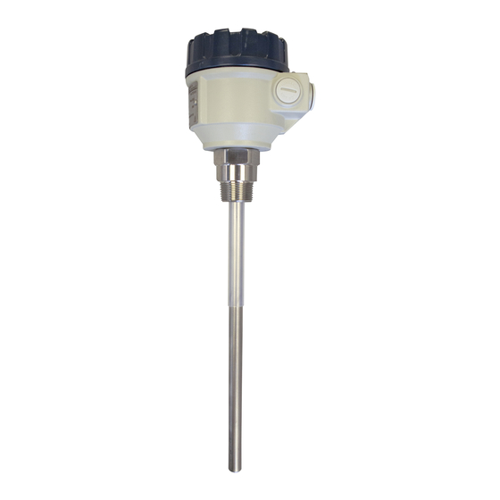
Thank you for choosing a NIVELCO instrument We are sure that you will be satisfied throughout its use 1. INTRODUCTION NIVOCAP CT–200 is a 2-wire capacitance level transmitter for measuring level and volume (weight) of conductive or not-conductive liquids or free flowing solids. -
Page 5: Order Code ( Not All Combinations Possible !)
2. ORDER CODE ( NOT ALL COMBINATIONS POSSIBLE N I V O C A P C – – ROBE LENGTH ROBE TYPE OUSING UTPUT ROCESS CONNECTION ATERIAL OD PROBE Transmitter Rod – insulated / 1" NPT Aluminum 4…20 mA Rod – insulated / 1½" NPT Plastic 0.1 m 4…20 mA + HART... -
Page 6: Accessories
2.1. A CCESSORIES HART modem SAT–304 Display module SAP–202 Weight for cable probe CTK–103–0M–40001 Reference (tube) probe NIVOCAP – 1 – 0 ERSION HREAD PROBE NSERTION LENGTH Coaxial tube / BSP Tube 1½" Coaxial tube / NPT Rod 1"... -
Page 7: Technical Data
3. TECHNICAL DATA Type Rod probe Cable probe Measurement range 0.2…3 m (0.65…10 feet) 1…20 m (3.3…65.5 feet) Threaded process connection 1.4571 stainless steel Material of wetted parts Probe Fully or partially PFA coated 1.4301 stainless steel rod Fully or partially FEP coated stainless steel cable Housing material Paint coated aluminum (EN AC-42000) or plastic (PBT) Normal type: −30…+130 °C (−22…+266 °F), high-temperature type: −30…+200 °C (−22…+392 °F),... -
Page 8: Special Data Fore X Certified Models
Temperature diagram Pressure diagram Standard probe High-temperature probe 3.1. S PECIAL DATA FOR X CERTIFIED MODELS Ex marking II 1 G Ex ia IIB T6…T3 Ga Intrinsically safe data ≤ 15 nF, L ≤ 200 H, U ≤ 30 V, I ≤... -
Page 9: Dimensions
3.4. D IMENSIONS Rod probe Cable probe High-temperature rod probe CT–2, 3– CT–2, 3– CH–2– CB–2, 3– CB–2, 3– CP–2– BKI16ATEX0010X cbr2052a0600p_05 9/36... -
Page 10: Accessories
(Returned Equipment Handling Form) must be enclosed after downloaded from our homepage www.nivelco.com. You should dispatch the device with a declaration of decontamination. In the declaration, you have to provide a statement that the decontamination process is completed, and the device is clean and free from harmful material and there is no hazardous substance on it. -
Page 11: Installation
4. INSTALLATION 4.1. M OUNTING AND WIRING The probe has to be installed vertically and for non-conductive materials reference probe should be used. The NIVOCAP probes are mounted by 1" or 1½" process connections using S = 41 or S = 55 open end wrench, respectively. It is recommended to fix the bottom end of the cable probes. -
Page 12: Checking Of The Loop Current
EMPERATURE Electronics of the unit should be protected with shelter against development of too high-temperature by direct sunshine. IRING Power must be switched off before wiring the unit. This instrument use electronic components that may be damaged by static electricity thus apply precautions commonly used e.g., touching a properly grounded point before removing cover of the enclosure ... -
Page 13: Programming
5. PROGRAMMING Since NIVOCAP is not measuring level directly, the basic element of the programming is measurement (learning) at two different levels during which the instrument is learning conditions of the actual application (shape of the tank, medium to be measured, etc.). To reach accuracy given in the table of the Technical Data these two levels should be possibly near to both end of the (rod or cable) probes (See Operation and Programming of NIVOCAP on page 4) Learning will be represented (with Programming Without Display Module 5.1 and with QUICKSET) by the adjustment of 4 and 20 mA better to say assignment of 0% and 100% to these two output values respectively. -
Page 14: Programming Without Display Module
5.1. P ROGRAMMING WITHOUT DISPLAY MODULE ROGRAMMING FEATURES 4 mA output current (direct) assignment to the minimum (0%) level 20 mA output current (direct) assignment to the maximum (100%) level 4 mA output current (indirect) assignment to the minimum (0%) level by means of an intermediate level ... - Page 15 Indirect assignment of the minimum and maximum level to the output current with partially filled tank For this programming the output current is to be measured on the test points as described in 4.2. Should higher accuracy be needed the current meter should be inserted in the 4…20 mA loop.
- Page 16 Selecting “Fault indication” by the current output As a result of the programming current output will be 3,8 mA; 22 mA. Programming steps LED State After Programming steps NIVOCAP in programming mode 1) Press key and keep it pressed 2) Press additionally key , or –...
-
Page 17: Programming With The Sap-202 Display Module
5.2. P SAP–202 ROGRAMMING WITH THE DISPLAY MODULE The NIVOCAP should be adjusted to the process by programming the parameters. The SAP–200 Display Module can be used to display the parameters while programming and measurement values during measurement. The SAP–200 supports two separately accessible programming modes as below. QUICKSET (See 5.2.5) This feature is for quick programming of the 4 basic parameters like with programming without display module but aided by images on the display. -
Page 18: Sap-202 Display Module
5.2.2 SAP–202 DISPLAY MODULE Symbols used on the LCD Symbols used on the frame LEV – Level measurement mode M – Metric (European) system VOL – Volume measurement mode US – US (Anglo-Saxon) system PROG - Programming mode ... - Page 19 Double key pressing Press the two keys simultaneously for desired programming step Entering/quitting programming mode Basic steps while parameter address is blinking Basic steps while parameter value is blinking Notes: If the parameter value is not accessible i.e., the parameter address keeps blinking after pressing ENTER ...
-
Page 20: Indications Of The Sap-202 Programming Module And The Leds
5.2.4 I SAP–202 P NDICATIONS OF THE ROGRAMMING ODULE AND THE LED indication VALID-LED – lit, in case the measured value is stabilized – blinking, in case the measured value is changing COM-LED – blinking when HART message is transmitted SAP–202 indications The following process values can be displayed or received... -
Page 21: Quickset
5.2.5 QUICKSET Suggested for simple applications Quick programming of the 4 basic parameters (like with programming without display module but) aided by images on the display. Measured values can only be displayed in percentage. QUICKSET can only be used in (%)(DEFAULT) mode (See P01 in Full Parameter Programming 5.2.6). Keys Function Enter/Quit QUICKSET programming mode... - Page 22 Screen Actions Assignment of 20 mA to the maximum level, % Fill the tank to the level required. After entering the Quickset programming mode, the learning function can be started with the double key pressing . During learning the image „Store” is displayed. The parameter value represents degree in %.
-
Page 23: Full Parameter Programming
5.2.6 F ULL PARAMETER PROGRAMMING Full Parameter Access is the highest programming level to access all features provided by the NIVOCAP, level, volume and weight can also be displayed in engineering units. Description of the parameters can be found under 6. paragraph. Keys Function Enter/quit Full Parameter Programming mode. -
Page 24: Parameters - Definitions And Programming
6. PARAMETERS – DEFINITIONS AND PROGRAMMING 6.1. M EASUREMENT CONFIGURATION P00: - c b a Engineering Unit System Factory default will be reloaded in the corresponding engineering units by programming this parameter. Therefore, all parameters have to be set again. Operating mode Always 0 Attention: mind the sequence! - Page 25 P01: - - - a Measurement mode Parameter value “a” will determine the basic measurement value that will be displayed and proportional with the current output. Depending on the value of “a” process values as listed in the 3 column can also be displayed by pressing .
- Page 26 P03: - - - a Displayed values – Rounding Volume (VOL) display Value displayed Display arrangement Decimal position will be shifted with increasing value displayed. (See table at the left). 0,000 – 9,999 x,xxx Values over one million will be displayed in exponential format whereas the 10,000 –...
-
Page 27: Current Output
If level, level percentage, volume or volume percentage should be measured (a ≠0 in P01) as well as level and volume should be read with relevant engineering units, then first data pair (e.g., 0% and corresponding minimum level in [m]and last two data pair (e.g., 100% and corresponding maximum level in [m]of the linearization table should be entered. -
Page 28: Measurement Optimalisation
6.3. M EASUREMENT OPTIMALISATION P20: - - - a Damping This parameter can be used to reduce unwanted fluctuation of the display and output. Damping (sec) Remark No damping Applicable Recommended Recommended Recommended Recommended Applicable Applicable DEFAULT: 10 sec P32: Density of the medium (kg/dm or lb/ft in accordance with setting of (c) in P00) -
Page 29: 32-Point Linearisation
P41-45: Tank dimensions Standing cylindrical tank Standing cylindrical tank Standing rectangular tank Lying cylindrical tank shape Spherical tank domed shape bottom with conical bottom a = 2, b = 1 a = 3 a = 4, b = 0 a = 0 a = 1, b = 0 Flat bottom P43, P44 and... - Page 30 P48: Linearization table Linearization table is represented by 32-point data pairs containing capacitance in the left column (indicated by “L”-on the display) and LEVEL, VOLUME or WEIGHT in the right column (indicated by “r”-on the display). Left column “L” Right column “r” Capacitance percentage LEVEL, VOLUME or WEIGHT After entering data pairs, the unit will...
-
Page 31: Service Parameters ( Read Only )
6.6. S ERVICE PARAMETERS READ ONLY P60: Overall operating hours of the unit (h) Display of the elapsed time Number of operating hours Indication form 0 to 999,9 h xxx,x 1000 to 9999 h xxxx Over 9999 h x,xx:e represents x,xx * 10 P61: Time elapsed after last switch-on (h) Indication form as under P60... -
Page 32: Simulation
6.8. S IMULATION This function enables the user to test the settings of the outputs. The NIVOCAP can simulate the static or continuous change of level according to the simulation cycle time, high level and low-level set in P85, P86 and P87. (The simulation levels must be within the programmed measuring range set in P04 and P05.) After selecting simulation type in P84 and setting simulation values Measurement Mode has to be re-entered. -
Page 33: Error Codes
7. ERROR CODES Error Overwriting LED-Blinking Error description What to do Current output code indication Memory failure Contact service Continuous 22 mA Capacitance to be measured is too high or Check adjustment and installation conditions. damaged probe insulation Check the probe. Programmed (Level over the upper limit) Repeat programming (teaching)! - Page 34 Error Overwriting Error description What to do LED-Blinking Current output code indication Hardware failure Contact service Continuous 22 mA (Analogue card failure) Check adjustment and installation conditions. Range adjustment failure Repeat programming (teaching)! Level changes 22 mA (Capacitance to be measured is outside of the range available.) during teaching may also cause this error Continuous,...
-
Page 35: Summary Of The Parameters
8. SUMMARY OF THE PARAMETERS Page Title Value Page Title Value d c b a d c b a Engineering unit system – Measurement mode – Engineering units – Rounding – – Density of the medium Lower (learning) level – Higher (learning) level –... - Page 36 – – – – – – – – – – – – – Software code – – – – – Access lock cbr2052a0600p_05 May, 2016 NIVELCO reserves the right to change technical data without notice! 36/36 BKI16ATEX0010X cbr2052a0600p_05...
Need help?
Do you have a question about the NIVOCAP C-200 and is the answer not in the manual?
Questions and answers