
Related Manuals for Gardner Denver AUTO SENTRY-ES+


Summary of Contents for Gardner Denver AUTO SENTRY-ES+
- Page 1 13-9-653 GARDNER DENVER ® Version: 02 April 23, 2002 ® AUTO SENTRY - ES+ CONTROLS OPERATING AND SERVICE MANUAL...
- Page 2 TABLE OF CONTENTS Index..............................ii List Of Illustrations ..........................iii Section 1, Auto Sentry Es+ Controller....................1 Section 2, Remote-Mounted Main Motor Starters ................29 Section 3, Remote Cooling Module Starters..................31 Section 4, Service And Field Modification ................... 33 13-9-653 Page i...
-
Page 3: Table Of Contents
INDEX Advisory Troubleshooting Guide ....22 High Pressure ..........4 Auto Sentry Es+ Control Display ......3 High Temperature........4 Auto Sentry Es+ Controller Low Sump Pressure........4 Section 1.............1 Motor Protective Devices ......4 Auto Sentry Es+ Operation ......1 Other Shutdowns .........5 Automatic Mode...........2 Power Failure ..........4 Constant Run Mode........2 Separator Differential Pressure.....4... - Page 4 LIST OF ILLUSTRATIONS Figure 1-1 – Auto Sentry Es+ Display....................1 Figure 1-2 – Flow Chart ........................5 Figure 1-3 – Wiring Diagram......................15 Figure 1-4 – Wiring Diagram......................17 Figure 1-5 – Wiring Diagram......................19 13-9-653 Page iii...
-
Page 5: Auto Sentry Es+ Controller
GENERAL DESCRIPTION The Gardner Denver rotary screw compressor is prewired with all controls, motor, and starter for the voltage and horsepower at the time of ordering. It is necessary only to connect the compressor unit to the correct power supply and to the shop air line (and to the appropriate water supply if water cooled). -
Page 6: Automatic Mode
Constant run mode operation - This mode is best used in applications where there are no long periods of unloaded operation, or for minimum response time to sudden demands. The compressor unit will start and run continuously, using its modulation controls to match delivery to demand. As demand falls below the compressor capacity, the pressure will rise to the setpoint of the control. -
Page 7: Auto Sentry Es+ Control Display
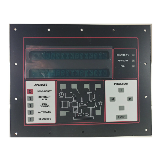
® "AUTO SENTRY -ES+" CONTROL DISPLAY The display above the keypad is used to provide operating information to the user. If a shutdown has occurred, the display will indicate the cause. During normal operation, the display will show the system (plant) pressure, compressor discharge temperature, total running hours, and operation mode. -
Page 8: Protective Shutdowns
PROTECTIVE SHUTDOWNS The controller will shut down the unit following any fault detected in the following devices. Long-term problems will have a brief blowdown period before fully shutting down. Following a shutdown, a message will be displayed, with the top line indicating "SHUTDOWN" and the lower line indicating the cause. The shutdown light will be steadily lit if the cause still exists, or will flash if the cause has been cleared. -
Page 9: Programming And Setup
Connection failure - The controller checks input connectors and will shutdown if they become unplugged. Other shutdowns - The controller runs continuous diagnostic checks of its own operation and the sensors to which it is connected. Refer to the service section for a complete listing of shutdowns and remedial actions. ®... -
Page 10: Main Adjustments Menu
Main Adjustments Menu The compressor must be stopped prior to making any adjustments. If the unit is running, press the [STOP/RESET] key to place the control in the "READY" state. Adjustments can also be performed from the "SHUTDOWN" state. After adjustments are completed, the controller returns to the this state until the cause is repaired and the controller is manually reset. -
Page 11: Maintenance Adjustments
10. This completes the operational adjustments. The controller will return to the main adjustments menu. Maintenance Adjustments If any service advisories are in effect (yellow ADVISORY indicator is on), they will be displayed on the top line. The bottom line indicates "LEAVE ADVISORY" (do not reset) or "CLEAR ADVISORY" (turn it off). Select the desired action and press [ENTER] to proceed. -
Page 12: Configuration Adjustments
In the top line, "LAG START DELAY" is displayed. The bottom line will indicate a number in the range of 1 to 600 seconds. It is factory set at 30. This is the length of time this machine will wait before starting when the pressure drops below the reset point. -
Page 13: Other Control Features
"FAN TYPE" is displayed next on the top line. Select "AIR COOLED" for units with package-mounted air coolers only. This will delay fan startup until the oil has warmed up in the package. Select "WATER COOLED" for water cooled units or any unit with a remote cooler. This will run the fan whenever the compressor motor runs. -
Page 14: Auto Restart After Power Failure
Current limiting - Current limiting is available when a controller is used on a compressor unit with TurnValve control and has current monitoring installed. This is based on the motor service factor amps programmed above. On units with TurnValves, the controller will unload as required to prevent operation above the programmed service factor amps. -
Page 15: Compressor System
Auto Sentry ES+ controlled system is the most fully-featured, functionally-complete available today. Compressor system - A proper sequencing installation requires two or more Gardner Denver rotary air compressors complete with controllers, piped into a common air system, interconnected as described above. For best performance, connect the units directly to a common header and receiver, without any intervening dryers, filters, or other restrictions. -
Page 16: Establishing The Initial Sequence
ESTABLISHING THE INITIAL SEQUENCE The first member compressor placed into sequence mode will become the lead unit. However, since any controller first placed into sequence has no way of knowing whether or not other members already exist, it will first assume the highest rotation number available. -
Page 17: Automatic Rotation
communications cable, the compressors will continue to function as two systems, one on each side of the break. Each will have its own lead unit (Seq 1) and may have lag units (depending on how many controllers are on that side of the break). -
Page 18: Connection To External Controls
CONNECTION TO EXTERNAL CONTROLS The controller offers interconnection points for external controls and indicators. This allows simple connection to remote controls and indicators, or integration into any plant-wide controls system. Remote On / Off - Remote on-off control of the system requires only a simple two-wire control, with an isolated contact suitable for 120 volts, 1 amp. -
Page 19: Figure 1-3 - Wiring Diagram
216EAP546-B (Ref. Drawing) Page 1 of 2 Figure 1-3 – WIRING DIAGRAM... - Page 20 216EAP546-B (Ref. Drawing) Page 2 of 2...
-
Page 21: Figure 1-4 - Wiring Diagram
304EBH546-C (Ref. Drawing) Page 1 of 2 Figure 1-4 – WIRING DIAGRAM... - Page 22 304EBH546-C (Ref. Drawing) Page 2 of 2...
-
Page 23: Figure 1-5 - Wiring Diagram
301EAQ546-B (Ref. Drawing) Page 1 of 2 Figure 1-5 – WIRING DIAGRAM... - Page 24 301EAQ546-B (Ref. Drawing) Page 2 of 2...
-
Page 25: Display Modes
DISPLAY MODES The normal display indicates the package service pressure, the airend discharge temperature, the total running hours, and one of the following operating modes. The green run light will be on for any operating mode, whether the compressor is running or not. READY The compressor has been stopped by pressing the [STOP/RESET] key. -
Page 26: Advisory Troubleshooting Guide
ADVISORY TROUBLESHOOTING GUIDE All advisories are indicated on the keypad by a yellow indicator in the Status area, and one of the following messages alternating with the normal lower line display. Perform service or maintenance as indicated, then clear the advisory as instructed in the operating instructions. Message Action needed CHECK COMM PORT... -
Page 27: Shutdown Troubleshooting Guide
SHUTDOWN TROUBLESHOOTING GUIDE All shutdowns are indicated on the keypad by the word "SHUTDOWN" on the top line of the display, and one of the following messages on the lower line of the display. The red indicator in the Status area will be steadily lit while the conditions exist, and will flash after the condition has been corrected. - Page 28 Message Action needed HI SYSTEM PRESS Pressure in excess of the programmed high pressure limit has been detected. The most likely cause is other, higher pressure compressors on the same air system; separate these from this compressor unit. Other possible causes are loose connections to the transducer, electrical noise and transients, or improper setting of the high pressure limit.
- Page 29 Message Action needed LV RELAY 120 volts has been removed from terminal 7 of the terminal strip. This is normally shipped jumpered directly to terminal 9, but the jumper may be removed to add a field installed shutdown switch. Reset the external switch.
- Page 30 Message Action needed POWER FAILURE The power to the compressor unit has been turned off and back on. Press [STOP/RESET] and select an operating mode. SHORTED THERM The controller has detected a shorted connection to thermistor: (A) airend discharge or (B) separator. This normally indicates a faulty connection (e.g.
-
Page 31: Controls Troubleshooting Guide
CONTROLS TROUBLESHOOTING GUIDE The following are recommended service actions. Observe all instructions noted elsewhere in this manual. All electrical service is to be performed only by a qualified electrician. Symptom Recommended action No display, Check incoming power to the compressor unit. Ensure that the Compressor stopped disconnect is on and that fuses have not blown (or circuit beaker tripped). - Page 32 Symptom Recommended action Compressor does On units with TurnValve control, the TurnValve will control delivery not modulate for moderate to heavy demands to maintain the system near the programmed set pressure, with the inlet valve held open. At light demands, the inlet valve controls the compressor delivery to maintain pressure approximately 3 psi above the programmed set pressure, with the TurnValve held open.
-
Page 33: Remote - Mounted Main Motor Starters
SECTION 2 REMOTE – MOUNTED MAIN MOTOR STARTERS CONNECTION OF REMOTE-MOUNTED MAIN MOTOR STARTERS TO ES+ CONTROL SYSTEMS The majority of our rotary screw compressor packages feature starters completely wired and tested at the factory. Some special applications and large units, however, do not have the main motor starter mounted on the package. - Page 34 With the main motor power still disconnected, press the [CONSTANT RUN] key. After a brief delay, The control should stop and display "SHUTDOWN - MAIN STARTER". This properly indicates that the starter did not function because it is turned off by the disconnect switch. Unlock and close the disconnect switch for the main motor.
-
Page 35: Remote Cooling Module Starters
SECTION 3 REMOTE COOLING MODULE STARTERS Connection of remote cooling module starters to ES+ control systems The majority of our rotary screw compressor packages feature starters completely wired and tested at the factory. Some applications and large units, however, will have the air cooled cooling module mounted remotely from the compressor package. -
Page 36: Controls Checkout
Controls checkout After installation is complete, energize both the module and the compressor package. In the controller adjustments, select "WATER COOLED" fan type. This operates the fan whenever the compressor operates, and must be used with remote-cooled units as well as water cooled units. This ensures that the oil piping does not accumulate a large quantity of hot oil before the fan starts. -
Page 37: Service And Field Modification
SECTION 4 SERVICE AND FIELD MODIFICATION CONTROLLER REPLACEMENT The controller is mounted into the starter enclosure with fourteen nuts and lockwashers. In most slope- top enclosures (40-100 HP models), these are visible when an access panel on the back of the box is removed. - Page 38 For additional information contact your local representative or Gardner Denver Compressor and Pump Division, 1800 Gardner Expressway, Quincy, Illinois 62301 Customer Service Department Telephone: (800) 682-9868 FAX: (217) 224-7814 Sales and Service in all major cities. Specifications subject to change without notice.
Need help?
Do you have a question about the AUTO SENTRY-ES+ and is the answer not in the manual?
Questions and answers