
Related Manuals for Gardner Denver Welch VCpro 600 Series


Summary of Contents for Gardner Denver Welch VCpro 600 Series
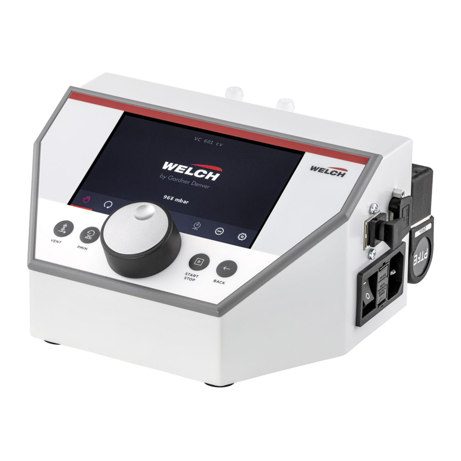
- Page 1 Operation Manual (EN) Translation of the original operation manual Welch VCpro 600 Series Vacuum Controller Device models: ► VCpro 601 Vacuum control valve ► VCpro 602 Motor speed control 600100 Revision 0 2019-10-30...
- Page 2 © 2019 Am Vogelherd 20 Reprint or duplication, also in excerpt, are not permitted without written ap- 98693 Ilmenau proval from Gardner Denver Thomas Germany GmbH. T +49 3677 604 0 F +49 3677 604 131 All rights under the copyright laws are expressly reserved by Gardner Den- welch.emea@gardnerdenver.com...
-
Page 3: Table Of Contents
Contents Contents Important Information ................5 Note for the user/personnel ....................5 Depiction of warning notices and information ..............5 Explanations of safety symbols.................... 6 Legend for the abbreviations ....................7 Safety ......................8 General ..........................8 Use ............................8 2.2.1 Proper use.......................... - Page 4 Contents Operating modes and system settings ................27 6.2.1 Operating mode 1 Manual ....................27 6.2.2 Operating mode 2 Automatic .................... 28 6.2.3 Operating mode 3 Program ....................29 6.2.4 Operating mode 4 Multi-pump ................... 30 6.2.5 Operating mode 5 Self-cleaning ..................30 6.2.6 System settings .........................
-
Page 5: Important Information
Important Information Important Information ATTENTION ► Read operation manual carefully before use. ► Keep operation manual for later reference. Note for the user/personnel Safety The user/personnel must have read and understood the operation manual completely be- fore starting work. ... -
Page 6: Explanations Of Safety Symbols
Important Information Explanations of safety symbols ► General warning symbol ► High voltage warning ► Explosive materials warning ► Hot surface warning ► Poisonous substances warning ► General prohibition ► General mandatory sign ► Disconnect from power ► Protective clothing – gloves ►... -
Page 7: Legend For The Abbreviations
Important Information Legend for the abbreviations Abbreviation Designation or meaning Explanation Ampere - current strength Electrical unit absolute Value specification Alternating current Electrical unit Atmosphere Pressure specification Direct current Electrical unit Nominal diameter – inner diameter Dimension specification (French: diamètre nominal) EPDM Ethylene propylene diene rubber Material... -
Page 8: Safety
Adherence to the operation manuals for connected vacuum pumps and laboratory vacu- um systems from Gardner Denver Thomas GmbH Use of approved spare parts and accessories from Gardner Denver Thomas GmbH ► Any other use will be regarded as improper! 2.2.2... -
Page 9: Foreseeable Misuse
Safety 2.2.3 Foreseeable misuse ATTENTION ► Misuse is generally FORBIDDEN. It also counts as improper! Regarded as foreseeable misuse are the following: Operation in explosive atmospheres Conveying of critical gas (outside of the specifications in section 6.5 Solvents table) ... -
Page 10: Protective Measures
Safety Specialized Manufacturer / Activity User personnel workshop Service (cleaning) Replacement of spare parts Decommissioning Decontamination * *or having this done by qualified and authorized service providers Protective measures All protective measures must be the highest priority in order to protect the life and health of personnel. -
Page 11: Explosive Gases
Safety For applications with hazardous materials, the following must be heeded: Adhere to the requirements of the manufacturer's safety data sheets for hazardous mate- rials. Prevent the escape of poisonous and environmentally-damaging substances from the apparatus. To protect the environment and the apparatus, use a separator (e.g. condenser). ... -
Page 12: Mechanics
Safety 2.5.4 Mechanics ATTENTION ► In case of improper use of manipulation of the device, there can be property damage to the connected vacuum pump or vacuum apparatus! Operate the device only according to the operation manual and the instructions in the opera- tion manuals for the connected devices! Operation with overpressure is not permitted with the device. -
Page 13: Network Safety
Safety Network safety ATTENTION ► The vacuum controller is network-capable via the LAN connection. This introduces the possibility of external access to the vacuum controller. Unauthorized access can cause manipulation of the applications. The operator must guarantee network security in order to prevent undesired access to the vacuum controller. -
Page 14: Technical Data
Technical data Technical data Properties Parameters Data Unit Device model VCpro 601 VCpro 602 Item number 600100 600101 Whole device Degree of protection IP 20 + 15 … + 30 Operating temperature °C 115 … 240 Rated voltage V AC Rated power Frequency 50 / 60... -
Page 15: Interfaces
Technical data Parameters Data Unit Pressure sensor (internal) Sensor type capacitive Measurement range 1 - 1100 mbar Precision in total linearity, hysteresis and < ± 0.3 % FS reproducibility Interfaces Pin assign- Control connections Connection type ment Serial RS 232, 9-pin D-Sub plug OUT: RJ 45, min. -
Page 16: Pneumatic Connections
Technical data Pneumatic connections Connections Connection type Connection: Inert gas (ventilation valve) Hose nozzle DN 4 Connection: Vacuum apparatus Hose nozzle DN 8 Connection: Vacuum pump Parts in contact with internal gas Components Material Valve block including hose nozzles Vacuum control valve PVDF, PTFE Ventilation valve FKM,... -
Page 17: Description
Description Description Function The VCpro 600 series vacuum controller is a measurement and control/regulation device for vacuum processes. The regulation and control is done by inputting parameters for "set- points" and the querying of the "actual values“. This allows a regulation and monitoring of the vacuum processes in various operation modes: ... -
Page 18: Operating Elements And Navigation Of The Vacuum Controller
Description Pos. Designation Vacuum apparatus – connection Vacuum pump – connection Metal housing Electromagnetic vacuum control valve (only VCpro 601 model) RS 232 PC connection RJ 45 LAN connection Power socket Device main switch I/0 Operating and display elements OPERATING ELEMENTS: see Chapter 4.3.1 Operating elements and display EXPLANATION OF THE SYMBOLS: see Chapter 4.5 Explanation of the symbols OPTIONALLY available: see Chapter 4.7 Accessories (options) ... - Page 19 Description Pos. Symbol Designation / Explanation function Toolbar Vacuum control valve Lights up if valve is open. Ventilation valve Lights up if valve is open. Device model VCpro 602: Motor The relative motor speed is displayed in percent on the motor symbol. Cooling water valve Lights up if valve is open.
- Page 20 Description Pos. Symbol Designation / Explanation function Primary function: Device model VCpro 601: Vacuum control valve opens. Device model VCpro 602: Maximum pressure drop at PMIN 100 % motor speed. Secondary function: Pressure input: table with solvents appears on the screen. NOTE See Chapter 6.5 Solvents table Start and stop the active operating mode...
-
Page 21: Navigation
Description 4.3.2 Navigation The user interface for the vacuum controller features three levels: Level Description Start window Parameter for the operating mode/system settings Active operating mode On the start window (level A), the operating mode of system setting is selected with a TURN of the rotary encoder. -
Page 22: Vacuum Controller Vcpro 602 (Motor Speed Control)
Description Schematic diagram – connection of the vacuum controller VCpro 601 Vacuum controller device Coolant system, return pressureless * Suction line * Water valve WV * Exhaust Level sensor FFS* Rotary evaporator * Labor vacuum system LVS * expandable * not included in scope of delivery 4.4.2 Vacuum controller VCpro 602 (motor speed control) Figure... -
Page 23: Explanation Of The Symbols
Description Schematic diagram – connection of the vacuum controller VCpro 602 Vacuum controller device Coolant system, return pressureless * Suction line * Water valve WV * Exhaust Level sensor FFS* Rotary evaporator * Labor vacuum system LVS ef (ecoflex) * Motor speed-controlled pump * not included in scope of delivery Explanation of the symbols... -
Page 24: Interfaces
Description Interfaces The following functions are possible via interfaces: Installation of the firmware on the end user device via PC software WELCH-Control 601 Installation and update as well as operation of the vacuum controller via PC software WELCH-Control 601 via the interfaces RJ 45 LAN and RS 232 ... -
Page 25: Assembly And Installation
Assembly and installation Assembly and installation Unpacking Unpack the device carefully. Check for: Transport damage, Matching with the specifications of the delivery contract and Completeness of the delivery. Inform us immediately if there are differences from the contractually agreed-upon scope of delivery or damage! Heed the manufacturer's General Terms and Conditions. -
Page 26: Communication Interfaces
Assembly and installation Communication interfaces For communication with the device via LAN (RJ45), a connection cable with at least CAT-6 must be connected. For the serial connection (RS232), a standardized cable can be used. ATTENTION ► Switch the device off before connecting or disconnecting the communication interfaces. -
Page 27: Operation
Operation Operation Start-up ATTENTION ► Read the safety instructions before start-up see Chapter 2 Safety. 1. Connect the device according to the specification and the figures; see Chapter 3.3 Pneu- matic connections and 4.4 Device models. 2. Use the device main switch I/O to switch on the vacuum controller. After a brief initializa- tion routine, during which STARTING is show, the vacuum controller is ready for opera- tion. -
Page 28: Operating Mode 2 Automatic
Operation 6.2.2 Operating mode 2 Automatic In the operating mode Automatic a material separation of a mixture up to maximum 4 com- ponents can be performed. PARAMETER VALUE UNIT Detection Gradient mbar / min ∆p Distillation Ramp mbar ∆t Distillation Ramp 00:00:00 hh:mm:ss Number of Cycles... -
Page 29: Operating Mode 3 Program
Operation 6.2.3 Operating mode 3 Program In the operating mode Program any pressure profile between 1100…0 mbar can be programmed and up to 100 cycles run. PARAMETER VALUE Unit Adjust Pressure Table Line(s) Number of Cycles Vent at Finish Parameter Values from/to Resolution Default... -
Page 30: Operating Mode 4 Multi-Pump
Operation Add and delete line Line Activity Select Add new line by encoder PRESS the encoder and the new line will be added Select the line (parameter time ∆t or pressure p) to be deleted Delete The encoder PRESS hold 2 sec and the line will be deleted Graphic example for a series of pressure setpoints p and the associated setting times ∆t Time [sec]... -
Page 31: System Settings
Operation Parameter Values from/to Resolution Default Unit 1…600 Cleaning Time The ventilation valve is opened and, due to the flow rate generated by the pump, the pump and the pneumatic supply lines are purged in the specified time. The respective device mod- els are controlled as follows: VCpro 601 model ... - Page 32 Operation Parameter Values from/to Resolution Default Unit 2 – Display 0…100 Brightness Color scheme Light Light Dark Pressure unit mbar mbar Torr Pressure scale Logarithmic Logarith- Linear NOTE Logarithmic and linear output of the pressure range for both numerical and graphic display.
- Page 33 Operation Parameter Values from/to Resolution Default Unit Auto start No / Yes In case of power failure, the last active operating mode is started again. NOTE An automatic start-up can cause undesired reactions. Heed the Safety in Chapter 2.5.6 System functions! Cooling water Always Always...
- Page 34 Operation Parameter Values from/to Resolution Default Unit 7 – Network DHCP Dynamic Dynamic Static IP address 0.0.0.0 - Subnet mask 1.1.1.1 0.0.0.0 255.255.255.255 Gateway Status (info view) The vacuum controller is network-capable. Using an Ethernet connection, the controller can be connected to the LAN and controlled using PC software. Firmware updates can also be performed via LAN.
-
Page 35: Configuring The Vacuum Controller
Operation Configuring the vacuum controller 6.3.1 Access control The device offers the opportunity to grant access rights using two profiles. USER password: protects the vacuum controller's operating area. The password is also required on restart or to unlock the device. ... -
Page 36: Reset To Factory Settings
Operation Display log files 1. Select the "System settings" menu option. 2. Select the "Log files" menu option. 3. Select the "Log files" menu option. 4. Select a log file. 5. Confirm your entry. Delete log files 1. Select the "System settings" menu option. 2. -
Page 37: Connection Settings
Operation 6.4.2 Connection settings The vacuum controller can be addressed via RS232 or LAN. Using the menu bar (see Chapter 6.4.3 Main screen) it is possible to establish the connection under [Communi- cation Settings!]. 1. Use the toggle switch Port (1) to toggle between RS232 and LAN. 2. -
Page 38: Main Screen
Operation 6.4.3 Main screen When starting the PC software and by pressing the Measure (A) button, you open the main screen. The graphic shows the course of the pressure over time (C). Here, both the time and the pressure display area can be set using the parameter field (D). The keys correspond largely to the keys on the vacuum controller. -
Page 39: File
Operation Pos. Element Function <OK> Sets current pressure as setpoint, only possible with active operating mode <Down> Decrease setpoint with active operating mode by 1 mbar when pressed once continuously when pressed and held <Up> Increases temporary setpoint for active operating mode ... -
Page 40: Log Files
Operation 6.4.5 Log files On the Log Files menu, you can display and delete the data saved on the vacuum controller and on the PC. Display the log files with get list (1). Use write (2) to save the log file. Use delete (3) to de- lete the log files. - Page 41 Operation The hexadecimal formulation (the last two characters of the IO-State output) can be trans- formed into a 6-digit binary sequence, see example below. The status of the actuator or sen- sor in question is arranged from right to left in the 6-digit binary sequence. Bit status: actuator / sensor ...
-
Page 42: Settings
Operation 6.4.6 Settings Left side of the screen: Right side of the screen: System settings Settings of the values for the individual for the control system operating modes via the tabs: - Manual - Automatic - Program - MultiPump - SelfClean For detailed information, see Chapter 6.2 Operating modes and system settings. -
Page 43: Calibrate
Operation 6.4.7 Calibrate The calibration can be done here just like on the end device. A two-point calibration with comparison measurement device can be performed. Procedure 1. Evacuation of the system with search lower point (Pmin) for the lower point. 2. -
Page 44: Firmware Update
Operation CALIBRATION ► Within the vacuum controller, 2 apirs of calibration coefficients (private and public) are saved. ► The private variables correspond to the factory settings and can only be set by WELCH Quality or WELCH Service. ► The public variables can be set by the user and overrate the factory calibration. -
Page 45: Solvents Table
Operation Solvents table OPERATION MODE ► The selection of the parameter pressure via the solvent table is only possibly in the operation modes Manual and Program. 1. On the navigation bar, select the operation mode by encoder. 2. Select the parameter Set Pressure at the current operating mode. 3. -
Page 46: Maintenance And Service
Maintenance Maintenance Service TECHNICAL SERVICE ► The device must be regular serviced and inspected in case substances are used that reduce the lifetime of wetted materials. See Chapter 3.4 Parts in contact with internal gas. ► The operator is responsible for a sevice and ispection schedule to ensure safe operartion. -
Page 47: Elimination Of Operating Faults
Elimination of operating faults Elimination of operating faults Troubleshooting notes Remedy Type of error Cause with: check correct connection of the User power cable (external), fuse Device does not There is no power Check plug connector, electri- start, no display Electrician cal installation (e.g. - Page 48 Elimination of operating faults Remedy Type of error Cause with: Recalibrate pressure sensor: see Chapter 6.2.6 System set- tings 3 – Control system / Cali- bration Incorrect pressure User Calibration incorrect value specification Reset device: See Chapter 6.2.6 System set- tings 10 –...
-
Page 49: Spare Parts Overview
When placing your order, specify the name, quantity, serial number and order number! LIABILITY ► We are not liable for damage due to the installation of other parts than those provided by the manufacturer, Gardner Denver Thomas GmbH. Spare parts list device Order numbers... -
Page 50: Ordering And Service Contact
Spare parts overview Ordering and service contact Manufacturer: Gardner Denver Thomas GmbH Am Vogelherd 20 98693 Ilmenau Germany T +49 3677 604 0 F +49 3677 604 131 welch.emea@gardnerdenver.com www.gardnerdenver.com/welch Customer support +49 3677 604 0 operation manual VCpro 600... -
Page 51: Appendix
10.1 EU declaration of conformity EU declaration of conformity Translation of the original declaration (EN) Gardner Denver Thomas GmbH Am Vogelherd 20 98693 Ilmenau Germany We hereby declare under our own responsibility that the following product, based on its de- sign and construction and on the documents we have put into circulation corresponds to the EC directives and standards listed below. -
Page 52: Notes
Appendix 10.2 Notes operation manual VCpro 600... - Page 53 Appendix Gardner Denver Thomas GmbH Am Vogelherd 20 98693 Ilmenau Germany Operation manual VCpro 600...
Need help?
Do you have a question about the Welch VCpro 600 Series and is the answer not in the manual?
Questions and answers