Gardner Denver AIRSMART User Manual
Hide thumbs
Also See for AIRSMART:
- User manual (80 pages) ,
- Operating and service manual (88 pages) ,
- Operating and service manual (20 pages)

Related Manuals for Gardner Denver AIRSMART


Summary of Contents for Gardner Denver AIRSMART
- Page 1 13-17-600 Version: 04 August 18, 2014 AIRSMART CONTROLLER USER’S MANUAL (Compressor Application)
- Page 2 WARNING – PROHIBITION – MANDATORY LABEL INFORMATION Gardner Denver Rotary Screw compressors are the result of advanced engineering and skilled manufacturing. To be assured of receiving maximum service from this machine, the owner must exercise care in its operation and maintenance. This book is written to give the operator and maintenance department essential information for day-to-day operation, maintenance and adjustment.
- Page 3 Indicates a hazard with a medium level of risk, which if not avoided, COULD result in death or serious injury. Asphyxiation Hazard – Poisonous Fumes or Toxic Gas in Compressed Air Indicates a hazard with a low level of risk, which if not avoided, MAY result in a minor or moderate injury.
- Page 4 SAFETY PRECAUTIONS Safety is everybody’s business and is based on your use of good common sense. All situations or circumstances cannot always be predicted and covered by established rules. Therefore, use your past experience, watch out for safety hazards and be cautious. Some general safety precautions are given below: Failure to observe these notices could result in injury to or death of personnel.
-
Page 5: Table Of Contents
Table of Contents General Information ............................ 5 AirSmart Controller Features ......................... 5 Control Panel Features .......................... 5 Controller Operation ........................... 6 Compressor Front Panel ........................6 Control Panel Four-Line Display ......................7 Control Panel Indicator Functions ......................8 Control Panel Button Functions ......................9 Quick Start Guide ............................. -
Page 6: General Information
1 General Information The AirSmart Controller was designed specifically for use in the Gardner Denver Global Line of variable speed, rotary screw air compressors. The AirSmart Controller is also capable of controlling fixed speed air compressors which use traditional motor starters. The microprocessor-based unit can control up to three Variable Frequency motor Drives (VFDs) while monitoring all necessary temperature and pressure points within the compressor in order to safely operate the machine and satisfy user air demand. -
Page 7: Controller Operation
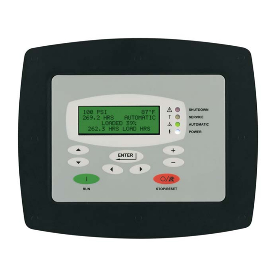
Emergency Stop Button 1. AirSmart Controller Control Panel The Control Panel is mounted on the front panel of the compressor and is used to operate the compressor and observe system status using its four-line LCD display, four status LED indicators and nine buttons. -
Page 8: Control Panel Four-Line Display
2.2 Control Panel Four-Line Display Line 1 0 PSI 75°F Line 2 125 HRS AUTOMATIC READY Line 3 NO SERVICE ADVISORY Line 4 1. Line 1 The first line of the display is used to show the package pressure and temperature while the compressor is operating. -
Page 9: Control Panel Indicator Functions
2.3 Control Panel Indicator Functions Shutdown Service 0 PSI 75°F 125 HRS AUTOMATIC READY NO SERVICE ADVISORY Automatic Power 1. Shutdown LED Indicator (red) The Shutdown LED indicates a shutdown fault in the compressor. The type of shutdown fault will be shown in the four-line display. -
Page 10: Control Panel Button Functions
2.4 Control Panel Button Functions 0 PSI 75°F 125 HRS AUTOMATIC READY NO SERVICE ADVISORY Plus Down Minus Stop/Reset Left Enter Right 1. RUN Button The RUN button is used to start the compressor. 2. STOP/RESET Button The STOP/RESET button is used to stop and blowdown the compressor. The STOP/RESET button is also used to acknowledge and reset shutdown faults or exit from the Adjustment Menu tree. - Page 11 5. Right Arrow Button The Right Arrow button is used to navigate horizontally to the next Operational or Adjustment menu. 6. Up Arrow Button The Up Arrow button is used to navigate vertically to the next item inside a menu. 7.
-
Page 12: Quick Start Guide
3 Quick Start Guide Operation of the AirSmart controller is easy. Simply select a Target Pressure and then press the Run button to start the compressor, no other settings are required. The Target Pressure comes preset to 100 PSI from the factory. The Unload Pressure is preset to 110 PSI. If a different pressure setting is desired, the following steps can be used as a guide. -
Page 13: Setting The Load And Unload Pressure
To change the Target Pressure, press the Enter button to edit the value. OPERATION ADJUSTMENT TARGET PRESSURE 100 PSI (EDIT PARAMETER) A flashing cursor will appear covering the least significant digit in the Target Pressure value, use the Plus and Minus buttons to change its value. -
Page 14: Air Compressor Control
SYSTEM PRESSURE signal on units with the optional communications module that are run in Sequence mode of operation. In a typical Gardner Denver machine, the turn valve is used to control the flow between 100% and typically 40% of full capacity while the inlet valve... -
Page 15: Fixed Speed Compressors
The AirSmart Controller can also be programmed to use only the inlet valve for flow control over the full capacity range of the machine. At full capacity, the inlet valve is fully open and the turn valve is in the fully closed state. As the air... -
Page 16: Airsmart Controller Menus
5 AirSmart Controller Menus The AirSmart Controller has two sets of menus that serve as a window into the operation of the compressor. The first set is the Operational Menus, which allow the user to observe the current status of various parts of the compressor like the motor(s) or the air-oil separator. - Page 17 13-17-600 Page 16...
- Page 18 4.1.1 Operation Menu The Operation Menu gives the user the ability to change the pressure set points and the operating mode while the compressor is running or stopped. While in the Operation menu, small incremental changes can be made to the parameter values using the Plus and Minus buttons.
- Page 19 Auto Timers. SEQUENCE: The compressor is part of a sequenced group of machines. Refer to Gardner Denver document 13-17-604 for further details about sequencing with the AirSmart Controller. LOW DEMAND: The compressor uses its internal modulation algorithms but motor(s) will NOT stop after it goes through the timed unload/blowdown sequence.
- Page 20 4.1.2 Maintenance Info Menu The Maintenance Menu gives the user access to the current status of all the maintenance counters and system timers. 0 PSI 75°F 125 HRS AUTOMATIC READY MAINTENANCE INFO 1. Total Hours The first item in the Maintenance Info menu is the total number of hours the compressor has been in operation.
- Page 21 4. Time To Next Oil Change The next item in the Maintenance Info menu is the number of hours before the next oil change is needed. The Oil Change Interval Timer can be reset under the Maintenance Adjust menu. The Oil Change Interval Time can be changed under the Unit Setup Adjust menu.
- Page 22 8. Time To Control Box Filter Change The next item in the Maintenance Info menu is the number of hours before the next control box filter change is needed. The Control Box Filter Change Interval Timer can be reset under the Maintenance Adjust menu.
- Page 23 12. Auto Timer The next item in the Maintenance Info menu is the current value of the Auto Timer. The Auto Timer is used to control the amount of time the compressor will run during the blowdown process. The Auto Timer interval is set under the Operation Adjust menu in the Adjustment Menu tree. 0 PSI 75°F 125 HRS...
- Page 24 TOTAL COST 55.39 $ 18. Firmware Version The next four items in the Maintenance Info Menu show the current versions of the AirSmart Controller Firmware, the Controller Model Table, the Controller Language Table and the Communications Module firmware (if installed) that are loaded into the AirSmart Controller.
- Page 25 19. Time and Date The last item in the Maintenance Info Menu is the current time and date kept by the battery backed, real time clock on the Communications Module. The time and date can be changed under the Time Adjust menu. This menu item is not displayed if the optional Communications Module is not installed.
- Page 26 4.1.3 Pressures and Temps Menu The Pressures and Temps menu gives the user access to the current status of all pressure and temperature values in the compressor package as well as the status of any optional sensors installed in the compressor package. 100 PSI 95°F 125 HRS...
- Page 27 4. Discharge Temperature The next item in the Pressures and Temps menu is the Discharge Temperature, which reflects the current temperature at the discharge of the airend but before the air-oil separator. The Discharge Temperature value is seen in the first line of the display if there is no Plant Temperature sensor in the system.
- Page 28 8. Separator Temperature The next item in the Pressures and Temps menu is the Separator Temperature, which reflects the current temperature at the “dry side” of the air-oil separator. 100 PSI 95°F Note: This parameter is not 125 HRS AUTOMATIC available in all compressor LOADED 100%...
- Page 29 12. Oil Pressure The next item in the Pressures and Temps menu is the Oil Pressure, which reflects the current oil pressure at the oil manifold, which is the main distribution point for the oil injection system. 100 PSI 95°F ...
- Page 30 4.1.4 Motor Information Menu The Motor Information menu gives the user access to the current status of all the Variable Frequency Drive (VFD) controlled motors (up to three) that are installed in the compressor. The Motor Information menu is not visible if no VFDs are installed with the exception of Motor Current which is visible if the current sensor option is installed in a fixed speed compressor.
- Page 31 3. Motor Power The next item(s) in the Motor Information menu is the Motor Power consumption value of each individual motor in the system followed by the total power consumption of all the motors. In the first display below, “MTR1” is followed by “MTR2” and “MTR3” depending on which motor is being observed.
- Page 32 This value indicates the speed at which each VFD has been commanded to run by the AirSmart controller. In the display below, “V1” is followed by “V2” and “V3” depending on which drive is being observed.
- Page 33 4. Drive Fault The next item(s) in the Drive Information menu is the fault value of each individual drive in the system. In the display below, “DRIVE1” is followed by “DRIVE2” and “DRIVE3” depending on which drive is being observed. 100 PSI 95°F 125 HRS...
- Page 34 8. Motor Nameplate Full Load Amps The next item(s) in the Drive Information menu is the Motor Nameplate Full Load Amps (FLA) value of each individual motor in the system. In the display below, “V1” is followed by “V2” and “V3”...
- Page 35 4.1.6 Advisory History Menu The Advisory History menu gives the user immediate access to the system status during the last six advisory faults in the compressor. 0 PSI 75°F 125 HRS AUTOMATIC READY ADVISORY HISTORY 1. Advisory #1 through #6 By using the Up and Down buttons, each of the advisories (up to six) is shown in the...
- Page 36 3. System Status List The following is the list of the status items that are stored at the time of an Advisory or Shutdown fault. Advisory/Shutdown count since last EEPROM reset Total machine hours Date and time* ...
- Page 37 These values indicate the minimum and maximum speed at which each VFD can be commanded to run by the AirSmart Controller. In the display below, “V1 CALC MN” is followed by “V1 CALC MX”, “V2 CALC MN” and “V2 CALC MX” depending on which drive is being observed and is present in the system.
- Page 38 4. Fan Control Voltage The next item in the Diagnostics menu shows the current value of the Fan Control Voltage for machines with voltage controlled variable speed cooler fans. The voltage value will increase with increasing compressor output power. 100 PSI 95°F ...
-
Page 39: Adjustment Menus
5.2 Adjustment Menus The Adjustment Menus are only available when the compressor is stopped. To enter the Adjustment Menu tree, press the Enter button and then press the Right or Left buttons to access one of four different menus. Once the desired menu heading is shown in the second line of the display, press the Enter button again to access that menu. - Page 40 13-17-600 Page 39...
- Page 41 Stop/Reset button for five seconds when the compressor is stopped. The AirSmart controller can have up to eight different language translations available at one time in the Controller Language Table, which is stored in the controller’s memory.
- Page 42 3. Unload Pressure The next item in the Operation Adjustment menu is the Unload Pressure. This pressure value is where the compressor will unload and begin the unload/stop sequence. The Unload Pressure value cannot be set any lower than [Target Pressure + 5 PSI]. If the Target Pressure setting is changed, the Unload Pressure setting will be automatically changed by the same amount as the Target Pressure setting.
- Page 43 Auto Timers. SEQUENCE: The compressor is part of a sequenced group of machines. Refer to Gardner Denver document 13-17-604 for further details about sequencing with the AirSmart Controller. LOW DEMAND: The compressor uses its internal modulation algorithms but motor(s) will NOT stop after it goes through the timed unload/blowdown sequence.
- Page 44 9. Start Timer The next item in the Operation Adjustment menu is the Start Timer. The Start Timer is used to extend how long the compressor will run in the “Pause” state before it is allowed to start modulating. OPERATION ADJUSTMENT START TIMER 0 SECONDS (SELECT PARAMETER)
- Page 45 12. Blowdown Counter The next item in the Operation Adjust menu is the Blowdown Counter, which is used to control the number of complete unload/blowdown cycles the compressor will execute. When the Blowdown Counter reaches zero, the compressor will skip the Unload State and go directly to the Blowdown State.
- Page 46 15. Auto Restart The next item in the Operation Adjustment menu is the Auto Restart function. If Auto Restart is turned on, the compressor will resume operation in the mode it was in prior to the power interruption when power is restored. OPERATION ADJUSTMENT AUTO RESTART (SELECT PARAMETER)
- Page 47 Week Clock Control is turned on, the compressor can be started and stopped using the seven programmable timers under the Time Adjust menu. This menu item is not displayed if the optional Communications Module is not installed. Consult Gardner Denver document 13-17-604 for more information about timed start/stop or secondary pressures operation.
- Page 48 4.2.2 Maintenance Adjust Menu The Maintenance Adjust menu provides a means for resetting the maintenance timers after servicing the compressor. ADJUSTMENT MENU MAINTENANCE ADJUST (SELECT SUB MENU) 1. Maintenance Timers The six timers under the Maintenance Adjust menu are: Oil Filter Change Timer Oil Change Timer Oil Sample Timer Oil Separator Element Change Timer...
- Page 49 The Sequence Adjustment menu provides access to the parameters that control the sequencing operation of the compressor. This menu is only visible if the optional AirSmart Communications Module, Gardner Denver P/N 301ETK1173, is installed. Refer to Gardner Denver document 13-17- 604 for operation of the compressor in Sequence Mode.
- Page 50 2. Oil Filter Change Interval The next item in the Unit Setup Adjust menu is the Oil Filter Change Interval. This value sets the default oil filter change countdown timer value that gets set under the Maintenance Adjust menu. Setting this parameter to zero will disable the timer and its associated alarms. UNIT SETUP ADJUST OIL FILTER CHNG INT 1000 HRS...
- Page 51 5. Separator Element Change Interval The next item in the Unit Setup Adjust menu is the Separator Element Change Interval. This value sets the default separator change countdown timer value that gets set under the Maintenance Adjust menu. Setting this parameter to zero will disable the timer and its associated alarms.
- Page 52 8. Motor Lubrication Interval The next item in the Unit Setup Adjust menu is the Motor Lubrication Interval. This value sets the default motor lubrication countdown timer value that gets set under the Maintenance Adjust menu. Setting this parameter to zero will disable the timer and its associated alarms. UNIT SETUP ADJUST MOTOR LUBE INTERVAL 8000 HRS...
- Page 53 10. Over Temperature Shutdown Limit The next item in the Unit Setup Adjust menu is the Over Temperature Shutdown Limit. This value sets the maximum internal temperature limit where the compressor will shut down UNIT SETUP ADJUST OVER TEMP LIMIT 240°F (SELECT PARAMETER) Min Value: 175F (79C)
- Page 54 12. Plant Temperature Shutdown Limit The next item in the Unit Setup Adjust menu is the Plant Temperature Shutdown Limit. This value sets the maximum package discharge temperature limit where the compressor will shut down. This menu item is not visible if there is no plant temperature sensor installed in the system.
- Page 55 15. Dryer Temperature Alarm Limit The next item in the Unit Setup Adjust menu is the Dryer Temperature Alarm Limit. This value sets the dryer temperature limit at which the compressor will give and advisory alarm. This menu item is not visible if there is no integrated dryer installed in the system. UNIT SETUP ADJUST ...
- Page 56 18. Motor Jog The next item in the Unit Setup Adjust menu is the Motor Jog function, which will cause all of the motors in the compressor package to run for the programmed amount of time as soon as the Enter button is pressed.
- Page 57 19. Drain Close/Open Intervals The next two items in the Unit Setup Adjust menu are the Water Drain Close/Open Intervals, which are used to control a solenoid operated drain valve in a water separator unit, integrated dryer unit or oil scavenge system. The Drain Close Interval is variable and dependent upon the speed of the main motor using the following formula: Actual Drain Close Time = Drain Close Interval / (% of Full Speed / 100).
- Page 58 21. Motor Heater The next item in the Unit Setup Adjust menu is the Motor Heater function. The Motor Heater provides a DC signal to warm the motor windings of the main motor(s) for starting in cold environments. UNIT SETUP ADJUST ...
- Page 59 The last item in the Unit Setup Adjust menu is the System Capacity setting. This parameter is used by the lead machine in a sequencing group to determine running speeds and other sequencing related operations. Refer to Gardner Denver document 13-17-604 for operation of the compressor in Sequence Mode.
- Page 60 The Time Adjustment menu provides access to the parameters that control the real time clock operation of the compressor. This menu is only visible if the optional AirSmart Communications Module, Gardner Denver P/N 301ETK1173, is installed. Refer to Gardner Denver document 13-17- 604 for operation of the compressor real time clock functions.
- Page 61 2. Total Run Hour Meter The next item in the Configuration Adjust menu is the Total Run Hour Meter, which records the number of hours that the compressor main motor has been running. The value of this hour meter is shown in line 2 of the normal display and in the Maintenance Info menu. This parameter can not be changed and will not appear in the menu tree unless the current value is zero.
- Page 62 4. Pressure Transducer Zero Set The next items in the Configuration Adjust menu are used for setting the zero point of the pressure transducers in the compressor. The following is a list of possible pressure transducers. Not all compressor models will have all six transducers. 1.
- Page 63 CONFIGURATION ADJUST DISTRIBUTOR INFO 1 GARDNER DENVER (SELECT PARAMETER) 6. Distributor Information #2 The next item in the Configuration Adjust is the second Distributor Information screen. This parameter is used to set up a contact number, which appears in the display when a service item such as an air filter or oil change is needed.
- Page 64 8. System Voltage The next item in the Configuration Adjust is the System Voltage, which should be set to line voltage value connected to the compressor. This parameter controls the maximum speed limits used in variable speed compressor applications. Failure to set this parameter to the correct value may limit the maximum running speed of the unit.
- Page 65 11. Temperature Transducer Offsets The next items in the Configuration Adjust menu are used for adding a fixed offset value to the temperature transducers in the compressor. The following is a list of possible temperature transducers. Not all compressor models will have all seven transducers. 1.
-
Page 66: Error Management
To that end, there are numerous tests that are performed every second by the AirSmart Controller in order to determine the state of the compressor system. Many of those tests are designed to check if certain parameters have been exceeded so that action can be taken to protect the machine. - Page 67 3. Ambient Temperature Limiter The third limiter function is the Ambient Temperature Limiter which becomes active if the ambient temperature becomes greater than 113 F (45. C) When the Ambient Temperature Limiter is active, the display will read as shown below. 100 PSI 85°F 125 HRS...
-
Page 68: Advisory Faults
6.2 Advisory Faults The advisory faults in the AirSmart Controller are designed to alert the user of needed service or that or that certain parameters may be approaching their shutdown level. Advisory faults can be reset while the compressor is running or stopped by pressing the Enter button. - Page 69 The following table is a list of advisory faults that can occur in the AirSmart Controller: Advisory Advisory Text Description Action Differential pressure > 8 Change separator #301 CHANGE SEPARATOR PSIG element Vacuum switch after inlet air #302 CHANGE AIR FILTER...
- Page 70 Advisory Advisory Text Description Action Pressure switch in oil filter #320 Change oil filter CHANGE OIL FILTER assembly has tripped Digital input programmed for #321 LOW VOLTAGE Check line voltage Low Voltage has tripped Digital input programmed for Check main motor(s) #322 MOTOR OVERTEMP Motor Over Temperature...
-
Page 71: Shutdown Faults
6.3 Shutdown Faults The shutdown faults in the AirSmart Controller are designed to protect the compressor from component failure or extreme environmental conditions. Shutdown faults can be reset after the compressor has stopped by pressing the Stop/Reset button. If the error condition still exists as indicated by a blinking Shutdown LED on the control panel, the shutdown fault can not be reset. - Page 72 The following table is a list of shutdown faults that can occur in the AirSmart Controller: Shutdown Shutdown Text Description Action Check fan motor and Cooler or vent fan over #101 FAN FAULT associated fuses and temp fault wiring Main motor VFD has...
- Page 73 Shutdown Shutdown Text Description Action Pressure in interstage Check for sources of #116 pipe > 190 PSIG HIGH INT PRES high system pressure (13 bar) Connection to pressure Check wiring between #117 SHORTED XDUCER XD2 transducer PT2 is pressure transducer shorted PT2 and controller Check wiring between...
- Page 74 Shutdown Shutdown Text Description Action Check wiring between Connection to thermistor #132 thermistor TT2 and SHORTED THERM T2 TT2 is shorted controller Check wiring between Connection to thermistor #133 OPEN THERM T1 thermistor TT1 and TT1 is open controller Ambient temperature Temperature at package #134 HIGH INLET TEMP...
- Page 75 Shutdown Shutdown Text Description Action Digital input programmed for Check device #147 OPTIONAL SHUTDOWN Optional Shutdown has connected to input tripped Digital input #148 LOW VOLTAGE programmed for Low Check voltage relay Voltage has tripped Digital input #149 PHASE SEQUENCE programmed for Phase Check phase relay Sequence has tripped...
- Page 76 Shutdown Shutdown Text Description Action Valid compressor model Select valid compressor not selected during #164 model Configuration INVALID MODEL factory setup or Adjust menu controller replacement 24 VDC input to Check 24 VDC power #165 DC POWER LOW controller < 18.5 VDC +/- supply 1.5 VDC Integrated dryer may...
- Page 77 Shutdown Shutdown Text Description Action Check wiring between Connection to pressure pressure transducer #176 OPEN XDUCER XD7 transducer PT7 is PT7 and shorted communications module Check wiring between pressure transducer Connection to pressure #177 PT7 and SHORTED XDUCER XD7 transducer PT7 is open communications module Pressure transducer...
-
Page 78: Transducer Locations
Gardner Denver compressors are equipped with a number of temperature and pressure transducers to monitor status and control the machine. The following table is a list of the various locations where these transducers are typically used depending on the AirSmart Controller installed in the unit. AirSmart Controller... -
Page 79: Auxiliary Inputs And Outputs
For example, the address for the AirSmart Controller’s Expansion Board digital input #2 would be 2 × 16 + 2 = 34. Same addressing principal applies with all inputs and outputs, digital or analog. -
Page 80: Digital Input/Output Functions
The following tables are a list of the various digital input and output functions that are avaialble in the AirSmart Controller. A digital input or output fuction is active only when a valid address is assigned to that function. Any function is disabled when the address is set to zero. - Page 81 Digital Output Function Description Advisory Alarm Used to indicate an active advisory alarm. Shutdown Fault Used to indicate an active shutdown alarm. Used to control the inlet valve of the compressor. Inlet Valve Used to control the blowdown valve of the compressor. Blowdown Valve Used to control the airend coolant oil injection in some Oil Flow A...
-
Page 82: Analog Input/Output Functions
The following tables are a list of the various analog input and output functions that are availble in the AirSmart Controller. An analog input or output fuction is active only when a valid address is assigned to that function. Any function is disabled when the address is set to zero. -
Page 83: Example "Run" Digital Output Signal
Analog Output Function Description Used to control the precision mixing valve in some Oil Valve Command compressor models. Plant Pressure Used to indicate the current plant pressure value. Discharge Temperature Used to indicate the current discharge temperature value. Used to control the variable speed cooler fan in some Voltage Controlled Fan compressor models. - Page 84 14. Press the Enter key to edit the I/O address for the "RUN" signal. Use address 20 for terminal A10. 15. Use the Plus and Minus keys the change the value of each digit. 16. Use the Right or Left keys to select individual address digits.
- Page 85 28. Press the Stop/Reset key twice. The controller display will read as below. STORE MODIFIED PARAMETERS? STOP = NO ENTER = YES 29. Press the Enter key to permanently save to changed parameters in the controller’s memory. 13-17-600 Page 84...
-
Page 86: Technical Data
8 Technical Data 8.1 All-In-One AirSmart Controller Outside dimensions for the All-In-One AirSmart Controller and Display Unit: 9.0 in x 7.5 in x 1.8 in 228.6 mm x 190.5 mm x 45.7 mm Mounting arrangement for the All-In-One AirSmart Controller and Display Unit: 3.0 in... -
Page 87: Full-Sized Airsmart Controller
8.2 Full-Sized AirSmart Controller Outside dimensions for Full-Sized AirSmart Controller with connectors installed: 7.0 in x 5.1 in x 2.4 in 177.8 mm x 129.5 mm x 61.0 mm Mounting arrangement for Full-Sized AirSmart Controller: 0.2 in 5.1 mm 2.0 in 0.6 in... -
Page 88: Agency Certifications
8.3 Agency Certifications The AirSmart Controller is UL Recognized in the United States and Canada under File No.E150840 8.4 Environmental Ratings ° ° ° ° Operating temperature range: -40 F to 185 F (-40 C to 85 ° ° °... -
Page 89: Appendix A - Remote Mounted Main Motor Starters
Appendix A - Remote Mounted Main Motor Starters Connection of Remote Mounted Main Motor Starter to AirSmart Control System The majority of our rotary screw compressor packages feature starters completely wired and tested at the factory. Some special applications and large units, however, do not have the main motor starter mounted on the package. - Page 90 4. Controls checkout Lock the disconnect switch for the starter in the open position. Energize the compressor package control panel. If the display indicates "SHUTDOWN #179 - MAIN STARTER", the starter auxiliary contact is mis-connected. Remove all power and correctly wire as indicated above. Enter the UNIT SETUP ADJUST menu and perform a jog to check for proper fan rotation.
-
Page 91: Appendix B - Remote Cooling Module Starters
Appendix B - Remote Cooling Module Starters Connection of Remote Cooling Module Starter to AirSmart Control System The majority of our rotary screw compressor packages feature starters completely wired and tested at the factory. Some applications and large units, however, will have the air cooled cooling module mounted remotely from the compressor package. - Page 92 4. Controls checkout After installation is complete, energize both the module and the compressor package. In the controller adjustments, select "WATER COOLED" fan type. This operates the fan whenever the compressor operates, and must be used with remote-cooled units as well as water cooled units. This ensures that the oil piping does not accumulate a large quantity of hot oil before the fan starts.
- Page 93 For additional information, contact your local representative or visit: www.contactgd.com/compressors ©2014 Gardner Denver, Inc. Printed in U.S.A.
Need help?
Do you have a question about the AIRSMART and is the answer not in the manual?
Questions and answers
How do you remove vacuum from system? Compressor starts/stops with code 157. Trouble tree advises zeroing PT1, which we have done. Next step is removing vacuum from system, how do we remove vacuum from system?
To remove vacuum from the Gardner Denver AIRSMART system, ensure that the pressure transducer PT1 is properly zeroed. If PT1 is not properly zeroed or vacuum is still present, recalibrate or replace the transducer as necessary.
This answer is automatically generated
We had a VSD-G!:F004 alarm on the air compressor screen, What is this?