Gardner Denver AirSmart User Manual
Hide thumbs
Also See for AirSmart:
- User manual (93 pages) ,
- Operating and service manual (88 pages) ,
- Operating and service manual (20 pages)

Subscribe to Our Youtube Channel
Related Manuals for Gardner Denver AirSmart


Summary of Contents for Gardner Denver AirSmart
- Page 1 13-17-613 Version: 01 March 1, 2017 AirSmartä CONTROLLER GENERATION USER’S MANUAL (Compressor Application)
- Page 2 WARNING – PROHIBITION – MANDATORY LABEL INFORMATION Gardner Denver Rotary Screw compressors are the result of advanced engineering and skilled manufacturing. To be assured of receiving maximum service from this machine, the owner must exercise care in its operation and maintenance. This book is written to give the operator and maintenance department essential information for day-to-day operation, maintenance and adjustment.
- Page 3 Indicates a hazard with a medium level of risk, which if not avoided, COULD result in death or serious injury. Asphyxiation Hazard – Poisonous Fumes or Toxic Gas in Compressed Air Indicates a hazard with a low level of risk, which if not avoided, MAY result in a minor or moderate injury.
- Page 4 SAFETY PRECAUTIONS The following text presents common safety issues of which the user should be aware. Though the list below includes unit and supporting equipment dangers present, the user must also be vigilant to other hazards introduced in an industrial environment, and ensure they have received the necessary safety training. Failure to observe these notices could result in injury to or death of personnel.
-
Page 5: Table Of Contents
Table of Contents General Information ..........................7 AirSmart™ G2 Controller Features ....................7 Control Panel Features ........................7 Controller Operation ..........................8 Compressor Front Panel ........................ 8 2.1.1 AirSmart Controller Control Panel ....................8 2.1.2 Emergency Stop Button ......................8 Control Panel Indicator and General Navigation Button Functions .......... - Page 6 Advisory Faults..........................66 Shutdown Faults .......................... 67 Data Logs ............................. 72 Format ............................72 Information ........................... 72 Technical Data ............................. 76 AirSmart Controller Dimensions ....................76 Agency Certifications ........................76 Environmental Ratings ......................... 76 Electrical Ratings ......................... 76 13-17-613 Page 5...
- Page 7 Revision History and Software Compatibility Version Date Notes Current AirSmart G2 Firmware Version January 27, 2014 First release. Supports fixed speed packages. 1.0.2 February 20, 2017 Supports VS and variable capacity packages 2.32.0 13-17-613 Page 6...
-
Page 8: General Information
General Information The AirSmartä Generation 2 (G2) controller was designed specifically for use in Gardner Denver rotary screw air compressors and is capable of controlling fixed speed air compressors which use traditional motor starters as well as variable speed and modulating compressors. The microprocessor-based unit monitors all necessary temperature and pressure points within the compressor in order to safely operate the machine and satisfy user air demand. -
Page 9: Controller Operation
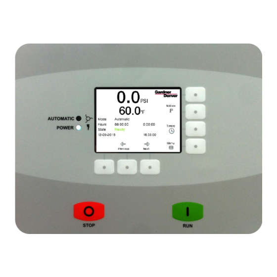
2 Controller Operation 2.1 Compressor Front Panel 2.1.1 AirSmart Controller Control Panel The Control Panel is mounted on the front panel of the compressor and is used to operate the compressor and observe system status using its 320x240 color pixel display, two status LED indicators, seven navigational buttons, and two control buttons. -
Page 10: Control Panel Indicator And General Navigation Button Functions
Figure 2-1 shows an example of the Home screen display. 2.3 Operating Screens The AirSmart G2 controller features a set of easily-accessible screens providing run-time information about the machine's operating state and condition. These are available from the home screen without logging in to the system and include sensor readings, gauges, notice history, and maintenance timer information. -
Page 11: Home Screen
2.3.1 Home Screen The home screen is the primary source of basic system status and operation. It includes plant delivery pressure and discharge temperature readings, a status indicator icon, operating mode, total and loaded hours, control state, and other dynamic information. Navigational links are provided to allow the user to access other operating screens and system menus. - Page 12 Table 2-1: Control State Definitions Control State Definition Reset The controller is resetting Auto Restart is enabled and active. The compressor will transition states at the expiration of the Auto Restart Auto Restart Timer. Shutdown A shutdown fault is active. Ready The compressor is healthy and ready to be enabled.
-
Page 13: Run Screens Carousel
· The Run Carousel Navigation buttons are labeled Previous and Next. These are used to navigate through the run screens carousel. See section 2.3.2 for more information. · Main Menu Navigation is triggered by the button labeled Menu. The menu structure and operation are described in the subsequent sections. - Page 14 The position of the needle on the gauge indicates the current pressure reading as displayed in the digital value in the center of the gauge. The yellow region on the right of the gauge begins at the current setting for the Unload Pressure and the red region on the right of the gauge begins at the Pressure Fault setting.
- Page 15 2.3.2.3 Sensor Summary Screen The final two screens in the carousel are the sensor summary and drivetrain summary screens. These screens provide a convenient display of all the sensor readings and drivetrain readings in one location. These screens can be accessed immediately from the home screen by pressing the Previous button.
-
Page 16: Notice History And Status Icon
If an advisory condition is currently active, a yellow triangle will be displayed: . To clear an advisory, press the button to the right of the Gardner Denver logo . Note that this will also navigate to the Distributor information screens to display distributor contact information and consumable part numbers. -
Page 17: Maintenance Timers Summary
Pressing the Next button will load the next notice in the log (if one exists). Pressing the Previous button will load the previous entry in the log (if one exists). The Back button will return to the home screen. The display is very similar for advisory conditions, as shown in Figure 2-9. Figure 2-9: Notice History Advisory Display 2.3.4 Maintenance Timers Summary The Maintenance Timers Summary screens can be accessed by pressing the button labeled Timers on... -
Page 18: Login And Accessibility
From the first timer summary screen, pressing the right arrow will navigate to the second screen as shown in Figure 2-11, which includes the following timers: · Oil Sample timer · Oil Change timer · Motor Lube timer Figure 2-11: Maintenance Timer Summary Notice on Figure 2-11 that the Motor Lube timer is displayed at the Expired level. - Page 19 2. From the Main Menu, select the Login button as shown in Figure 2-13. The Select User menu will appear as shown in Figure 2-14. Figure 2-13: Main Menu Figure 2-14: Select User Screen to choose the appropriate user level: Maintenance, 3.
- Page 20 Figure 2-15: Passcode Entry Screen 4. Enter the passcode for the requested access using the navigational buttons to choose the appropriate number. The Select button is used to enter the number. Navigate to and select ENTER when complete, or simply press the Enter button to apply the code. 5.
-
Page 21: Quick Start Guide
3 Quick Start Guide Quick start operation of the compressor using the AirSmart G2 can be achieved by setting the Target Pressure, setting the Load/Unload Pressures, setting the unit to Automatic Mode, and commencing run. The following steps are provided as a guide to quick starting the unit. - Page 22 2. Follow the instructions in section 2.4 to log in with distributor access. 3. From the Main Menu, use the navigational buttons and select Operational Settings. 4. Press the Enter button. The Operational Settings menu will appear as illustrated by Figure 3-3. Figure 3-3: Operational Settings Menu 5.
-
Page 23: Setting Unload Pressure
Figure 3-5: Target Pressure Menu 9. Enter the Target Pressure to the first decimal by using the navigational buttons to choose the appropriate numeric value as indicated by the white highlight (CLR in Figure 3-5). The Select button is used to enter the number or function currently highlighted. When the target pressure has been entered, navigate to and select ENTER when complete, or simply press the Enter button to apply the target pressure. -
Page 24: Setting Load Pressure
4. Enter the Unload Pressure to the first decimal by using the navigational buttons to choose the appropriate numeric value as indicated by the white highlight (CLR in Figure 3-6). The Select button is used to enter the number or function currently highlighted. When the unload pressure has been entered, navigate to and select ENTER when complete, or simply press the Enter button to apply the value. -
Page 25: Setting To Automatic Mode
3.6 Menu Structure at a Glance The following menu structure provides an at-a-glance overview of the functions and their relative location on a menu map. The AirSmart G2 controller features are organized by common functional groupings and unit settings. Chapter 5 discusses the functions of these items in detail. - Page 26 Figure 3-9: Overall Menu Structure 13-17-613 Page 25...
-
Page 27: Air Compressor Control
Each type of machine requires a certain amount of complexity for control and the AirSmart Controller can employ everything from PID control loops with specialized I/O down to simple binary (on/off) control. The following paragraphs present a brief description of how the AirSmart G2 Controller regulates pressure depending on machine type. -
Page 28: Variable Flow Compressors
System Pressure signal on units with the optional communications module that are run in Sequence mode of operation. In a typical Gardner Denver machine, the turn valve is used to control the flow between 100% and typically 40% of full capacity while the inlet valve is used to control the flow at even lower capacity levels. -
Page 29: Airsmart Controller Menus
5 AirSmart Controller Menus The AirSmart G2 Controller Main Menu is broken down into six areas of control, display, and configuration. These sub-menus are: Operational Settings, Maintenance, Alarm History, Display Options, and Machine Configuration. The Main Menu structure is organized as follows: The default values for the adjustable parameters are determined by the compressor model configuration stored in the controller’s memory. - Page 30 The Operational Settings menu structure is organized as follows: Most of the parameter settings stored in the Controller configuration that are available to be modified through the user interface can be accessed in the Operational Settings sub-menu. To enter the Operational Settings menu: 1.
-
Page 31: Operating Mode
· Sequenced: The sequenced operation of the compressor is similar to Automatic mode but the compressor is part of a sequenced group of machines. Refer to the AirSmart G2 Sequencing Manual (13-17-615) for information on operation in Sequenced mode. ·... -
Page 32: Load/Unload Setpoints
5.1.2 Load/Unload Setpoints Accessibility Maintenance Distributor Factory The Load/Unload Setpoints menu is the next category under the Operational Settings menu. These setpoints establish target and loading pressures for changing the baseline configuration of the unit. This menu gives the user the ability to change the pressure set points and the operating mode while the compressor is running or stopped. -
Page 33: Inlet Valve Control
5.1.2.4 Secondary Pressure Offset Accessibility Maintenance Distributor Factory The next item in the Load/Unload Setpoints menu is the Secondary Pressure Offset. This parameter is used to add a positive or negative offset to the Target, Load and Unload Pressure set points when a digital input programmed to the Secondary Pressures function becomes active. - Page 34 Note: The Blowdown Timer is used primarily in fixed speed compressor operations. Min Value: 1 second Max Value: 1200 seconds Default Value: 600 seconds (fixed speed units with blowdown valve) 5.1.4.2 Blowdown Counter Accessibility Maintenance Distributor Factory The next item in the Timer Setpoints menu is the Blowdown Counter, which is used to control the number of complete unload/blowdown cycles the compressor will execute.
- Page 35 5.1.4.6 Auto Restart Accessibility Maintenance Distributor Factory The next item in the Timer Setpoints menu is the Auto Restart function. If Auto Restart is enabled, the compressor will resume operation in the mode it was in prior to the power interruption when power is restored.
-
Page 36: Current Date/Time
The Current Date/Time category under the Operational Settings menu allows the user to change the Date and Time settings, which are kept by the battery-backed real time clock on the AirSmart G2 Controller. This clock is used for timestamps on logging data such as notices and trend data, as well as for AutoRun scheduling. - Page 37 5.1.6.1 Pressure Accessibility Maintenance Distributor Factory The Pressure option under the Operating Limits menu allows the user to set an advisory and shut down condition for the discharge pressure of the compressor. The maximum pressure that any compressor can achieve is set in the configuration file. If the user attempts to program a value greater than this number, the entry will be rejected and the proposed value will turn red on the numeric entry pad.
- Page 38 5.1.6.5 Plant Pressure Timeout Accessibility Maintenance Distributor Factory The next item in the Operating Limits menu is the Plant Pressure Timeout setting, which controls the length of time the plant delivery pressure value may remain under the Target Pressure setting before generating an advisory.
-
Page 39: Autorun Scheduling
5.1.7 AutoRun Scheduling The AutoRun Scheduling feature allows the user to manage the compressors run cycle via a predefined schedule. The compressor may be started and stopped based on the time settings, or a secondary pressure offset may be applied during the specified time period. The AutoRun Scheduling can be accessed through the Operational Settings menu. -
Page 40: Maintenance
5.1.7.3 AutoRun Mode Accessibility Maintenance Distributor Factory The AutoRun Mode menu allows the user to configure the behavior of the AutoRun mode, which can be set to Start/Stop mode or Secondary Pressure mode. When Start/Stop mode is selected, the compressor will be started and stopped based on the AutoRun Schedule once the user has enabled the compressor using the RUN button. -
Page 41: Maintenance Timers
5.2.2 Maintenance Timers The next item in the Maintenance menu is the Maintenance Timers. The timer settings which can be adjusted in the controller can be found in this menu. The Maintenance Timers menu structure is organized as follows: Under each sub-menu, the timer interval is displayed as well as the number of hours remaining on the timer since the last maintenance was performed. - Page 42 Figure 5-6: Timer Reset Confirmation Screen 5.2.2.2 Control Box Filter Change Timer Accessibility Maintenance Distributor Factory The next item in the Maintenance Timers menu is the Control Box Filter Change Timer. This value sets the default control box filter change countdown timer. Setting this parameter to zero will disable the timer and its associated alarms.
-
Page 43: Distributor Information
5.2.2.1 Oil Sample Timer Accessibility Maintenance Distributor Factory The next item in the Maintenance Timers menu is the Oil Sample Timer. This value sets the default oil sample countdown timer value. Setting this parameter to zero will disable the timer and its associated alarms. -
Page 44: Consumables
The Consumables screen is the next item under the Maintenance menu. This screen provides an easy reference to the Gardner Denver part numbers for consumable items specific to the package, such as filters, oil, and transducers. These entries may be modified as required by Distributor and Factory level users. - Page 45 An example of the first page is shown in Figure 5-8 below. Figure 5-8: Temperatures Screen Selecting VFD 1, VFD 2, or VFD 3 will yield three pages that display drivetrain data of the compressor. The first page shows the min and max frequencies of the drivetrain, motor frequency, motor speed, etc. The second page shows the voltage, current, power, etc.
-
Page 46: Display Options
5.3 Display Options The Display Options menu allows the user to review options related to the display of the controller. The Display Options menu structure is organized as follows: To enter the Display Options menu: 1. From the Home screen, press the Menu button. 2. -
Page 47: Machine Configuration
5.4 Machine Configuration The Machine Configuration menu allows the user review and configure details about the compressor related to model, hours run, motor power and other similar functions. The Machine Configuration menu structure is organized as follows: To enter the Machine Configuration menu: 1. -
Page 48: Drive Train
5.4.1.4 Oil Type Accessibility Maintenance Distributor Factory The next item in the Compressor Menu selects the Oil Type. The Oil Type setting determines how fast the Oil Change Timer will count down as the compressor discharge temperature rises as shown in the table below. The Oil Type selections are as follows. Default Value: Compressor model dependent ·... - Page 49 5.4.2.1 Starter Type Accessibility: Maintenance Distributor Factory The Starter Type menu displays what starter unit variation is implemented in the current machine. The starter type will be one of full voltage, wye delta, or none. 5.4.2.2 VFD Accessibility Maintenance Distributor Factory The next item in the Drive Train menu is the VFD menu.
- Page 50 5.4.2.2.4 Elevation Accessibility Maintenance Distributor Factory The next item in the VFD menu is Elevation. Elevation should be set equal to the elevation above sea level at the compressor site. This parameter is used to de-rate the compressor drive system at higher elevations where heat dissipation is less effective. There is no de-rating performed at elevations below 3300 feet (1000 m).
- Page 51 5.4.2.2.9 VFD 1 Accessibility Maintenance Distributor Factory The next item in the VFD menu is the VFD 1 menu. The VFD 1 menu allows the user to configure the settings of VFD 1. The VFD 1 menu structure is organized as follows: 5.4.2.2.9.1 Drive Type Accessibility Maintenance...
- Page 52 5.4.2.2.9.5 Min & Max Speeds Accessibility Maintenance Distributor Factory The last two items in the VFD 1 menu is the Min Speeds and Max Speeds. The Min and Max Speeds relate to the preset pressures that are set in the Pressure Bands section previously. The minimum and maximum speed can be set for pressures P1 –...
- Page 53 5.4.2.5 Star to Delta Time Accessibility Maintenance Distributor Factory The Star to Delta Time setting controls dwell time between wye and delta connections. Do not change this setting without direct instruction from Gardner Denver Engineering. 5.4.2.6 Motor Current(s) Accessibility Maintenance Distributor Factory The next item in the Drive Train menu is the Motor Current consumption value of each individual motor in the system.
-
Page 54: Enclosure
5.4.2.9 PID Setup Accessibility Maintenance Distributor Factory The last item on the Drive Train menu is the PID Setup. PID1, PID2, and PID3 control different elements of the compressor depending on what the package is configured for. Table 5-2 below shows what each of the PID values control for variable speed and fixed speed compressors. -
Page 55: Airsmart Controller
Figure 5-10. Figure 5-10: AirSmart Controller Versions Screen The top right button on the AirSmart Controller screen allows the distributor level user to update the screens, configuration file, fonts, and firmware, if necessary. Software updates are loaded from the SD card and must be provided by Gardner Denver service or engineering. -
Page 56: Calibrate Sensor
5.4.5 Calibrate Sensor Accessibility Maintenance Distributor Factory The Calibrate Sensor screen allows fine tuning of the pressure sensors used with the system as shown in Figure 5-12. These values should only be adjusted if a sensor is consistently offset by a small amount when there is zero pressure in the system. -
Page 57: I/O Mapping & Diagnostics
The Communications menu structure is organized as follows: Refer to the AirSmart G2 Modbus Manual (13-17-617) for more information on communications and the required settings. 5.4.7 I/O Mapping & Diagnostics The I/O Mapping & Diagnostics menu allows the user to review the hardware address locations of the various input and output devices for troubleshooting and diagnosing system problems. - Page 58 To calculate the address corresponding to a particular port, multiply the Unit Number from the table above by 16, then add the number of the IO port function. For example the address for Digital input 3 on the expansion module is: (16 x 2) + 3 = 36. Note that for digital inputs and outputs, a negative number in the address corresponds to an active low signal, whereas a positive number in the address corresponds to an active high signal.
- Page 59 The machine data available for review is shown in Figure 5-15, 5-16, and 5-17 below. Figure 5-15: Machine Data Temperatures Figure 5-16: Machine Data Pressures Figure 5-17: Machine Data Pressures Continued The drivetrain data allows the user to review the minimum, maximum, command, and current motor frequency as well as the motor speed, along with motor current, voltage, power and other drivetrain data.
- Page 60 Figure 5-18: Drivetrain Data (Page 1) Figure 5-19: Drivetrain Data (Page 2) Figure 5-20: Drivetrain Data (Page 3) 13-17-613 Page 59...
- Page 61 Note: This feature is only available on machines with a variable speed drive. The Hardware Tests that are available include: Button Test: validation of physical button depress functionality Core DIN Test: Display of digital value at each digital input Core DOUT Test: Send digital signals to available digital outputs Core AIN Test: Display signal value at each analog input Figure 5-21 shows an example screen of the hardware tests described above.
-
Page 62: Multi-Machine Sequencing
The parameter that can be set in this menu are capacity, number of units, unit number, transfer interval, lag start delay, transfer load increment, transfer load decrement, and sequence time offset. See the AirSmart G2 Sequencing Manual (13-17-615) for detailed information on sequencing operation. - Page 63 5.4.8.3 Unit Number Accessibility Maintenance Distributor Factory The Unit Number is a number between one and eight that is assigned to each compressor in the sequence. This value is used to identify compressors on the network. No two compressors can share the same unit number.
-
Page 64: Oil Control Setup
The Oil Control Setup menu structure is organized as follows: Caution: These parameters are not available in all compressor packages and should not be adjusted unless directed by Gardner Denver unit control personnel. 5.4.9.1 Oil Control Method Accessibility... -
Page 65: Control Pressure
Table 5-4: Oil Control Parameter Definitions Injection Delta T Parameter A VC Low Oil Temp Valve Max CMD Parameter B V1 High Oil Temp Valve Min CMD Parameter C V2 Low Oil Temp Valve PID Gain Parameter D V2 High Oil Temp Valve PID Int Time Parameter E Full Flow Start Time... -
Page 66: Motor Jog
5.4.10.2 Restart Pressure Accessibility Maintenance Distributor Factory The next item in the Control Pressure menu shows the current value of the Restart Pressure setting which reflects the maximum pressure allowed in the air/oil reservoir at which the compressor will be allowed to start or restart. -
Page 67: Error Management
6 Error Management The AirSmart G2 controller has the ability to read many analog inputs and control a host of digital I/O in order to achieve system objectives. To that end, there are numerous tests that are performed every second by the AirSmart G2 controller in order to determine the state of the compressor system. Many of those tests are designed to check if certain parameters have been exceeded so that action can be taken to protect the machine. -
Page 68: Shutdown Faults
6.2 Shutdown Faults The shutdown faults in the AirSmart G2 controller are designed to protect the compressor from component failure or extreme environmental conditions. Shutdown faults can be reset after the compressor has stopped by pressing the STOP button. If the error condition still exists, the shutdown fault cannot be reset. - Page 69 Table 6-3: Shutdown Fault Definitions Shutdown Condition Description Action Communications failure between Check wiring or mixing valve Actuator Comm Error controller and precision mixing operation valve Differential pressure over Change Separator separator element > 15 PSIG (1 Change separator element bar) Cooler Aux input does not match Cooler Aux...
- Page 70 Table 6-3: Shutdown Fault Definitions Cont. Shutdown Condition Description Action Connection to thermistor TT3 is Check wiring between thermistor Open TT3 open TT3 and controller Connection to pressure transducer Check wiring between pressure Open XD1 PT1 is open transducer PT1 and controller Connection to pressure transducer Check wiring between pressure Open XD2...
- Page 71 Table 6-3: Shutdown Fault Definitions Cont. Shutdown Condition Description Action Check oil pressure and for sources Low Oil Pressure Oil pressure < alarm set point of high system pressure Plant delivery temp > alarm set Check plant delivery temp or High Plant Delivery Temp point reduce package power...
- Page 72 Table 6-3: Shutdown Fault Definitions Cont. Shutdown Condition Description Action Connection to expansion module Check wiring between expansion Open EXP TT5 TIN5 is open module TIN5 and controller Connection to expansion module Check wiring between expansion Shorted EXP TT5 TIN5 is shorted module TIN5 and controller Digital input for enclosure temp Check the enclosure temperature...
-
Page 73: Data Logs
7.1 Format Data Logs can be found on the SD card in the memory card slot on the side of the AirSmart G2 controller. The log files are located in the DataLogs folder on the SD card, which can be accessed by temporarily removing the SD card from the controller and using an SD card reader to copy the files from the SD card to another device, such as a PC. - Page 74 Table 7-1: Controller States Value State Value State Reset Auto Restart Delta Shutdown Start Ready Pause Remote Halt Loaded Ask to Start Unload Enabled Blowdown Ask to Load Normal Stop Pre-Wye Table 7-2: Operating Modes Operating Mode Designation Constant Low Demand Automatic Sequenced Connect 12...
- Page 75 Table 7-3: Advisory Codes Value Advisory Code Value Advisory Code Value Advisory Code High Inlet System OK High Vibration Pressure Air Filter Timer Air Filter Timer Low Oil Level 1 Oil Filter Timer Oil Filter Timer Low Oil Level 2 High Enclosure Oil Sample Timer Change Separator...
- Page 76 Table 7-4: Fault Codes Value Fault Code Value Fault Code Value Fault Code Low Ambient System OK Motor Over temperature Temperature High Differential Hardware Fault Fan Fault Temperature High Differential SD Card Error Phase Sequence Temperature Rate High Enclosure Configuration Error Low Voltage Relay Temperature High Enclosure...
-
Page 77: Technical Data
9.0 in x 7.5 in x 1.8 in 228.6 mm x 190.5 mm x 45.7 mm 8.2 Agency Certifications The AirSmart G2 controller is a UL Recognized component in the United States and Canada. 8.3 Environmental Ratings Operating temperature range: -40°F to 185°F (-40°C to 85°C) Storage temperature range: -40°F to 185°F (-40°C to 85°C) - Page 78 NOTES:...
- Page 79 NOTES:...
- Page 80 For additional information, contact your local representative or visit: www.contactgd.com/blowers ©2017 Gardner Denver, Inc. Printed in U.S.A.
Need help?
Do you have a question about the AirSmart and is the answer not in the manual?
Questions and answers