
Related Manuals for PSC POWER STAR ELEMENT


Summary of Contents for PSC POWER STAR ELEMENT
- Page 1 PSC POWER STAR ELEMENT Operation Manual Version 1.0 Copyright 2020 Professional Sound Corp 28085 Smyth Drive, Valencia, CA 91355 USA CE RoHS Printed in the U.S.A.
- Page 2 BATTERIES WITH GREAT CAUTION. ALL AUXILARY EQUIPMENT SHOULD BE REVERSE POLARITY PROTECTED AND PROPERLY FUSED AT ALL TIMES. THE POWER STAR ELEMENT IS DESIGNED FOR USE WITH EITHER A SEALED LEAD ACID CHEMISTRY BATTERY OR WITH A LiFEPO4 (LITHIUM IRON PHOSHATE) BATTERIES ONLY. THE SUPPLIED CHARGER IS...
- Page 3 SLA battery to use with the device when you arrive at your location shoot. This eliminates having to deal with shipping any lithium batteries. Never ship your PSC PowerStar Element while it is attached to any battery! It must be removed (un-installed) from the battery before shipping the unit.
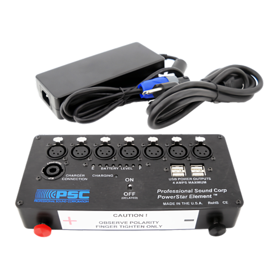
- Page 4 FRONT PANEL: The front panel of the PSC PowerStar Element contains seven (7) DC power output connections on 4 pin female XLRs. A SpeakOn connector is used to connect the unit to the supplied external battery charger. A Multi Colored LED “Fuel Gauge” to indicate battery charge level. A Power “ON”...
- Page 5 BATTERY RECOMMENDATIONS AVAILABLE ON AMAZON AS OF DATE OF MANUAL PUBLICATION: SEALED LEAD ACID (SLA): Power Sonic #PS-12350814 Post Terminal Style Universal Power Group #D5722 UB12350 Post Terminal Style Mighty Max Battery #ML35-12 SLA Post Terminal Style Interstate Battery #SLA1155 Post Terminal Style MOUNTING THE POWERSTAR ELEMENT TO THE BATTERY: IT IS EXTREMELY IMPORTANT THAT YOU READ AND THOROUGHLY UNDERSTAND THESE...
- Page 6 5. Carefully note the orientation of the PSC PowerStar Element in relationship to the battery terminals. There is a colored sticker on the front edge of the PSC PowerStar Element to help you locate the unit correctly over the terminals. The Positive (RED +) terminal on the battery must connect to the Positive terminal on the PowerStar Element.
- Page 7 RED and BLACK Thumb Screw Caps seat flush to the front edge of the Power Star Element. You may now fully tighten the thumb screws. The thumb screws should be fully tightened down with adequate thumb pressure to insure good electrical contact between the battery contact and the battery terminal.
- Page 8 Thumb screws installed and finger tightened. BATTERY CHARGER HEAT DISSIPATION: The PSC Power Star Element uses an external 10-amp battery charger. This charger will get quite warm in use. You must provide adequate airflow around the charger so that is can properly dissipate the heat given off while charging. Do not operate the charger with the charger fully enclosed such as in a drawer, or packed tightly within other equipment.
- Page 9 DC CONNECTIONS: There are seven (7) XLR female DC output connectors located on the front panel of the PSC Power Star Element. The first six (6) XLRs located to left hand side of the unit are rated for 3 Amps of output current. The remaining XLR output connector is rated for 5 Amps of output current.
- Page 10 BATTERY LEVEL “FUEL GAUGE”: The PSC PowerStar Element is equipped with an easy to read and easy to understand multi-colored battery “Fuel Gauge”. Just a quick glance and you will immediately know the charge condition of your battery. A full row of Green LEDs indicated a fully charged battery.
-
Page 11: Charger Connector
8AWG wire. This cable will allow you to mount the Power Star Element in a separate location from your battery and it will allow the unit to be connected to batteries that do not have standard terminal spacing. The cable comes complete with a set 6mm screws for use on metric “post less”... - Page 12 Cable before attachment Cable attached to Power Star Element EQUIPMENT POWER CABLES: PSC recommends that you use only two conductor, unshielded 16AWG power cable for power distribution. Shielded cable is not recommended as the shield may cause short circuits between adjacent pins on the connectors. Please keep all cables as short as possible as this will minimize DC voltage drop across the cable.
-
Page 13: Battery Storage
Our competitors do not understand inter-modulation noise and thus do not take the additional steps to prevent it like we do at PSC. Though not every piece of equipment will suffer from inter-modulation noise issues. Here at PSC we believe that the extra parts cost and design time are worth it if it solves even one issue in the field. - Page 14 AND/OR EQUIPMNET CONNECTION AND/OR BATTERY CHARGER CONNECTION, AND/OR INSTALLATION, IMPROPER ELECTRICAL CONTACT AND/OR IMPROPER GROUNDING. OWNERSHIP AND/OR USE OF THE PSC POWER STAR LiFE CONSTITUTES AGREEMENT WITH THESE TERMS. Limited Warranty Certificate Professional Sound Corporation warrants the PowerStar Element to be free from defective...
-
Page 15: Specifications
Specifications: SPECIFICATIONS, MAIN UNIT: SIZE: 8.00” W, 4.00” D, 1.50” H (20.3cm x 10.2cm x 3.8cm) WEIGHT: 1.3Lbs (590g) TEMPERATURE RANGE: -4F to +124F (-20C to +50C) XLR OUTPUTS: 6 x 3Amp, 1 x 5Amp USB POWER OUTPUTS: 4 Ports, Total Output 5Vdc at 4 Amps OUTPUT VOLTAGE: 12.8Vdc Nominal OUTPUT CURRENT:... -
Page 16: Declaration Of Conformity
DECLARATION OF CONFORMITY EMC: This product is in compliance with the Electromagnetic Compatibility Directive, 89/336/EEC as defined in EN 50081-1, EN55022 and EN 50082-1. IEC801-2, IEC801-3 and IEC801-4. LVD: This product is in compliance with the requirements of the Low Voltage Directive, 73/23/EEC.
Need help?
Do you have a question about the POWER STAR ELEMENT and is the answer not in the manual?
Questions and answers