Table of Contents
Advertisement
Quick Links
Advertisement
Table of Contents

Related Manuals for Exhausto EXact2


Summary of Contents for Exhausto EXact2
- Page 1 EXact2_VEX300 3004811-2018-09-14 EXact2 control system Basic instructions VEX320-370/CX340-350/ VEX310T-350T CX300 EXHAUSTO EXHAUSTO Original instructions EXHAUSTO A/S Tel. +45 65 66 12 34 Odensevej 76 Fax: +45 65 66 11 10 DK-5550 Langeskov exhausto@exhausto.dk www.exhausto.dk...
- Page 2 3004811-2018-09-14 Menu structure User menu: Technician and service menu: 1 Operating mode Main menu Manual Operation > Operating mode > Operating readings > °C Settings > 2 Operating readings Alarm and info > Time and weekly plan > Air temperature > Versions >...
-
Page 3: Table Of Contents
3004811-2018-09-14 Symbols and software version Symbols used in these instructions..............6 Software version....................6 Software version ..................... 6 1. User mode 1.1. HMI panel........................ 7 1.2. Display icons......................8 2. Operation, access codes and selecting language 2.1. Using the HMI panel.....................10 2.1.1. - Page 4 3004811-2018-09-14 Menu 3.1.2 - Air compensation................42 Menu 3.1.2.1 - CO2 compensation ............... 43 Menu 3.1.2.2 - Humidity compensation of airflow ......... 44 Menu 3.1.2.3 - Airflow reduction ..............44 Menu 3.1.2.4 - Outdoor compensation of airflow .......... 45 Menu 3.1.3 - Temperature compensation............46 Outdoor air temperature compensation (menu 3.1.2.1) ........
- Page 5 3004811-2018-09-14 VEX320R ....................106 VEX330CL....................107 VEX330CR....................108 VEX330HL....................108 VEX330HR....................109 VEX340L ..................... 109 VEX340R .....................110 VEX350L - VEX360L ...................110 VEX350R- VEX360R ...................111 VEX370L HCWi.................... 111 VEX370R HCWi................... 111 VEX370L ..................... 112 VEX370R .....................112 CX340/350....................113 VEX310TR-VEX350TR................114 VEX310TL-VEX350TL................. 115 Appendix 2 - Temperature resistance table Temperature resistance table DC95..............
-
Page 6: Symbols And Software Version
Symbols and software version 3004811-2018-09-14 Symbols and software version Symbols used in these instructions Prohibition symbol Failure to observe instructions marked with a prohibition symbol may result in serious or fatal injury. Danger symbol Failure to observe instructions marked with a danger symbol may result in personal injury and/or damage to the unit. -
Page 7: User Mode
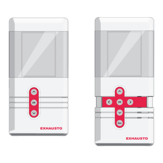
Display Browse menu or set value Activate menu/confirm key Browse menu or set value mode EXHAUSTO If the front cover is extended, push it back in. The extra keys are for service tech- nician use only. EXHAUSTO EXHAUSTO 7/120... -
Page 8: Display Icons
User mode 3004811-2018-09-14 1.2 Display icons Icon Description Manual operation Timer overridden until next changeover in the timer schedule Timer, current indoor air quality level is comfort Timer, current indoor air quality level is economy Timer, current indoor air quality level is standby Timer, VEX/CX has stopped Timer, no changeover times defined in timer schedule BMS-controlled operation... - Page 9 User mode 3004811-2018-09-14 Icon Description External start/stop disconnected. See Electrical Installation Guide for further information Summertime Wintertime No communication on the external BUS or communication between the VEX/CX and HMI is disconnected Fire alarm. Closed circuit open and the pre-set fire alarm function acti- vated Fire! Startup: Web server accessing database.
-
Page 10: Operation, Access Codes And Selecting Language
3004811-2018-09-14 language 2. Operation, access codes and selecting language 2.1 Using the HMI panel Keys for user mode or service mode EXHAUSTO EXHAUSTO HMI panel ready for every- HMI panel ready for service mode day use Display Service key cover 2.1.1 Using keys within the menus... -
Page 11: Access Codes For Technician And Service Menus
1111 code. ● The code for technician mode is1111 (some menus are hidden or read-only). EXHAUSTO recommends this mode is used for normal service tasks ● The code for specialist mode is 3142 (full ac- cess to all menus). -
Page 12: Important When Servicing
Operation, access codes and selecting 3004811-2018-09-14 language 2.3 IMPORTANT when servicing Do not open the service doors before the supply voltage has been disconnec- ted at the isolation switch. The isolation switch is located on the connection box, see illustration. 12/120... -
Page 13: Auxiliary Service Panel
OFF function and the VEX/CX may start up irreg- server ularly. To disconnect the BMS or WEB server connec- tion, you must remove the plug from the EXact2 main board. Refer to the section on the terminal board in the Electrical Installation Guide. - Page 14 Operation, access codes and selecting 3004811-2018-09-14 language Example, Horizontal VEX300 Auxiliary service panel which overrides the fixed HMI panel Fixed HMI-panel Service panel con- nector - Exact2 Cable requirements The service panel cable can be ordered from EXHAUSTO (product number: HMI- SERVICEC). 14/120...
-
Page 15: Menu 3.2 - Selecting Language
Operation, access codes and selecting 3004811-2018-09-14 language Menu 3.2 - Selecting language 3 Settings 3.2 General Main menu Operating mode > Unit > Date and time > Operating readings > General > Language > English Settings > Configuration > Reset settings > Alarm and info >... -
Page 16: Menu 3.2 - Reload Database
Operation, access codes and selecting 3004811-2018-09-14 language Menu 3.2 - Reload database Selecting "Reset settings" resets the user settings. See the menu guide for details of which menus are affected. Database reloads Initialising Loading DB names Menu 3.6 - Web server Contact the network administrator for information on the correct IP address, etc. -
Page 17: Menu 3.7 - Backup/Restore
Operation, access codes and selecting 3004811-2018-09-14 language Menu 3.7 - Backup/restore It is recommended that a backup copy of the VEX/CX settings is made and saved on a secure media. See the individual backup guidelines in the diagram: Backup via the HMI panel ●... -
Page 18: Starting Up The Unit For Operation
Starting up the unit for operation 3004811-2018-09-14 3. Starting up the unit for operation The Modbus connectors must not be connected or removed while the units are powered up. Both Modbus units must be switched off before making changes, otherwise the units may be damaged. During commissioning, it may be necessary to work with the control system boxes open. -
Page 19: Start Configuration
Starting up the unit for operation 3004811-2018-09-14 Start configuration Step Action Check that the correct configuration for the VEX/CX has been se- lected at the factory via menu 3.3. Check that all accessories have been configured in menu 3.4 If a CO sensor is installed, check in Menu 3.1.2.1 "CO compensa- tion"... -
Page 20: Menu 3.4 - Accessories
VEXCX type and associated de-icing methods are described. Heating coil Options: ● IHCW (set at the factory for the the EXact2 main board, if the VEX/CX was purchased with HCW) ● MHCE (Electric heating coil) ● MHCW (Water heating coil) ●... - Page 21 Starting up the unit for operation 3004811-2018-09-14 Line in Menu 3.4 Factory-set and Remarks: should not be changed. Activating PIR sensor. Op- tions: ● Both (Both MIOPIR and PIRB connected) ● PIR2 (PIRB connected) ● PIR1 (MIOPIR connected) ● None When the sensor(s) is/are acti- vated by movement in the room, the VEX/CX will be...
-
Page 22: Menu 3.4 Connecting Heating And Cooling Units
Starting up the unit for operation 3004811-2018-09-14 Menu 3.4 Connecting heating and cooling units Location A heating coil and a cooling unit can be connected to the VEX/CX. The example below (VEX340) shows the position of the coils in relation to the VEX unit. Cooling unit - Heating coil. -
Page 23: Temp.controlled Frost Protection - Selection Of Method Vex320-330/ Vex310T-350T
Starting up the unit for operation 3004811-2018-09-14 3.3 Temp.controlled frost protection - selection of method VEX320-330/ VEX310T-350T Heating coil METHOD 4 METHOD 6 The outdoor air gradually bypasses the heat exchanger The outdoor air is The outdoor air is gradually reduced gradually reduced The unit enters The unit enters... -
Page 24: Press. Controlled Frost Protection - Selection Of Method Vex320-330/ Cx340-350/Vex310T-350T
Starting up the unit for operation 3004811-2018-09-14 3.4 Press. controlled frost protection - selection of method VEX320-330/ CX340-350/VEX310T-350T Heating coil Is an imbalance acceptable? METHOD 4 METHOD 5 METHOD 6 The outdoor air gradually The outdoor air gradually bypasses the heat exchanger bypasses the heat exchanger The outdoor air is The outdoor air and... -
Page 25: Vex 350-370 De-Icing Methods
Starting up the unit for operation 3004811-2018-09-14 Selecting VEX340 method Is an imbalance acceptable? Is reduced extraction during de-icing acceptable? METHOD 1 METHOD 2 METHOD 3 Return air is activated and Return air is activated and gradu- Return air is activated and gradually increased to 30 % ally increased to 30 % –... -
Page 26: Selecting Method For Vex350/360/370
Starting up the unit for operation 3004811-2018-09-14 Selecting method for VEX350/360/370 Heating coil Is an imbalance acceptable? METHOD 4 METHOD 5 METHOD 6 The outdoor air gradually The outdoor air gradually bypasses the heat exchanger bypasses the heat exchanger The outdoor air and extract air are gradually The outdoor air is The outdoor air is... -
Page 27: Menu 3.5 Bms
Starting up the unit for operation 3004811-2018-09-14 Menu 3.5 BMS Menu 3.5 - BMS 3.5 BMS Line in Menu 3.5 Comments BMS > None Configuration > Activating override control system BMS Op- tions: ● None ● Modbus ● MTCP ● MLON ●... -
Page 28: Menu 1 - Selecting Operating Mode
HMI panel or the Web server Timer The unit is controlled automatically via a fixed weekly plan Note during com- EXHAUSTO recommends that the operating mode be set to Manual during com- missioning missioning and changed to Timer operation when complete. NB: for manual When the unit is operating in Manual air quality level, the temperature set point (Temp. - Page 29 Starting up the unit for operation 3004811-2018-09-14 Method Meth- Description Following parameters are Menu od no. (1-8) Manual con- Constant speed ● Balance 3.1.1 Operating settings trol IAQ. levels > Manual control of fan speed Temp. reg. > Supply air Air reg.
-
Page 30: Menu 3.1.1 - Operating Settings Balance
Starting up the unit for operation 3004811-2018-09-14 Method Meth- Description Following parameters are Menu od no. (1-8) Constant pressure regulated ● Supply airflow values 3.1.1.4 Constant pressure supply air with slave-control- for maximum and min- Supply air: led extract air imum ventilation Setp. -
Page 31: Menu 3.1.1.5 Regulators
Starting up the unit for operation 3004811-2018-09-14 Example of balance The examples show a unit with manual fan control and balances of 0.80 and 1.20 respectively. Range The required airflow is outside the unit’s normal operating range balanced unbalanced Less than 1 = less supply air - Greater than 1 = less extract air Note for methods 3, Balance is not active for air regulation methods 3, 4, 7 and 8. -
Page 32: Menus 3.1.1.1.1 To 3.1.1.1.4 Configuring The Indoor Air Quality Levels
Starting up the unit for operation 3004811-2018-09-14 Kp and Ti settings should only be changed by persons trained in commissioning ventilation systems. If the following is selected Permitted operations Technician mode (code 1111) Read the settings for the vari- ous regulators Specialist mode (code 3142) Set Kp and Ti for the various regulators... -
Page 33: Menu 3.1.1.1.X - Cooling Relative Start
Starting up the unit for operation 3004811-2018-09-14 Menu 3.1.1.1.x - Cooling relative start Definition This value determines when cooling must start in relation to the relative tempera- ture. Low value = narrow temperature regulation range, leading to a comfortable indoor climate. High value = wider temperature regulation range, which provides cooling energy savings. -
Page 34: Menu 3.1.1.1.X - Heating Absolute Start
Starting up the unit for operation 3004811-2018-09-14 Example If Cooling abs. start is set to 24°C, the cooling unit will first start to operate when the temperature exceeds 24°C, even though the daily user has set the required room temperature to 21°C. Menu 3.1.1.1.x - Heating absolute start Definition This value determines when heating must start in relation to the absolute tempera-... - Page 35 Starting up the unit for operation 3004811-2018-09-14 Max. and Min. may never be set closer to each other than 1K. If the following temperature will be is selected controlled by... supply air regula- supply air temperature Supply air temperature will never tion be higher than "Maximum"...
-
Page 36: Menu 3.1.1.1.X - Supply Air Regulation, Absolute
Starting up the unit for operation 3004811-2018-09-14 Menu 3.1.1.1.x - Supply air regulation, absolute 3.1.1.1.x xxxxxxx Air setpoint > °c Air setpoint,cool Temp. setpoint > 21,0 Abs. / Rel. > Absolute Cool rel. start > °c Cool abs. start > 26,0 Heat rel. -
Page 37: Menu 3.1.1.1.X - Room Temperature Regulation, Absolute
Starting up the unit for operation 3004811-2018-09-14 Menu 3.1.1.1.x - Room temperature regulation, absolute 3.1.1.1.x xxxxxxx Air setpoint > °c Air setpoint,cool Temp. setpoint > 21,0 Abs. / Rel. > Absolute Cool rel. start > °c Cool abs. start > 26,0 Heat rel. -
Page 38: Menu 3.1.1.1.X - Supply Air Regulation, Relative
Starting up the unit for operation 3004811-2018-09-14 Menu 3.1.1.1.x - Supply air regulation, relative 3.1.1.1.x xxxxxxx Air setpoint > Air setpoint,cool > Temp. setpoint > 21,0 °c Abs. / Rel. > Relativ Cool rel. start > Cool abs. start > Heat rel. - Page 39 Starting up the unit for operation 3004811-2018-09-14 Example 2: Minimum and Maximum supply air temp. limit Cooling rel. start and Heating rel. start: 39/120...
-
Page 40: Menu 3.1.1.1.X - Room Temperature Regulation, Relative
Starting up the unit for operation 3004811-2018-09-14 Menu 3.1.1.1.x - Room temperature regulation, relative 3.1.1.1.x xxxxxxx Air setpoint > Air setpoint,cool > Temp. setpoint > 21,0 °c Abs. / Rel. > Relativ Cool rel. start > Cool abs. start > Heat rel. -
Page 41: Menu 3.1.1 - Operation Settings - Temperature Regulation
Starting up the unit for operation 3004811-2018-09-14 Example 2: Minimum and Maximum room temp. limit Cooling rel. start and Heating rel. start: Menu 3.1.1 - Operation settings - Temperature regulation Select one of two temperature regulation methods: ● Supply air temperature regulation ●... -
Page 42: Compensation
Starting up the unit for operation 3004811-2018-09-14 ● Modulating heating coil(s). ● Any external cooling unit and cooling recovery Select Select one of the following: ● Supply air regulation - Typically used when the unit serves several rooms with different loads (sunlight, people, machines). The temperature is regula- ted by the built-in temperature sensor in the supply air spigot. -
Page 43: Menu 3.1.2.1 - Co2 Compensation
Starting up the unit for operation 3004811-2018-09-14 ● All compensation options can be connected and active at the same time, and may influence the control airflow ● CO and humidity compensation cannot be activated if air regulation method 8 is selected. Autostart with timer If the weekly schedule is at OFF and either the CO or the humidity level exceeds... -
Page 44: Menu 3.1.2.2 - Humidity Compensation Of Airflow
Starting up the unit for operation 3004811-2018-09-14 Menu 3.1.2.2 - Humidity compensation of airflow Requirements A humidity sensor (RHB, MIO-RH, BMS) must be fitted in order to be able to se- lect humidity compensation of the airflow. The sensor must be installed in the room in which you wish to make compensation, such as a bathroom. -
Page 45: Menu 3.1.2.4 - Outdoor Compensation Of Airflow
Starting up the unit for operation 3004811-2018-09-14 Example Supply air temperature is Airflow... Lower than Minimum Equivalent to Minimum (or lowest) airflow Between Minimum and Start increases gradually between mini- mum airflow and the set airflow Greater than Start Equivalent to set airflow ●... -
Page 46: Menu 3.1.3 - Temperature Compensation
Starting up the unit for operation 3004811-2018-09-14 Outdoor air temperature is Airflow... Lower than Minimum Equivalent to Minimum airflow Between Minimum and Start increases gradually between mini- mum airflow and the set airflow Greater than Start Equivalent to set airflow Menu 3.1.3 - Temperature compensation Outdoor air temperature compensation (menu 3.1.2.1) Function... -
Page 47: Summertime Compensation (Menu 3.1.2.2)
Starting up the unit for operation 3004811-2018-09-14 Summertime compensation (menu 3.1.2.2) Function The room temperature can be raised if outdoor air temperatures are high. Summertime compensation is active only if room temperature regulation is activa- ted for the indoor air quality level in Menu 3.1.1 (Operation settings -> Temp. reg. - >... -
Page 48: Menu 3.1.4 + Menu 8.1 - Filter (Monitoring With Hour Counter)
Starting up the unit for operation 3004811-2018-09-14 Current pressure The current pressure drop across the outdoor air and extract air filters is dis- played. Warning Set the supply air and extract air soiled-filter warning level here. Alarm Set the outdoor air and extract air replace-filter alarm level here. Menu 8.1 The same settings that can be configured in Menu 3.1.4 can be configured here. - Page 49 Starting up the unit for operation 3004811-2018-09-14 ● Outdoor air temperature must be lower than the room temperature ● Prior to initiating night-time cooling, there must not have been any heating re- quirement within a time interval defined in the night-time cooling menu ●...
- Page 50 Starting up the unit for operation 3004811-2018-09-14 3.1.5 Night-time cooling 3.1.5.9 Permit night-time cooling Active period > Summer Comfort > Set point > 18°C Standby > Min. supply temp. > 10°C Economy > ΔT max. > ΔT min. > Start time > 00:00 Stop time >...
-
Page 51: Menu 3.1.6 - Cold Recovery
Starting up the unit for operation 3004811-2018-09-14 *The extract air temperature is always used, regardless of whether a room tempera- ture sensor is installed for the system. Menu 3.1.5.9 - Per- mit night-time cool- is set to and the indoor air quality is activated level is Comfort/Standby/... -
Page 52: Room Temperature Limits
Starting up the unit for operation 3004811-2018-09-14 Supply air tempera- ture limits Setting Go to menu Lowest permitted supply air tempera- 3.1.8 Range: 10.0℃... ture 25.0°C Highest permitted supply air tempera- Range: 30.0℃... ture 40.0°C The settings above must only be changed if special circumstances require this. -
Page 53: Menu 5 - Time And Weekly Plan
Starting up the unit for operation 3004811-2018-09-14 Menu 5 - Time and weekly plan Menu 5.1 - Date and time This menu is used to set the current date, day and time. Menu 5.2 - Weekly plan Plan type When "Timer" operation has been selected in Menu 1, the weekly plan must be configured. -
Page 54: Menu 7 - Safety Functions
Starting up the unit for operation 3004811-2018-09-14 Program example 5.2.2.1 Weekday 1 IAQ. level > Standby 1 Time of day > 06:00 2 IAQ. level > Comfort 2 Time of day > 07:30 3 IAQ. level > Economy 3 Time of day > 17:30 4 IAQ. -
Page 55: Menu 7.2 - Frost Protection Of Hcw
Activation of oper- The selected operating mode under the function "Fire alarm" is activated if the ating mode closed circuit in any of the two inputs Fire and AUX IN on EXact2 main board are broken. The inputs allow the connection of: ●... -
Page 56: Menu 7.3 - Frost Protection Heat Exchanger
Starting up the unit for operation 3004811-2018-09-14 Stop temperature If the return water tem- and total Response perature does the fol- number of lowing within a five-mi- restarts nute period Rises above the constant > 0 Airflow is increased again to the nor- heating temperature mal operating level Remains below the con-... - Page 57 Starting up the unit for operation 3004811-2018-09-14 Fine adjustment of As ice formation in the counter flow heat exchanger is strongly dependent on the humidity content of the extract air, the air temperatures and the air volumes, it is recommended that the unit is fine-adjusted once it has been brought into use. Fine adjustment of T can reduce annual energy consumption.
-
Page 58: Operation
Operation 3004811-2018-09-14 4. Operation Menu 2 - Operating readings General All of the operating parameters can be read in Menu 2. _ _ _ is shown in the menu if a given unit is not fitted. Menu 2.1 - Air temperatures 2 Operating readings 2.1 Air temperature 2.1.1 Setp. -
Page 59: Menu 2.1.1 - Set Points For Regulators
Operation 3004811-2018-09-14 Example VEX300 + Chiller Diagrams See appendix 1 for VEX320/330/340/350/360/370-CX340/350-VEX310T-350T. Menu 2.1.1 - Set points for regulators This menu shows set points for: 2.1.1 Setp. regulators ● Room temperature regulator Room 10,0 Heat recovery ● Heat recovery regulator 10,0 Cooling unit 10,0... -
Page 60: Menu 2.4 - Temperature Regulating Units
Operation 3004811-2018-09-14 EC: The menu shows maximum and minimum rpm. The set point shows the total 2.3 MC parameters rpm (e.g. 1,000 rpm) Supply air: Maximum 2901RPM Set point 1500RPM Minimum 316RPM Extract air: Maximum 2901RPM Set point 1500RPM Minimum 361RPM Analogue: The menu shows maximum and minimum voltage. -
Page 61: Menu 2.5 - Pressure
Operation 3004811-2018-09-14 Menu 2.5 - Pressure The menu shows: 2.5 Pressure ● External pressure in supply air and extract air duct (if MPT-DUCT installed) External pressure: Supply air duct ● pressure drop over supply air and extract air filter (if MPTF is mounted) Extract air duct ●... -
Page 62: Menu 2.8 - Ccw Cold Water Coil
Operation 3004811-2018-09-14 Menu 2.8 - CCW cold water coil The menu shows: 2.8 CCW ● Supply temperature for the cold water coil Supply 25.0 °C Pump ● Pump - whether circulation pump in cooling circuit is running Menu 2.9 - CU cooling unit The menu shows: 2.9 CU cooling unit ●... -
Page 63: Menu 2.13 - Co2/Rh Sensors (If Mounted)
Operation 3004811-2018-09-14 Menu 2.13 - CO2/RH sensors (if mounted) The menu shows: 2.12 CO2/RH sensors ● CO level CO2 level 0ppm Humidity level 0%RH ● Humidity level (air humidity) Menu 6 - Versions 6 Versions PO Number > 1234567 Hardware > Software >... -
Page 64: Auxiliary Service Panel
OFF function and the VEX/CX may start up irreg- server ularly. To disconnect the BMS or WEB server connec- tion, you must remove the plug from the EXact2 main board. Refer to the section on the terminal board in the Electrical Installation Guide. -
Page 65: Menu 8.2 - Vdi 6022
HMI panel Fixed HMI-panel Service panel con- nector - Exact2 Cable requirements The service panel cable can be ordered from EXHAUSTO (product number: HMI- SERVICEC). Menu 8.2 - VDI 6022 Explanation VDI 6022 is a German hygiene standard. -
Page 66: Menu 8.3 - Forced Start
Operation 3004811-2018-09-14 Menu 8.2 VDI 6022 Light > Filter pressure: Extract air filter Outdoor filter Light Switch light on/off (applies only to units ordered with lights. The light in the VEX/CX switches off again when the menu is exited. Not possible in case of iHCW, as the output is used for the circulation pump (CP). -
Page 67: Menu 8.3.3 Cooling Unit
Operation 3004811-2018-09-14 For water heating coil HCW: 8.3.2 Heating coil If there are no current faults for the heating coil ("Fault on unit" shown as "No"), Error on unit forced start may be activated: ● Enter an output level for HCW to start the motor valve and pump for the water heating coil For water heating coil MCOCW: 8.3.2 Heating coil... - Page 68 Operation 3004811-2018-09-14 Select "Yes" for calibration (automatically changes to "No" again when the MPTs 8.4 Calibration of MPT have been calibrated). MPT1, P1 MPT1, P2 MPT2, P1 MPT2, P2 MPT3, P1 MPT3, P2 MPT4, P1 MPT4, P2 MPT5, P1 MPT5, P2 Calibrate >...
-
Page 69: Alarms
Alarms 3004811-2018-09-14 5. Alarms 5.1 Alarms and info (Menu 4) Alarms are shown in the event of unit faults or irregular operation ● Check the Current list (Menu 4) for alarm messages and refer to the list of alarms given at the end of these instructions. List of alarms 4 Alarm and info 4.5 Current list... - Page 70 Alarms 3004811-2018-09-14 Alarm code If an alarm has been generated, an alarm code is shown in the display in the for- mat XXYYZ, where . XX = unit YY = fault code Z = category of alarm. See category table in this section. 16 alarms There can be up to 16 alarms on the "Current list".
-
Page 71: List Of Alarms
Alarms 3004811-2018-09-14 5.4 List of alarms Main Control VEX/CX Troubleshooting Alarm description (See appendix 1: "Simplified diagrams" for the positioning of dampers, sensors, air directions, etc.) xx yy 00 01 Control is powered Indicates when control is powered 00 02 Unknown reboot of ●... - Page 72 Alarms 3004811-2018-09-14 Frequency converter 1 Troubleshooting Alarm description (See appendix 1: "Simplified diagrams" for the positioning of dampers, sensors, air directions, etc.) xx yy 01 01 One or more phases ● Check the cable between frequency converter 1 and motor between frequency converter and motor is/are short-circuited to...
- Page 73 Alarms 3004811-2018-09-14 Frequency converter 1 Troubleshooting Alarm description (See appendix 1: "Simplified diagrams" for the positioning of dampers, sensors, air directions, etc.) xx yy 15 4 Frequency converter Fault on frequency converter 1 hardware fault 16 4 Frequency converter ● Upgrade software in frequency converter 1 software version out of date 73/120...
- Page 74 Alarms 3004811-2018-09-14 Frequency converter 1 Troubleshooting Alarm description (See appendix 1: "Simplified diagrams" for the positioning of dampers, sensors, air directions, etc.) xx yy 02 01 One or more phases ● Check the cable between frequency converter 2 and motor between frequency converter and motor is/are short-circuited to...
- Page 75 04 01 No modbus communi- ● Check the modbus cable between the connection board (EX- cation to pressure act)/main board (EXact2) and MPT1. transmitter ● Check modbus cable for faults from MPT1 to the other units 04 02 Calibration fault ●...
- Page 76 05 01 No modbus communi- ● Check the modbus cable between the connection board (EX- cation to pressure act)/main board (EXact2) and MPT2. transmitter ● Check modbus cable for faults from MPT2 to the other units 05 02 Calibration fault ●...
- Page 77 08 01 No modbus communi- ● Check the modbus cable between the connection board (EX- cation to pressure act)/main board (EXact2) and MPT5. transmitter ● Check modbus cable for faults from MPT5 to the other units 08 02 Calibration fault ●...
- Page 78 Alarms 3004811-2018-09-14 Temperature sensor Troubleshooting Alarm description (See appendix 1: "Simplified diagrams" for the positioning of dampers, sensors, air directions, etc.) xx yy TE11: TE11: ● Check the sensor's resistance complies with the actual tem- Extract air duct temper- perature. See temperature resistance table appendix 2 ature sensor discon- ●...
- Page 79 Alarms 3004811-2018-09-14 Temperature sensor Troubleshooting Alarm description (See appendix 1: "Simplified diagrams" for the positioning of dampers, sensors, air directions, etc.) xx yy TE-RPT: TE-RPT: ● Check the sensor's resistance complies with the actual tem- Return water pipe tem- perature. See temperature resistance table appendix 2 perature sensor on wa- ●...
- Page 80 Alarms 3004811-2018-09-14 Fire thermostats Troubleshooting Alarm description (See appendix 1: "Simplified diagrams" for the positioning of dampers, sensors, air directions, etc.) xx yy 12 01 BT40/50, FIRE: BT40/50, FIRE: In event of Fire: Follow the building emergency Triggered fire alarm procedure has stopped VEX/CX Fire thermostat triggered when there is no fire:...
- Page 81 Alarms 3004811-2018-09-14 HC Alarm Troubleshooting Alarm description (See appendix 1: "Simplified diagrams" for the positioning of dampers, sensors, air directions, etc.) xx yy 14 01 Thermal fuse TSA70 HCE: activated Info is reset when the temperature falls below 70℃ 14 02 Thermal fuse TSA70 HCE: is/has been activated...
- Page 82 Alarms 3004811-2018-09-14 HC Alarm Troubleshooting Alarm description (See appendix 1: "Simplified diagrams" for the positioning of dampers, sensors, air directions, etc.) xx yy 14 05 Internal alarm on elec- HCE: trical heating coil con- Internal error in control box situated next to the electric heating trol has been activated.
- Page 83 Alarms 3004811-2018-09-14 HC Alarm Troubleshooting Alarm description (See appendix 1: "Simplified diagrams" for the positioning of dampers, sensors, air directions, etc.) xx yy Return water temp. HCW: measured by external ● Check that the hot water supply to the heating coil is function- sensor becoming too low.
- Page 84 Alarms 3004811-2018-09-14 HC Alarm Troubleshooting Alarm description (See appendix 1: "Simplified diagrams" for the positioning of dampers, sensors, air directions, etc.) xx yy 14 16 Heating required but HCE: flow through electrical There must be the following min. airflows across the electric heat- heating coil too low.
- Page 85 Alarms 3004811-2018-09-14 HC Sensor Troubleshooting Alarm description (See appendix 1: "Simplified diagrams" for the positioning of dampers, sensors, air directions, etc.) xx yy 15 01 Supply air duct temper- ● Check the sensor's resistance complies with the actual tem- ature sensor discon- perature.
- Page 86 MHCW: communication to wa- ● Check the modbus cable between the connection board (EX- ter heat control act)/main board (EXact2) and MHCW. ● Check modbus cable for faults from HCW to the other units. 16 16 MHCE: No modbus MHCE: communication to elec- ●...
- Page 87 Alarms 3004811-2018-09-14 Airflow/pressure Troubleshooting Alarm description (See appendix 1: "Simplified diagrams" for the positioning of dampers, sensors, air directions, etc.) xx yy Airflow/pressure in ex- The unit provides airflow that is 25% above the set point. tract air duct airflow too ●...
- Page 88 No modbus communi- ● Check the modbus cable between the connection board (EX- cation to MIO CO act)/main board (EXact2) and MIO module. ● Check the modbus cable from the MIO module to the other module units for faulty wiring.
- Page 89 No modbus communi- ● Check the modbus cable between the connection board (EX- cation to MIO-RH mod- act)/main board (EXact2) and MIO module. ● Check the modbus cable from the MIO module to the other units for faulty wiring. ● Check the DIP-switch settings in the MIO module, refer to MIO module instructions.
- Page 90 No modbus communi- ● Check the modbus cable between the connection board (EX- cation to cooling con- act)/main board (EXact2) and MXCU module. trol ● Check the modbus cable from the MXCU module to the other units for faulty wiring.
- Page 91 Alarms 3004811-2018-09-14 MCCW Troubleshooting Alarm description (See appendix 1: "Simplified diagrams" for the positioning of dampers, sensors, air directions, etc.) xx yy 30 01 Supply air duct temper- ● Check the sensor's resistance complies with the actual tem- ature sensor discon- perature.
- Page 92 Alarms 3004811-2018-09-14 De-icing Troubleshooting Alarm description (See appendix 1: "Simplified diagrams" for the positioning of dampers, sensors, air directions, etc.) xx yy 32 01 Pressure loss across ● Clean the counter flow heat exchanger. Alarm triggered only counter flow heat ex- when outdoor air temperature is above 10 °C.
- Page 93 Modbus Status Troubleshooting Alarm description (See appendix 1: "Simplified diagrams" for the positioning of dampers, sensors, air directions, etc.) xx yy 34 01 SendModbusDataRe- Contact EXHAUSTO A/S ceive fail 34 02 SendModbusDataSend Contact EXHAUSTO A/S fail 34 03 SendModbusDataCon- Contact EXHAUSTO A/S...
- Page 94 35 01 No modbus communi- ● Check the modbus cable between the connection board (EX- cation to the MIO- act)/main board (EXact2) and MIO module. AUX1 (extract air) ● Check the modbus cable from the MIO module to the other module units for faulty wiring.
- Page 95 Alarms 3004811-2018-09-14 EC Controller 1 Troubleshooting Alarm description (See appendix 1: "Simplified diagrams" for the positioning of dampers, sensors, air directions, etc.) xx yy 36 02 The supply voltage to ● Check for low voltage to EC controller 1 the EC controller is too 36 03 The supply voltage to ●...
- Page 96 Alarms 3004811-2018-09-14 EC Controller 2 Troubleshooting Alarm description (See appendix 1: "Simplified diagrams" for the positioning of dampers, sensors, air directions, etc.) xx yy 37 02 The supply voltage to ● Check for low voltage to EC controller 2 the EC controller is too 37 03 The supply voltage to ●...
- Page 97 Alarms 3004811-2018-09-14 Analog Motor 2 Troubleshooting Alarm description (See appendix 1: "Simplified diagrams" for the positioning of dampers, sensors, air directions, etc.) xx yy 39 01 Motor 2 not running ● Check motor cable ● Check if motor is blocked Configuration Troubleshooting Alarm description...
- Page 98 43 07 Suction gas pressure ● Check connection between sensor and cooling control system. sensor has short- ● Contact EXHAUSTO service. circuited. 43 08 Suction gas pressure ● Check connection between sensor and cooling control system. sensor has been inter- ●...
- Page 99 ● Turn off the power to the cooling unit for one minute at the iso- lation switch on the cooling unit. ● Then cancel the alarm via the HMI panel. 43 15 Unknown configura- Chiller size has not been configured. Contact EXHAUSTO service. tion. Cooling status Troubleshooting Alarm description (See appendix 1: "Simplified diagrams"...
- Page 100 No modbus communi- ● Check the modbus cable between the connection board (EX- cation to cooling con- act)/main board (EXact2) and the MXHP module. trol ● Check the modbus cable from the MXHP module to the other units for faulty wiring.
- Page 101 Alarms 3004811-2018-09-14 MCOCW Alarm Troubleshooting Alarm description (See appendix 1: "Simplified diagrams" for the positioning of dampers, sensors, air directions, etc.) xx yy 47 05 External pump or DX A general alarm has been received from the external pump or DX unit has an active unit.
- Page 102 Alarms 3004811-2018-09-14 MCOCW Alarm Troubleshooting Alarm description (See appendix 1: "Simplified diagrams" for the positioning of dampers, sensors, air directions, etc.) xx yy 47 12 Return water temp. HCW: measured by external ● Check that the hot water supply to the heating coil is function- sensor becoming too ing.
- Page 103 Alarms 3004811-2018-09-14 MCOCW Sensor Troubleshooting Alarm description (See appendix 1: "Simplified diagrams" for the positioning of dampers, sensors, air directions, etc.) xx yy 48 01 Supply air duct temper- ● Check the sensor's resistance complies with the actual tem- ature sensor discon- perature.
- Page 104 No modbus communi- ● Check the modbus cable between the connection board (EX- cation to water heat act)/main board (EXact2) and the MCOCW module. control ● Check the modbus cable from the MCOCW module to the oth- er units for faulty wiring.
-
Page 105: Appendix 1 - Simplified Diagrams
Appendix 1 - Simplified diagrams 3004811-2018-09-14 Appendix 1 - Simplified diagrams Simplified diagrams Simplified diagrams for unit with chiller For units with an installed chiller, see the simplified diagrams at the rear of the chiller instructions. VEX320L TE2.2 TE1.2 T-cool T-heat Supply air Exhaust air... -
Page 106: Vex320R
Appendix 1 - Simplified diagrams 3004811-2018-09-14 VEX320R TE1.2 TE2.2 T-heat T-cool Supply air Exhaust air Outdoor air Extract air TE2.1 Tice TE1.1 MPT1 MPT2 MPT3 106/120... -
Page 107: Vex330Cl
Appendix 1 - Simplified diagrams 3004811-2018-09-14 VEX330CL TE2.2 TE1.2 T-cool T-heat Supply air Exhaust air Extract air Outdoor air TE1.1 Tice TE2.1 MPT2 MPT1 MPT3 107/120... -
Page 108: Vex330Cr
Appendix 1 - Simplified diagrams 3004811-2018-09-14 VEX330CR TE1.2 TE2.2 T-heat T-cool Exhaust air Supply air Outdoor air Extract air TE2.1 Tice TE1.1 MPT1 MPT2 MPT3 VEX330HL MPT1 MPT3 TE2.2 T-heat T-cool TE1.1 Extract air Supply air MPT2 TE2.1 Exhaust air Outdoor air Tice TE1.2... -
Page 109: Vex330Hr
Appendix 1 - Simplified diagrams 3004811-2018-09-14 VEX330HR TE2.2 MPT3 MPT1 T-cool T-heat TE1.1 Extract air Supply air MPT2 TE2.1 Exhaust air Outdoor air TE1.2 Tice VEX340L TE12 TE21 MPT1 MPT3 Exhaust air Outdoor air T-cool T-heat MPT2 Supply air Extract air TE11 TE22 109/120... -
Page 110: Vex340R
Appendix 1 - Simplified diagrams 3004811-2018-09-14 VEX340R TE12 TE21 MPT1 MPT3 Outdoor air Exhaust air T-cool MPT2 T-heat Extract air Supply air TE11 TE22 VEX350L - VEX360L TE22 MPT3 TE11 1,1,A 2,2,A Extract air Supply air MPT1 MPT2 TE12 T-Cool T-heat 1,2,A Exhaust air... -
Page 111: Vex350R- Vex360R
Appendix 1 - Simplified diagrams 3004811-2018-09-14 VEX350R- VEX360R MPT3 TE22 TE11 1,1,A Extract air 2,2,A Supply air MPT1 MPT2 TE12 T-heat T-Cool 1,2,A 2,1,A Exhaust air Outdoor air TE21 RD12848GB-02 VEX370L HCWi TE22 MPT2 MPT3 TE11 1,1,A 2,2,A Extract air Supply air TE12 T-heat... -
Page 112: Vex370L
Appendix 1 - Simplified diagrams 3004811-2018-09-14 VEX370L TE22 MPT2 MPT3 TE11 1,1,A 2,2,A Extract air Supply air TE12 T-heat T-Cool 1,2,A 2,1,A Exhaust air Outdoor air TE21 MPT1 VEX370R TE11 MPT3 MPT2 TE22 2,2,A Extract air Supply air 1,1,A TE12 1,2,A T-Heat T-Cool... -
Page 113: Cx340/350
Appendix 1 - Simplified diagrams 3004811-2018-09-14 CX340/350 TE1.2 TE2.2 T-heat Exhaust air Supply air Outdoor air Extract air TE2.1 Tice TE1.1 MPT1 MPT3 MPT2 113/120... -
Page 114: Vex310Tr-Vex350Tr
Appendix 1 - Simplified diagrams 3004811-2018-09-14 VEX310TR-VEX350TR Exhaust air Outdoor air Extract air Supply air TE1.2 TE2.1 TE1.1 TE-Heating/Cooling MPT2 MPT1 MPT3 HW/HE/CW/DX TE2.2 Tice 114/120... -
Page 115: Vex310Tl-Vex350Tl
Appendix 1 - Simplified diagrams 3004811-2018-09-14 VEX310TL-VEX350TL Supply air Extract air Outdoor air Exhaust air TE-Heating/Cooling TE1.1 TE2.1 TE1.2 MPT2 MPT1 MPT3 HW/HE/CW/DX TE2.2 Tice 115/120... -
Page 116: Appendix 2 - Temperature Resistance Table
Appendix 2 - Temperature resistance ta- 3004811-2018-09-14 Appendix 2 - Temperature resistance table Temperature resistance table DC95 Temperature Resistance Temperature Resistance Temperature Resistance [°C] [Ohm] [°C] [Ohm] [°C] [Ohm] 324270 34464 5774 320139 32737 5545 299580 31107 5326 280471 29567 5116 262702 28113... - Page 117 Appendix 2 - Temperature resistance ta- 3004811-2018-09-14 Temperature Resistance Temperature Resistance Temperature Resistance [°C] [Ohm] [°C] [Ohm] [°C] [Ohm] 1390 840,6 528,5 1346 815,7 514,0 1303 791,6 500,0 1261 768,4 486,4 1221 746,0 473,2 1183 724,3 460,5 1146 703,3 448,2 1110 683,1 436,3...
- Page 118 3004811-2018-09-14 118/120...
- Page 119 3004811-2018-09-14 119/120...
Need help?
Do you have a question about the EXact2 and is the answer not in the manual?
Questions and answers