Table of Contents
Advertisement
Quick Links
Advertisement
Table of Contents

Related Manuals for Exhausto EXact2 HMI2-350-TOUCH


Summary of Contents for Exhausto EXact2 HMI2-350-TOUCH
- Page 1 3006349-2022-04-05 EXact2 HMI2-350-TOUCH Control VEX200 R A N G E ROTARY HEAT EXCHANGER System Basic instructions for VEX240-250-260-270-280 Original instructions EXHAUSTO A/S Tel.: +45 65 66 12 34 Odensevej 76 Fax: +45 65 66 11 10 5550 Langeskov, Denmark exhausto@exhausto.dk...
-
Page 2: Table Of Contents
3006349-2022-04-05 Symbols and software version Symbols used in these instructions..............4 Software version....................4 Software version ..................... 4 1. Menu structure 1.1. Overview of menus and user levels..............5 2. User mode 2.1. Operation........................ 6 2.1.1. Use of control icons in the menus..............6 2.2. - Page 3 3006349-2022-04-05 Menu 3.1.8 - Temperature limits for supply air and room.......44 Room temperature limits................45 Menu 3.1.9 - MXHP settings................45 Menu 3.1.10 - MCOCW settings..............45 Menu 5 - Time and weekly plan................46 Menu 5.1 - Date and time................46 Menu 5.2 - Weekly plan ................
-
Page 4: Symbols And Software Version
Symbols and software version 3006349-2022-04-05 Symbols and software version Symbols used in these instructions Prohibition symbol Failure to observe instructions marked with a prohibition symbol may result in serious or fatal injury. Danger symbol Failure to observe instructions marked with a danger symbol may result in personal injury and/or damage to the unit. -
Page 5: Menu Structure
Menu structure 3006349-2022-04-05 1. Menu structure 1.1 Overview of menus and user levels User menu: Technician and service menu: 1 Operating mode Main menu Operation > Manual Operating mode > 2 Operating readings Operating readings > Air temperature > Settings > Airflows >... -
Page 6: User Mode
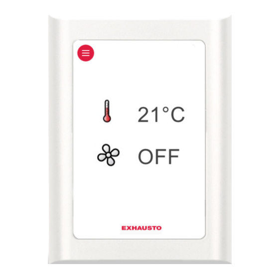
User mode 3006349-2022-04-05 2. User mode 2.1 Operation 2.1.1 Use of control icons in the menus HMI - Human Machine Interface panel Control icon Used for... Menu icon Navigation arrows up and down as well as setting val- ues. Approve icon for selection. Undo icon. -
Page 7: Overview Of Hmi Icons
User mode 3006349-2022-04-05 2.2 Overview of HMI icons Icon Description Manual operation Timer overridden until next changeover in the timer schedule Timer, current indoor air quality level is comfort Timer, current indoor air quality level is economy Timer, current indoor air quality level is standby Timer, VEX/CX has stopped Timer, no changeover times defined in timer schedule BMS-controlled operation... - Page 8 User mode 3006349-2022-04-05 Icon Description External start/stop disconnected. See Electrical Installation Guide for further information Summertime Wintertime No communication on the external BUS, or communication between the VEX/CX and HMI is disconnected Fire alarm. Closed circuit open and the pre-set fire alarm function acti- vated Fire! Startup: Web server accessing database.
-
Page 9: Technician And Service Levels
0000 When the whole number code has been selected, approve with ● The code for technician mode is1111 (some menus are hid- den or read-only). EXHAUSTO recommends this mode be used for normal service tasks Password ● The code for the specialist lev-... -
Page 10: Menu 3.2 - Selecting Language
Technician and service levels 3006349-2022-04-05 Step Action The display shows Main menu Press the up/down ar- Operating mode > row keys to find and select the de- Operating readings > sired function in the main menu. Settings > Alarm and info > Time and weekly plan >... -
Page 11: Menu 3.2.1 - Setting Date And Time
Technician and service levels 3006349-2022-04-05 Menu 3.2.1 - Setting date and time Step Action 3 Settings 3.2 General 3.2.1 Date and time Unit > Date and time > Date > 22-02-2009 General > Language > English Day > Wednesday Time > 13:11 Reset settings >... -
Page 12: Menu 3.6 - Web Server
Technician and service levels 3006349-2022-04-05 Menu 3.6 - Web server Contact the network administrator for information on the correct IP address, etc. If the admin password is lost, it can be reset to the factory setting. But note that this cannot be reversed. -
Page 13: Important When Servicing
Technician and service levels 3006349-2022-04-05 3.2 IMPORTANT when servicing Do not open the service doors before the supply voltage has been disconnec- ted at the isolation switch. The isolation switch is located on the left side of the connection box on top of the air handling unit. Weekly plan It is important to set ventilation to OFF when the weekly plan is active:... -
Page 14: Additional Service Hmi Panel
Technician and service levels 3006349-2022-04-05 If the VEX/CX is controlled via a BMS or Web server, BMS unit or Web these controls could override the OFF function and the server VEX/CX may start up irregularly. To disconnect the BMS or WEB server connection, you must remove the plug from the EXact2 main board. - Page 15 Technician and service levels 3006349-2022-04-05 Service panel con- nector - EXact2 Cable requirements The service panel cable can be ordered from EXHAUSTO (product number: HMI2SERVICEC). 15/108...
-
Page 16: Starting Up The Unit For Operation
Starting up the unit for operation 3006349-2022-04-05 4. Starting up the unit for operation The Modbus connectors must not be connected or removed while the units are powered up. Both Modbus units must be switched off before making changes, otherwise the units may be damaged. During commissioning, it may be necessary to work with the control system boxes open. -
Page 17: Start Configuration
Starting up the unit for operation 3006349-2022-04-05 Start configuration Step Action Check that the correct configuration for the VEX/CX has been selected at the factory via menu 3.3. Check that all accessories have been configured in menu If the CO sensor has been mounted, check in menu 3.1.2.1 "CO compensation", whether CO... -
Page 18: Menu 3.4 - Accessories
Starting up the unit for operation 3006349-2022-04-05 Menu 3.4 - Accessories 3.4 Accessories Line in menu 3.4 Factory-set and Remarks: Ice-detect. > Pressure De-icing method > should not be Heating coil > MHCE Cooling unit > None changed. Power step HCE > Filter detect. -
Page 19: Menu 3.4 Connecting Heating And Cooling Units
Starting up the unit for operation 3006349-2022-04-05 Line in menu 3.4 Factory-set and Remarks: should not be changed. Activating PIR sensor. Op- tions: ● Both (Both MIOPIR and PIRB connected) ● PIR2 (PIRB connected) ● PIR1 (MIOPIR connected) ● None When the sensor(s) is/are acti- vated by movement in the room, the VEX will be overrid-... -
Page 20: Menu 3.5 Bms
Starting up the unit for operation 3006349-2022-04-05 Heating coil - Cooling unit Menu 3.5 BMS Menu 3.5 - BMS 3.5 BMS Line in Menu 3.5 Remarks: BMS > None Configuration > Activating override control system BMS Op- tions: ● None ●... -
Page 21: Menu 1 - Selecting Operating Mode
HMI panel or the Web server Timer The unit is controlled automatically via a fixed weekly plan Note for commis- EXHAUSTO recommends that the operating mode be set to Manual during com- sioning missioning and changed to Timer operation when complete. 21/108... -
Page 22: Menu 3.1.1 - Operating Settings - Air Regulation
Starting up the unit for operation 3006349-2022-04-05 Note for manual When the unit is operating in Manual indoor climate level, the values set for the temperature setpoint (Temp. setpoint) and Air setpoint are shown immediately in the user menu. 3.1.1.1.4 Manual Air setpoint >... - Page 23 Starting up the unit for operation 3006349-2022-04-05 Method Meth- Description The following parameters Menu are set (1-8) Manual con- Constant speed ● Balance 3.1.1 Operating settings trol IAQ. levels > Manual control of fan speed Temp. reg. > Supply air Air reg.
- Page 24 Starting up the unit for operation 3006349-2022-04-05 Method Meth- Description The following parameters Menu are set (1-8) Constant Constant pressure-regulated ● Supply airflow values 3.1.1.4 Constant pressure pressure reg- supply air with fixed extract for maximum and min- Supply air: ulation of air setting imum ventilation...
-
Page 25: Menu 3.1.1 - Operating Settings Balance
Starting up the unit for operation 3006349-2022-04-05 Menu 3.1.1 - Operating settings Balance Definition Balance is the required ratio between the supply and extract airflows. The balance can only be maintained within certain operating ranges, limited by factors such as: ●... -
Page 26: Menu 3.1.1.5 Regulators
Starting up the unit for operation 3006349-2022-04-05 Menu 3.1.1.5 Regulators 3.1.1.5 Regulators Room temperature > Supply air temp. > Supply airflow > Extract airflow > Supply pressure > Extract pressure > Heat retention > Kp and Ti settings should only be changed by persons trained in commissioning ventilation systems. -
Page 27: Menu 3.1.1.1.X - Absolute/Relative Temperature
Starting up the unit for operation 3006349-2022-04-05 Menu 3.1.1.1.x - Absolute/Relative temperature Definition Used to select supply air or room temperature in relation to either absolute or rela- tive temperature. Absolute - Specify start temperature for heating coil or cooling unit. Relative - Permitted temperature changes relative to the heating coil or cooling unit start temperature. -
Page 28: Menu 3.1.1.1.X - Cooling Absolute Start
Starting up the unit for operation 3006349-2022-04-05 Example If the required room temperature is 21°C, and Heating Rel. start in the indoor air quality level menu is set to -3 K, the heating coil will begin to operate on a cold day when the temperature falls below 21°C - 3 K = 18°C. - Page 29 Starting up the unit for operation 3006349-2022-04-05 Limits, supply air temperature Max. and Min. may never be set closer to each other than 1K. If the following temperature will be is selected controlled by... supply air regula- supply air temperature Supply air temperature will never tion be higher than "Maximum"...
-
Page 30: Menu 3.1.1.1.X - Supply Air Regulation, Absolute
Starting up the unit for operation 3006349-2022-04-05 Max. and Min. may never be set closer to each other than 1K. the following will be adjusted..Supply air temp. maximum is The room temp. maximum is automatically re- set lower than the room duced to the same value as the supply air temp. -
Page 31: Menu 3.1.1.1.X - Room Temperature Regulation, Absolute
Starting up the unit for operation 3006349-2022-04-05 Menu 3.1.1.1.x - Room temperature regulation, absolute 3.1.1.1.x xxxxxxx Air setpoint > Air setpoint,cool °c Temp. setpoint > 21,0 Abs. / Rel. > Absolute Cool rel. start > °c Cool abs. start > 26,0 Heat rel. -
Page 32: Menu 3.1.1.1.X - Supply Air Regulation, Relative
Starting up the unit for operation 3006349-2022-04-05 Menu 3.1.1.1.x - Supply air regulation, relative 3.1.1.1.x xxxxxxx Air setpoint > Air setpoint,cool > Temp. setpoint > 21,0 °c Abs. / Rel. > Relativ Cool rel. start > Cool abs. start > Heat rel. - Page 33 Starting up the unit for operation 3006349-2022-04-05 Example 2: Minimum and Maximum supply air temp. limit Cooling rel. start and Heating rel. start: 33/108...
-
Page 34: Menu 3.1.1.1.X - Room Temperature Regulation, Relative
Starting up the unit for operation 3006349-2022-04-05 Menu 3.1.1.1.x - Room temperature regulation, relative 3.1.1.1.x xxxxxxx Air setpoint > Air setpoint,cool > Temp. setpoint > 21,0 °c Abs. / Rel. > Relativ Cool rel. start > Cool abs. start > Heat rel. -
Page 35: Menu 3.1.1 - Operation Settings - Temperature Regulation
Starting up the unit for operation 3006349-2022-04-05 Example 2: Minimum and Maximum room temp. limit Cooling rel. start and Heating rel. start: Menu 3.1.1 - Operation settings - Temperature regulation Select one of two temperature regulation methods: ● Supply air temperature regulation ●... -
Page 36: Compensation
Starting up the unit for operation 3006349-2022-04-05 ● Modulating heating coil(s). ● Modulating rotor speed ● Any external cooling unit and cooling recovery Select Select one of the following: ● Supply air regulation - Typically used when the unit serves several rooms with different loads (sunlight, people, machines). -
Page 37: Menu 3.1.2.1 - Co2 Compensation
Starting up the unit for operation 3006349-2022-04-05 Note ● All compensation options can be connected and active at the same time, and may influence the control airflow ● CO and humidity compensation cannot be activated if air regulation method 8 is selected. Autostart with timer If the weekly schedule is at OFF and either the CO or the humidity level exceeds... -
Page 38: Menu 3.1.2.2 - Humidity Compensation Of Airflow
Starting up the unit for operation 3006349-2022-04-05 Menu 3.1.2.2 - Humidity compensation of airflow Requirements A humidity sensor (RHB, MIO-RH, BMS) must be fitted in order to be able to se- lect humidity compensation of the airflow. The sensor must be installed in the room in which you wish to make compensation, such as a bathroom. -
Page 39: Menu 3.1.2.4 - Outdoor Compensation Of Airflow
Starting up the unit for operation 3006349-2022-04-05 Example Supply air temperature is... Airflow... Lower than Minimum Equivalent to Minimum (or lowest) airflow Between Minimum and Start increases gradually between mini- mum airflow and the set airflow Greater than Start Equivalent to set airflow ●... -
Page 40: Menu 3.1.3 - Temperature Compensation
Starting up the unit for operation 3006349-2022-04-05 Outdoor air temperature is Airflow... Lower than Minimum Equivalent to Minimum airflow Between Minimum and Start increases gradually between mini- mum airflow and the set airflow Greater than Start Equivalent to set airflow Menu 3.1.3 - Temperature compensation Menu 3.1.3.1 - Outdoor air temperature compensation Function... -
Page 41: Menu 3.1.3.2 - Summertime Compensation
Starting up the unit for operation 3006349-2022-04-05 Menu 3.1.3.2 - Summertime compensation Function The room temperature can be raised if outdoor air temperatures are high. Summertime compensation is active only if room temperature regulation is activa- ted for the indoor air quality level in Menu 3.1.1 (Operation settings -> Temp. reg. - >... -
Page 42: Menu 3.1.5 - Night-Time Cooling
Starting up the unit for operation 3006349-2022-04-05 Current pressure The current pressure drop across the outdoor air and extract air filters is dis- played. Warning Set the supply air and extract air soiled-filter warning level here. Alarm Set the outdoor air and extract air replace-filter alarm level here. Menu 8.1 The same settings that can be configured in Menu 3.1.4 can be configured here. - Page 43 Starting up the unit for operation 3006349-2022-04-05 3.1.5 Night-time cooling 3.1.5.9 Permit night-time cooling Active period > Summer Comfort > Set point > 18°C Standby > Min. supply temp. > 10°C Economy > ΔT max. > ΔT min. > Start time > 00:00 Stop time >...
-
Page 44: Menu 3.1.6 - Cold Recovery
Starting up the unit for operation 3006349-2022-04-05 *The extract air temperature is always used, regardless of whether a room tempera- ture sensor is installed for the system. Menu 3.1.5.9 - Per- mit night-time cool- is set to and the indoor air quality is activated level is Comfort/Standby/... -
Page 45: Room Temperature Limits
Starting up the unit for operation 3006349-2022-04-05 Supply air tempera- ture limits Setting Go to menu Lowest permitted supply air tempera- 3.1.8 Range: 10.0℃.. ture 0.250.0℃ Highest permitted supply air tempera- Range: 30.0℃.. ture 0.40.0°C The settings above must only be changed if special circumstances require it. -
Page 46: Menu 5 - Time And Weekly Plan
Starting up the unit for operation 3006349-2022-04-05 Menu 5 - Time and weekly plan Menu 5.1 - Date and time This menu is used to set the current date, day and time. Menu 5.2 - Weekly plan Plan type When "Timer" operation has been selected in Menu 1, the weekly plan must be configured. -
Page 47: Menu 7 - Safety Functions
Starting up the unit for operation 3006349-2022-04-05 Program example 5.2.2.1 Weekday 1 IAQ. level > Standby 1 Time of day > 06:00 2 IAQ. level > Comfort 2 Time of day > 07:30 3 IAQ. level > Economy 3 Time of day > 17:30 4 IAQ. -
Page 48: Menu 7.2 - Frost Protection Of Hcw
Starting up the unit for operation 3006349-2022-04-05 The inputs allow the connection of: ● Smoke detectors ● Fire thermostats (e.g. BT40, BT70 or BT70) ● BMS ● Fire control system If an input is not used, a jumper must be used (see Electrical Installation Guide) Menu 7.2 - Frost protection of HCW Setting of frost pro- tection... - Page 49 Starting up the unit for operation 3006349-2022-04-05 Stop temperature If the return water tem- and total Then perature does the fol- number of lowing within a five-mi- restarts nute period Rises above the constant > 0 Airflow is increased again to the nor- heating temperature mal operating level Remains below the con-...
-
Page 50: Operation
Operation 3006349-2022-04-05 5. Operation Menu 2 - Operating readings In general All of the operating parameters can be read in Menu 2. _ _ _ is shown in the menu if a given unit is not fitted. Menu 2.1 - Air temperatures 2 Operating readings 2.1 Air temperature 2.1.1 Setp. -
Page 51: Menu 2.1.1 - Set Points For Regulators
Operation 3006349-2022-04-05 Example VEX200 + Chiller Diagrams See appendix 1 for VEX200 diagrams. Menu 2.1.1 - Set points for regulators This menu shows set points for: 2.1.1 Setp. regulators ● The room temperature regulator Room 10,0 Heat recovery ● The heat recovery regulator 10,0 Cooling unit 10,0... -
Page 52: Menu 2.4 - Temperature Regulating Units
Operation 3006349-2022-04-05 Menu 2.4 - Temperature regulating units The menu shows the current: 2.4 Temp. reg. units ● heat recovery Heat recovery Heating coil ● output of heating coil (if installed) Heat pump unit Cooling unit ● output of heat pump unit (if installed) Cooling recovery ●... -
Page 53: Menu 2.7 - Ch Cooling Unit
Operation 3006349-2022-04-05 Menu 2.7 - CH cooling unit The menu shows: 2.7 Cooling/heat pump unit ● pressure gas pressure Comp. gas press. 0.00 Suc. gas press. 0.00 ● suction gas pressure Comp. gas press. 0.00 °c Feed temp. 0.00 °c ●... -
Page 54: Menu 2.12 - Hour Meters
Operation 3006349-2022-04-05 Menu 2.12 - Hour meters The menu shows the hour meters for fan motors and rotor motor. 2.11 Timers Supply air motor 266hr Extract air motor 1256hr Rotor 214hr Menu 2.13 - CO2/RH sensors (if mounted) The menu shows: 2.12 CO2/RH sensors ●... -
Page 55: Menu 8 - Service
Operation 3006349-2022-04-05 Menu 8 - Service Do not open the service doors before the supply voltage has been disconnec- ted at the isolation switch. The isolation switch is located on the left side of the connection box on top of the air handling unit. Weekly plan It is important to set ventilation to OFF when the weekly plan is active:... -
Page 56: Additional Service Hmi Panel
Operation 3006349-2022-04-05 If the VEX/CX is controlled via a BMS or Web server, BMS unit or Web these controls could override the OFF function and the server VEX/CX may start up irregularly. To disconnect the BMS or WEB server connection, you must remove the plug from the EXact2 main board. - Page 57 Operation 3006349-2022-04-05 Service panel con- nector - EXact2 Cable requirements The service panel cable can be ordered from EXHAUSTO (product number: HMI2SERVICEC). 57/108...
-
Page 58: Menu 8.2 - Vdi 6022
Operation 3006349-2022-04-05 Menu 8.2 - VDI 6022 VDI 6022 is a German hygiene standard. Menu 8.2 VDI 6022 Light > Filter pressure: Extract air filter Outdoor filter Lighting Switch light on/off (applies only to units ordered with lights. The light in the VEX switches off again when the menu is exited. -
Page 59: Menu 8.3.3 Heating Unit
Operation 3006349-2022-04-05 Rotation control If the rotor is not running: check ● Turn the rotor one revolution by hand. The value shown for rotation control should change each time rotation control is activated Menu 8.3.3 Heating unit For electric heating coil HCE: 8.3.3 Heating unit If there are no current faults for the heating coil ("Fault on unit"... -
Page 60: Menu 8.4 - Calibrating Mpt
Operation 3006349-2022-04-05 Menu 8.4 - Calibrating MPT The pressure transducers (MPT) may only be calibrated when the unit is stopped. The doors should be opened to equalise pressure with the surroundings and to ensure correct calibration. ● Select "Yes" for calibration (automatically changes to "No" again when the MPTs have been calibrated). -
Page 61: Alarms
Alarms 3006349-2022-04-05 6. Alarms 6.1 Alarms and info (Menu 4) Alarms shown in In the event of alarms/warnings on the system, one of the following icons is shown display in the menu bar’s right-hand corner in the user menu Alarms are shown in the event of unit faults or irregular operation ●... -
Page 62: Alarm Display And Current List - Cause Of Error
Alarms 3006349-2022-04-05 6.3 Alarm display and Current list – cause of error Current list 4.5 Current list Alarm 01 01144 2009-02-10 10:54:17 Alarm 02 02144 2009-02-10 11:01:12 Alarm 03 03073 2009-02-10 18:22:50 Alarm 04 12012 2009-02-10 18:25:00 Alarm 05 13071 2009-02-10 19:00:00 Alarm code... -
Page 63: List Of Alarms
Alarms 3006349-2022-04-05 A letter is shown following the alarm or info code: C = Clear S = Set The alarm log list shows the latest 100 alarms, warnings and past information. The first alarm/info to be added to the queue will be the first to be removed, if there are more than 100 of them (FIFO principle). - Page 64 Alarms 3006349-2022-04-05 Frequency converter 1 Troubleshooting Alarm description (See appendix 1: "Simplified diagrams" for the location of dampers, sen- sors, air directions, etc.) xx yy 01 01 One or more phases ● Check the cable between frequency converter 1 and motor between frequency converter and motor is/are short-circuited to...
- Page 65 Alarms 3006349-2022-04-05 Frequency converter 1 Troubleshooting Alarm description (See appendix 1: "Simplified diagrams" for the location of dampers, sen- sors, air directions, etc.) xx yy 01 15 Frequency converter Fault on frequency converter 1 hardware fault 01 16 Frequency converter ●...
- Page 66 Alarms 3006349-2022-04-05 Frequency converter 1 Troubleshooting Alarm description (See appendix 1: "Simplified diagrams" for the location of dampers, sen- sors, air directions, etc.) xx yy 02 01 One or more phases ● Check the cable between frequency converter 2 and motor between frequency converter and motor is/are short-circuited to...
- Page 67 Alarms 3006349-2022-04-05 Frequency converter 1 Troubleshooting Alarm description (See appendix 1: "Simplified diagrams" for the location of dampers, sen- sors, air directions, etc.) xx yy 02 15 Frequency converter Fault on frequency converter 2. hardware fault 02 16 Frequency converter ●...
- Page 68 Alarms 3006349-2022-04-05 Pressure transmitter 1 Troubleshooting Alarm description (See appendix 1: "Simplified diagrams" for the location of dampers, sen- sors, air directions, etc.) xx yy 04 01 No modbus communi- ● Check the modbus cable between the connection board (EX- cation to pressure act)/main board (EXact2) and MPT1.
- Page 69 Alarms 3006349-2022-04-05 Pressure transmitter 3 Troubleshooting Alarm description (See appendix 1: "Simplified diagrams" for the location of dampers, sen- sors, air directions, etc.) xx yy 06 01 No modbus communi- ● Check the modbus cable between the connection board (EX- cation to pressure act)/main board (EXact2) and MPT3.
- Page 70 Alarms 3006349-2022-04-05 Pressure transmitter 5 Troubleshooting Alarm description (See appendix 1: "Simplified diagrams" for the location of dampers, sen- sors, air directions, etc.) xx yy 08 01 No modbus communi- ● Check the modbus cable between the connection board (EX- cation to pressure act)/main board (EXact2) and MPT5.
- Page 71 Alarms 3006349-2022-04-05 Pressure transmitter 7 Troubleshooting Alarm description (See appendix 1: "Simplified diagrams" for the location of dampers, sen- sors, air directions, etc.) xx yy 10 01 No modbus communi- ● Check the cable between the connection board and MPT7 cation to pressure ●...
- Page 72 Alarms 3006349-2022-04-05 Temperature sensor Troubleshooting Alarm description (See appendix 1: "Simplified diagrams" for the location of dampers, sen- sors, air directions, etc.) xx yy TE11: TE11: ● Check the sensor's resistance complies with the actual tem- Extract air duct temper- perature.
- Page 73 Alarms 3006349-2022-04-05 Temperature sensor Troubleshooting Alarm description (See appendix 1: "Simplified diagrams" for the location of dampers, sen- sors, air directions, etc.) xx yy TE-RPT: TE-RPT: ● Check the sensor's resistance complies with the actual tem- Return water pipe tem- perature.
- Page 74 Alarms 3006349-2022-04-05 Fire thermostats Troubleshooting Alarm description (See appendix 1: "Simplified diagrams" for the location of dampers, sen- sors, air directions, etc.) xx yy 12 01 BT40/50, FIRE: BT40/50, FIRE: In event of Fire: Follow the building emergency Triggered fire alarm procedure has stopped VEX/CX Fire thermostat triggered when there is no fire:...
- Page 75 Alarms 3006349-2022-04-05 HC Alarm Troubleshooting Alarm description (See appendix 1: "Simplified diagrams" for the location of dampers, sen- sors, air directions, etc.) xx yy 14 01 Thermal fuse TSA70 HCE: activated Info is reset when the temperature falls below 70℃ 14 02 Thermal fuse TSA70 HCE:...
- Page 76 Alarms 3006349-2022-04-05 HC Alarm Troubleshooting Alarm description (See appendix 1: "Simplified diagrams" for the location of dampers, sen- sors, air directions, etc.) xx yy 14 10 Return water temp. too HCW: low. Frost protection ● Check that the hot water supply to the heating coil is function- activated.
- Page 77 Alarms 3006349-2022-04-05 HC Alarm Troubleshooting Alarm description (See appendix 1: "Simplified diagrams" for the location of dampers, sen- sors, air directions, etc.) xx yy 14 14 Could not increase re- HCW: turn water temp. within ● Check that the hot water supply to the heating coil is function- five minutes after frost ing.
- Page 78 Alarms 3006349-2022-04-05 HC Sensor Troubleshooting Alarm description (See appendix 1: "Simplified diagrams" for the location of dampers, sen- sors, air directions, etc.) xx yy 15 01 Supply air duct temper- ● Check the sensor's resistance complies with the actual tem- ature sensor discon- perature.
- Page 79 Alarms 3006349-2022-04-05 HC Controller Troubleshooting Alarm description (See appendix 1: "Simplified diagrams" for the location of dampers, sen- sors, air directions, etc.) xx yy 16 01 MHCW: Module config- Check the jumper in the CN6 connector on the heat control circuit ured incorrectly.
- Page 80 Alarms 3006349-2022-04-05 Airflow/pressure Troubleshooting Alarm description (See appendix 1: "Simplified diagrams" for the location of dampers, sen- sors, air directions, etc.) xx yy 20 01 Airflow/pressure in ex- The unit provides airflow that is 25% above the setpoint. tract air duct airflow too ●...
- Page 81 Alarms 3006349-2022-04-05 Airflow/pressure Troubleshooting Alarm description (See appendix 1: "Simplified diagrams" for the location of dampers, sen- sors, air directions, etc.) xx yy 20 12 Cooling cannot be re- The required air balance between supply air and extract air is still leased because sup- higher than the permitted limit of 1.15:1 after 30 minutes.
- Page 82 Alarms 3006349-2022-04-05 Temperature sensor MIO-TS Troubleshooting Alarm description (See appendix 1: "Simplified diagrams" for the location of dampers, sen- sors, air directions, etc.) xx yy 22 01 No modbus communi- ● Check the modbus cable between the connection board (EX- cation to MIO-TS mod- act)/main board (EXact2) and MIO module.
- Page 83 Alarms 3006349-2022-04-05 Motion sensor PIR Troubleshooting Alarm description (See appendix 1: "Simplified diagrams" for the location of dampers, sen- sors, air directions, etc.) xx yy 24 01 No modbus communi- ● Check the modbus cable between the connection board (EX- cation to PIR module act)/main board (EXact2) and PIR module.
- Page 84 Alarms 3006349-2022-04-05 Cooling unit Troubleshooting Alarm description (See appendix 1: "Simplified diagrams" for the location of dampers, sen- sors, air directions, etc.) xx yy 25 01 Cooling unit stopped ● Check the low-pressure switch. The low-pressure switch cuts because of low evapo- out at 0.69 bar and re-engages at 2.21 bar.
- Page 85 Alarms 3006349-2022-04-05 Cooling unit Troubleshooting Alarm description (See appendix 1: "Simplified diagrams" for the location of dampers, sen- sors, air directions, etc.) xx yy 25 08 Outdoor air duct tem- ● Check the sensor's resistance complies with the actual tem- perature sensor short- perature.
- Page 86 Alarms 3006349-2022-04-05 External cooling unit (MXCU) control Troubleshooting Alarm description (See appendix 1: "Simplified diagrams" for the location of dampers, sen- sors, air directions, etc.) xx yy 28 01 Module configured in- ● Check jumper in CN6 connector on cooling control circuit correctly.
- Page 87 Alarms 3006349-2022-04-05 MCCW Troubleshooting Alarm description (See appendix 1: "Simplified diagrams" for the location of dampers, sen- sors, air directions, etc.) xx yy 30 01 Supply air duct temper- ● Check the sensor's resistance complies with the actual tem- ature sensor discon- perature.
- Page 88 Modbus Status Troubleshooting Alarm description (See appendix 1: "Simplified diagrams" for the location of dampers, sen- sors, air directions, etc.) xx yy 34 01 SendModbusDataRe- Contact EXHAUSTO A/S ceive fail 34 02 SendModbusDataSend Contact EXHAUSTO A/S fail 34 03 SendModbusDataCon-...
- Page 89 Alarms 3006349-2022-04-05 External control Troubleshooting Alarm description (See appendix 1: "Simplified diagrams" for the location of dampers, sen- sors, air directions, etc.) xx yy 35 01 No modbus communi- ● Check the modbus cable between the connection board (EX- cation to the MIO- act)/main board (EXact2) and MIO module.
- Page 90 Alarms 3006349-2022-04-05 EC Controller 1 Troubleshooting Alarm description (See appendix 1: "Simplified diagrams" for the location of dampers, sen- sors, air directions, etc.) xx yy 36 02 The supply voltage to ● Check for low voltage to EC controller 1 the EC controller is too 36 03 The supply voltage to...
- Page 91 Alarms 3006349-2022-04-05 EC Controller 2 Troubleshooting Alarm description (See appendix 1: "Simplified diagrams" for the location of dampers, sen- sors, air directions, etc.) xx yy 37 02 The supply voltage to ● Check for low voltage to EC controller 2 the EC controller is too 37 03 The supply voltage to...
- Page 92 Alarms 3006349-2022-04-05 Configuration Troubleshooting Alarm description (See appendix 1: "Simplified diagrams" for the location of dampers, sen- sors, air directions, etc.) xx yy 40 01 Type has not been ● Configure the VEX/CX in menu 3.3 configured 40 02 VEX size has not been ●...
- Page 93 43 07 Suction gas pressure ● Check connection between sensor and cooling control, sensor has short- ● Contact EXHAUSTO service. circuited. 43 08 Suction gas pressure ● Check connection between sensor and cooling control, sensor has been inter- ●...
- Page 94 ● Disconnect the supply voltage to the cooling unit for 1 minute via the isolation switch on the cooling unit. ● Then cancel the alarm via the HMI panel. 43 15 Unknown configura- Chiller size has not been configured. Contact EXHAUSTO service. tion. Cooling status Troubleshooting Alarm description (See appendix 1: "Simplified diagrams"...
- Page 95 Alarms 3006349-2022-04-05 MXHP Troubleshooting Alarm description (See appendix 1: "Simplified diagrams" for the location of dampers, sen- sors, air directions, etc.) xx yy 45 01 Supply air duct temper- ● Check the sensor's resistance complies with the actual tem- ature sensor discon- perature.
- Page 96 Alarms 3006349-2022-04-05 MCOCW Alarm Troubleshooting Alarm description (See appendix 1: "Simplified diagrams" for the location of dampers, sen- sors, air directions, etc.) xx yy 47 05 External pump or DX A general alarm has been received from the external pump or DX unit has an active unit.
- Page 97 Alarms 3006349-2022-04-05 MCOCW Alarm Troubleshooting Alarm description (See appendix 1: "Simplified diagrams" for the location of dampers, sen- sors, air directions, etc.) xx yy 47 12 Return water temp. HCW: measured by external ● Check that the hot water supply to the heating coil is function- sensor becoming too ing.
- Page 98 Alarms 3006349-2022-04-05 MCOCW Sensor Troubleshooting Alarm description (See appendix 1: "Simplified diagrams" for the location of dampers, sen- sors, air directions, etc.) xx yy 48 01 Supply air duct temper- ● Check the sensor's resistance complies with the actual tem- ature sensor discon- perature.
- Page 99 Alarms 3006349-2022-04-05 MCOCW Control Troubleshooting Alarm description (See appendix 1: "Simplified diagrams" for the location of dampers, sen- sors, air directions, etc.) xx yy 49 01 Module configured in- ● Check the jumper in the CN6 connector on the MCOCW mod- correctly.
- Page 100 Alarms 3006349-2022-04-05 ALC extract air damper alarm Troubleshooting Alarm description (See appendix 1: "Simplified diagrams" for the location of dampers, sen- sors, air directions, etc.) xx yy 52 01 MD1: No communica- ● Check Modbus cable to and from ALC damper for faulty tion to damper motor.
-
Page 101: Appendix 1 - Simplified Diagrams Simplified Diagrams
Appendix 1 - Simplified diagrams 3006349-2022-04-05 Appendix 1 - Simplified diagrams Simplified diagrams Simplified diagrams for unit with chiller For units with an installed chiller, see the simplified diagrams at the rear of the chiller instructions. VEX240-250-260-270L fan placement 1 TE22 MPT2 T-Cool... -
Page 102: Vex240-250-260-270L Fan Placement 2
Appendix 1 - Simplified diagrams 3006349-2022-04-05 VEX240-250-260-270L fan placement 2 MPT1 TE11 TE12 1,1,A 1,2,A Extract air Exhaust air 2,2,A 2,1,A Supply air Outdoor air TE21 T-Cool T-heat TE22 RHX2M MPT2 VEX240-250-260-270L fan placement 2 MPT1 T-heat TE22 T-Cool TE21 2,2,A 2,1,A Outdoor air... -
Page 103: Appendix 2 - Temperature Resistance Table
Appendix 2 - Temperature resistance ta- 3006349-2022-04-05 Appendix 2 - Temperature resistance table Temperature resistance table DC95 Temperature Resistance Temperature Resistance Temperature Resistance [°C] [Ohm] [°C] [Ohm] [°C] [Ohm] 324270 34464 5774 320139 32737 5545 299580 31107 5326 280471 29567 5116 262702 28113... - Page 104 Appendix 2 - Temperature resistance ta- 3006349-2022-04-05 Temperature Resistance Temperature Resistance Temperature Resistance [°C] [Ohm] [°C] [Ohm] [°C] [Ohm] 1390 840.6 528.5 1346 815.7 514.0 1303 791.6 500.0 1261 768.4 486.4 1221 746.0 473.2 1183 724.3 460.5 1146 703.3 448.2 1110 683.1 436.3...
- Page 105 3006349-2022-04-05 105/108...
- Page 106 3006349-2022-04-05 106/108...
- Page 107 3006349-2022-04-05 107/108...
Need help?
Do you have a question about the EXact2 HMI2-350-TOUCH and is the answer not in the manual?
Questions and answers