Advertisement
Quick Links
3005879-2018-05-31
Electrical installation guide
for VEX240HX/250HX with third-party control system
Electrical installation........................................ Chapter 1 + 2
EXHAUSTO A/S
Odensevej 76
DK-5550 Langeskov
Tel. +45 65 66 12 34
Fax +45 65 66 11 10
exhausto@exhausto.dk
www.exhausto.dk
VEX240-250HX
Original instructions
Advertisement

Related Manuals for Exhausto VEX240HX


Summary of Contents for Exhausto VEX240HX
- Page 1 VEX240-250HX 3005879-2018-05-31 Electrical installation guide for VEX240HX/250HX with third-party control system Electrical installation........Chapter 1 + 2 Original instructions EXHAUSTO A/S Tel. +45 65 66 12 34 Odensevej 76 Fax +45 65 66 11 10 DK-5550 Langeskov exhausto@exhausto.dk www.exhausto.dk...
-
Page 2: Table Of Contents
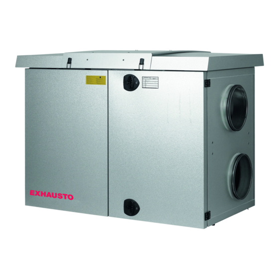
3005879-2018-05-31 1. Voltage supply diagram 1.1. Connection diagram for VEX with motor control (MC)........4 1.1.1. Alarm relay function..................7 2. Installation of the VEX 2.1. Scope of installation....................8 2.2. Selection of rotor direction of rotation..............8 2.3. Control of step motor.................... 9 2/12... - Page 3 ● Or use a padlock. Use the han- dle’s built-in padlock fixture. Padlock fitting Rating plate The VEX unit rating plate shows: ● VEX unit, type (1) ● production number (2) Always have the production number ready when contacting EXHAUSTO A/S. 3/12...
-
Page 4: Voltage Supply Diagram
Voltage supply diagram 3005879-2018-05-31 1. Voltage supply diagram 1.1 Connection diagram for VEX with motor control (MC) VEX240 - 1 x 230 V The diagram below illustrates connection of the supply voltage to the motor con- trol and rotor. *) To adjust the rotor speed, see section "Control of step motor". 4/12... - Page 5 Voltage supply diagram 3005879-2018-05-31 VEX250 - 3 x 400 V The diagram below illustrates connection of the supply voltage to the motor con- trol and rotor. *) To adjust the rotor speed, see section "Control of step motor". Explanation of dia- grams Designation Explanation...
- Page 6 Voltage supply diagram 3005879-2018-05-31 Electrical data The table below shows max. phase current and max. neutral current Type Supply voltage Max. Max. DRHX phase neutral phase phase current current cur- cur- (total) (Rated rent rent current) VEX240 1 x 230V+N+PE VEX250 3 x 400V+N+PE 12.5...
-
Page 7: Alarm Relay Function
Voltage supply diagram 3005879-2018-05-31 1.1.1 Alarm relay function Description Drawing The diagram shows which two terminals from MC and RHX2M are connec- ted to the terminal block in the connection box MC: terminal 9-10 and terminal 15-16 The alarm relay position in the case of power failure or similar The alarm relay position in... -
Page 8: Installation Of The Vex
Installation of the VEX 3005879-2018-05-31 2. Installation of the VEX 2.1 Scope of installation VEX unit The electrical installation for the VEX unit comprises the following tasks: Connection box Wiring configurations for the terminal board in the connection box: ● Supply voltage for motor controls 1 and 2 ●... -
Page 9: Control Of Step Motor
Installation of the VEX 3005879-2018-05-31 Selecting Left/Right To change the VEX from, e.g., Left to Right, 2 of the 3 motor cables to the rotor motor must be switched. Step Action Open the doors – the rotor control is located at the bottom of the VEX. - Page 10 Installation of the VEX 3005879-2018-05-31 The table below shows the maximum permitted step motor rotational speed – de- pendent on the size of the VEX. If the rotational speed exceeds the given value, the motor will become overloaded and shut down. Max.
- Page 11 3005879-2018-05-31 11/12...
Need help?
Do you have a question about the VEX240HX and is the answer not in the manual?
Questions and answers