Advertisement
Quick Links
Advertisement

Related Manuals for AeroWorks STINGRAY


Summary of Contents for AeroWorks STINGRAY
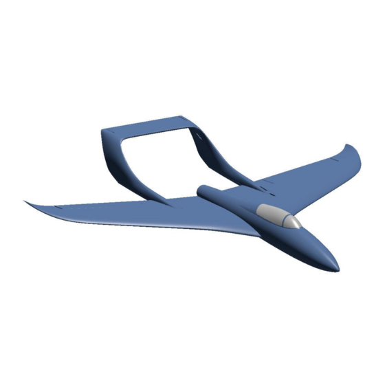
- Page 1 ASSEMBLY MANUAL AND USER GUIDE STINGRAY By 3D AEROWORKS...
- Page 2 This model has taken many hours of hard work and testing in order to provide a nice flying aircraft. Please do not share it. Please show your appreciation by directing interested parties to the link below. https://cults3d.com/en/3d-model/various/stingray-800mm-pusher GENERAL SPECIFICATIONS WINGSPAN:...
- Page 5 REQUIRED TOOLS: KNIFE LIGHTER SANDPAPER (MEDIUM GRIT 320 recommended) PLIERS CA GLUE SCREW DRIVERS FILE OR RASP REQUIRED COMPONENTS: X1 2826 2200KV MOTOR (or similar) X1 30AMP ESC X1 2200MAH 3S LIPO OR SIMILAR X2 9G SERVO BAMBOO SKEWERS 3MM X2 10mm X 10mm X 2mm MAGNET (ROUND) X4 16mm x 29mm HINGES VELCRO...
- Page 6 ASSEMBLY INSTRUCTIONS All faces which are to be glued to other parts need to be given a light sanding (scuff the surface) to assist with glue adhesion.
- Page 7 Check the fitment of all parts before gluing to make sure a good bond takes place. There should not be any gaps visible in the joins. Glue sections of the fuselage together using CA glue. (see images) Remove the servo tunnel access in the fuselage section. (highlighted red)
- Page 8 Cut two 10mm-15mm sections of food skewer. Insert into the “Boom 1” sections and glue the “boom 2” sections in place as shown. Do the same for connecting “Boom 3” to “Boom 2” as shown.
- Page 9 Fit the elevator to the horizontal stabiliser and connect the stabiliser to each side of the booms. IMPORTANT! Only 2 small drops of CA is needed for each slot for the hinges. Too much CA and the hinge will bind and be unusable. TIP: After adding the CA, use a tissue to wipe away the excess.
- Page 10 Fit small sections of 3mm skewer into the inner section of both wings. Align these tabs with the holes in the fuselage as the wings are glued to the fuselage. Cut four 35mm lengths of 3mm skewer and pin the tail boom to the aft section of the inner wings.
- Page 11 Glue the outer sections of the wings together using 10mm sections of 3mm skewer to align the parts. Glue the aileron in place, the control horn is to be on the underside of the wing.
- Page 12 Glue the outer and inner sections of the wings together. Glue sections of the canopy together using 3mm skewer. Fit the magnets into the canopy and fuselage. Fit the motor to the motor mount and connect to the esc. The motor mount is designed to be a relatively firm fit.
- Page 13 BALANCING AND CG Fit the battery using Velcro as required and balance the aircraft inverted on the CG marking points located 148mm aft of the leading edge at the wing root. It is advisable on the first flight for the aircraft to be balanced on the cg markings, then move forward or aft as desired.
- Page 14 PARTS LINKS: 2826 2200KV https://de.aliexpress.com/item/1005002196959683.html?spm=a2g0o.productlist.0.0.6865546 92gBgqu&algo_pvid=2a35bba8-713a-4d82-be03-7d09757fa32e&algo_expid=2a35bba8-713 a-4d82-be03-7d09757fa32e-0&btsid=2100bdf016211821631778504e2ed8&ws_ab_test=sea rchweb0_0,searchweb201602_,searchweb201603_ 30AMP ESC https://de.aliexpress.com/item/32905648461.html?spm=a2g0o.productlist.0.0.edb7519evyB8 Nr&algo_pvid=52adfa0e-b4fe-41e1-8092-1d356607a5ba&algo_expid=52adfa0e-b4fe-41e1-8 092-1d356607a5ba-0&btsid=2100bdf016211822080491111e2ed8&ws_ab_test=searchweb0 _0,searchweb201602_,searchweb201603_ 2200mah 3s LIPO https://de.aliexpress.com/item/32833411481.html?spm=a2g0o.productlist.0.0.64ef480aYCzl2 n&algo_pvid=f86fc7a0-0324-4584-9081-c8b4b1a543a2&algo_expid=f86fc7a0-0324-4584-90 81-c8b4b1a543a2-1&btsid=2100bdf016211822705142563e2ed8&ws_ab_test=searchweb0_ 0,searchweb201602_,searchweb201603_ 9g servo https://de.aliexpress.com/item/32898059654.html?spm=a2g0o.productlist.0.0.7d394771z9xf Zq&algo_pvid=26dd1d90-4d3b-4f94-955c-e26a127ba26c&algo_expid=26dd1d90-4d3b-4f94- 955c-e26a127ba26c-3&btsid=2100bdf016211823001362964e2ed8&ws_ab_test=searchweb 0_0,searchweb201602_,searchweb201603_ X2 BAMBOO FOOD SKEWERS (3mm diameter) HEAT SHRINK TUBE 3mm https://hobbyking.com/en_us/turnigy-3mm-heat-shrink-tube-black-1mtr-1.html?queryID=c16c 094bb26b18e39fabcb12a93a96cb&objectID=46911&indexName=hbk_live_magento_en_us_ products...
- Page 15 X4 10mm X 10mm X 2mm MAGNET (ROUND) https://www.aliexpress.com/item/1005001362617359.html?spm=a2g0o.productlist.0.0.5da36 07dAATh5j&algo_pvid=b9e32b8a-0d4f-469a-b838-b478442dda50&algo_expid=b9e32b8a-0 d4f-469a-b838-b478442dda50-0&btsid=0bb0623a15991797178681785e1811&ws_ab_test=s earchweb0_0,searchweb201602_,searchweb201603_ 16x29 HINGES https://de.aliexpress.com/item/32659926010.html?spm=a2g0o.productlist.0.0.5e7f7ef2zIc3q X&algo_pvid=478c4573-19ad-4939-ba11-475e3dc6139e&algo_expid=478c4573-19ad-4939- ba11-475e3dc6139e-0&btsid=2100bdf016211823370763498e2ed8&ws_ab_test=searchweb 0_0,searchweb201602_,searchweb201603_ VELCRO – (local hardware store) 10mm x 1000mm carbon tube https://de.aliexpress.com/item/4000390835692.html?spm=a2g0o.productlist.0.0.63ab4e77k W2VnK&algo_pvid=3877bd8c-0e1c-46e8-8888-d99e4a90ccd2&algo_expid=3877bd8c-0e1c- 46e8-8888-d99e4a90ccd2-2&btsid=2100bdf016211824187545230e2ed8&ws_ab_test=searc hweb0_0,searchweb201602_,searchweb201603_ m2 x10mm screws https://www.ebay.com.au/itm/400PCS-M2-M2-6-Pan-Head-Self-Tapping-Screws-Assorted-Kit -Stainless-Steel-Black/254399626404?hash=item3b3b663ca4:g:CLEAAOSwQLZdsqkd&frce ctupt=true Piano wire https://de.aliexpress.com/item/32975279180.html?spm=a2g0s.9042311.0.0.2e0f4c4d0HE2d...
- Page 16 Thank you for supporting us! We hope you enjoy many hours of flying your Stingray. If you have any questions regarding the build process or set-up of your model, please contact us at: Aeroworks3d@outlook.com...
Need help?
Do you have a question about the STINGRAY and is the answer not in the manual?
Questions and answers