Table of Contents
Advertisement
Quick Links
Installation Sheet (Wiegand Interface)
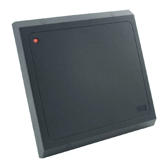
Sentinel-Prox MR-1824HiLo Reader
Reader Description
The Sentinel-Prox MR-1824HiLo Reader Set is a pair of medium-range radio-frequency proximity readers with
special programming that allows them to work as a set at a single installation site, without interference between
the two readers. The readers' firmware coordinates the duty cycles for the two readers. This prevents one
reader from transmitting its signal while the other reader is transmitting to, or receiving a reply from, an AWID
encoded credential. Reader labels and instructions are special. There is output on the Wiegand data lines only.
Parts List
(a) Installation sheet ......................................................... 1
(b) MR-1824 Reader ........................................................ 2
(c) #6-20 x 1.375" self-tapping screw .............................. 8
Installation Procedure for Each Reader
1. Position the first reader (item b in the Parts List) at the desired location.
requirements. Drill 4 holes for the screws or anchors, and drill 1 clearance hole for the cable (see Figure 1).
The installer determines the size of mounting holes and cable clearance hole.
2. Clip off the white inline connector from the end of the reader's cable. Keep the wires as long as possible.
3. Use a linear regulated DC power supply, between 5 volts (current rating 800 milliamperes or more)
and 12.0 volts maximum (current rating 2 amperes or more) for the combined readers. Do not power
the MR-1824HiLo from the reader port's DC voltage terminals on the panel – use a separate DC power
supply. (For guaranteed performance, AWID offers P/N PS-123.3A power module.) Tie the ground side
of all DC circuits together – including both MR-1824 readers, the panel's reader input port, the separate
DC power supply, and the door lock or gate motor contacts.
4. Connect the reader's wires for ground, data-0, data-1, LED and power, and the silver drain wire (see Fig. 2).
Connect the yellow wire only if used for Beeper control by the panel. Connect the orange and violet wires
to the opposite colors (violet and orange) on the other reader of the set. Do not connect the blue wire.
Tape or cap the unused wires separately. The MR-1824HiLo set uses a single Wiegand input on the panel.
5. To install the reader's cable through the wall directly behind the reader, insert both cable slot plugs
(item f in the Parts List) in the sides of the reader's top cover. To run the cable exiting from the side of the
reader, press the cable into the curved channel and guide the cable out of the desired side of the reader.
Then insert the cable slot plug in the other side of the top cover. Extend the cable straight away from
the reader housing as far as possible.
6. Install the reader on the mounting surface, using screws (item c in the Parts List) and anchors (item d)
as necessary.
7. Repeat steps 1 through 6 for the second reader of the MR-1824HiLo set. Readers may be up to 75 ft apart.
8. Apply DC power to both readers. The LED is steady amber. (The beeper does not sound.)
Present any AWID proximity credential (card, keytag or wafer) briefly to the reader. The beeper sounds a
9.
single Long beep. The LED is steady red to indicate Standby mode. The reader is now initialized and can
read cards. Note: All credentials must be AWID's products. Other companies' cards and tags will not read.
10. The LED color in Standby mode may be changed from red to green, or from green to red, using a
Color Changer card, available from AWID. Remove power from the reader for a few seconds, and then
restore power. While the LED is amber, present the Color Changer card to toggle the LED color at Standby.
When the LED color changes, remove the card.
11. When installation is complete and the readers have been tested, insert screw-hole plugs (item e in
the Parts List) into the screw clearance holes to conceal the screw heads. Note: Screw-hole plugs are
for one-time use. After they are seated, they cannot be removed without damaging the plugs.
MR-1824HiLo Installation Sheet
(d) Plastic anchor ............................................................. 8
(e) Screw-hole plug......................................... 10 (2 spare)
(f) Cable slot plug............................................................ 4
v. 1.3
Observe ADA height
Page 1 of 3
Advertisement
Table of Contents

Related Manuals for AWID Sentinel-Prox MR-1824HiLo


Summary of Contents for AWID Sentinel-Prox MR-1824HiLo
- Page 1 The readers’ firmware coordinates the duty cycles for the two readers. This prevents one reader from transmitting its signal while the other reader is transmitting to, or receiving a reply from, an AWID encoded credential. Reader labels and instructions are special. There is output on the Wiegand data lines only.
- Page 2 4. MR-1824HiLo readers have Wiegand-protocol electrical interface only. (There is no RS-232 interface.) 5. For additional information, please visit AWID’s Web site www.awid.com. For technical support questions, contact www.awid.com/support, or call 1-800-369-5533 in the U.S. or +1-408-825-1100 from 8:00 a.m. to 5:00 p.m. Pacific Time. Compliance FCC: This equipment has been tested and found to be in compliance with the limits for FCC part 15, Class A digital device.
- Page 3 FIGURE 1: Holes Location FIGURE 2: Wiring Diagram (Wiegand) MR-1824HiLo Installation Sheet v. 1.3 Page 3 of 3...
Need help?
Do you have a question about the Sentinel-Prox MR-1824HiLo and is the answer not in the manual?
Questions and answers