Advertisement
Installation Sheet (Wiegand Interface)
Installation Sheet (Wiegand Interface)
Installation Sheet (Wiegand Interface)
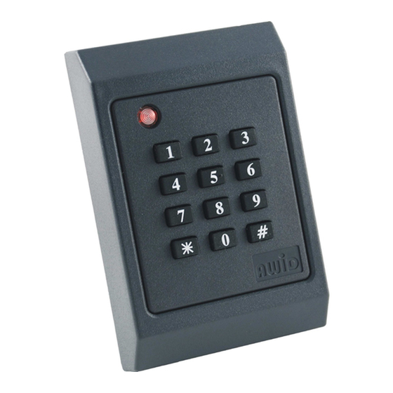
KP-6840 LF Card & PIN Reader
KP-6840 LF Card & PIN Reader
KP-6840 LF Card & PIN Reader
These instructions are for AWID's Model KP-6840 reader, using compatible proximity credentials from AWID.
These instructions are for AWID's Model KP-6840 reader, using compatible proximity credentials from AWID.
These instructions are for AWID's Model KP-6840 reader, using compatible proximity credentials from AWID.
Parts List
Parts List
Parts List
(a) 1 Installation Sheet for KP-6840
(a) 1 Installation Sheet for KP-6840
(a) 1 Installation Sheet for KP-6840
Preparation
Preparation
Preparation
Reader Location: Select the reader's mounting location. The KP-6840 Reader may be screwed to a single-gang
Reader Location: Select the reader's mounting location. The KP-6840 Reader may be screwed to a single-gang
Reader Location: Select the reader's mounting location. The KP-6840 Reader may be screwed to a single-gang
utility box like a cover plate, or to a wall or other surface. On a metal surface, read range is reduced about 20%.
utility box like a cover plate, or to a wall or other surface. On a metal surface, read range is reduced about 20%.
utility box like a cover plate, or to a wall or other surface. On a metal surface, read range is reduced about 20%.
The KP-6840 Reader may be installed indoors or outdoors, but needs protection from direct rain or snow.
The KP-6840 Reader may be installed indoors or outdoors, but needs protection from direct rain or snow.
The KP-6840 Reader may be installed indoors or outdoors, but needs protection from direct rain or snow.
DC Power Supply: DC power for this reader is usually supplied from the +DC and Ground terminals of the
DC Power Supply: DC power for this reader is usually supplied from the +DC and Ground terminals of the
DC Power Supply: DC power for this reader is usually supplied from the +DC and Ground terminals of the
Wiegand reader port on the system's panel. If this is not possible, use an independent power supply. Power may
Wiegand reader port on the system's panel. If this is not possible, use an independent power supply. Power may
Wiegand reader port on the system's panel. If this is not possible, use an independent power supply. Power may
be shared with other readers if the supply has sufficient current capacity. The power supply should be close to
be shared with other readers if the supply has sufficient current capacity. The power supply should be close to
be shared with other readers if the supply has sufficient current capacity. The power supply should be close to
+12 volts DC (as low as +5 volts is OK); 1 ampere capacity; linear-rated; regulated DC output.
+12 volts DC (as low as +5 volts is OK); 1 ampere capacity; linear-rated; regulated DC output.
+12 volts DC (as low as +5 volts is OK); 1 ampere capacity; linear-rated; regulated DC output.
Cable to Controller and Power Supply: 4 to 7 conductors from reader to the system (2 wires for DC power,
Cable to Controller and Power Supply: 4 to 7 conductors from reader to the system (2 wires for DC power,
Cable to Controller and Power Supply: 4 to 7 conductors from reader to the system (2 wires for DC power,
2 wires for Wiegand data, and 1 to 3 wires for external LED, Beeper/Alarm, and Hold control, if used).
2 wires for Wiegand data, and 1 to 3 wires for external LED, Beeper/Alarm, and Hold control, if used).
2 wires for Wiegand data, and 1 to 3 wires for external LED, Beeper/Alarm, and Hold control, if used).
22 gauge stranded wires. Overall 100% shield for both power and data. 500 feet maximum length.
22 gauge stranded wires. Overall 100% shield for both power and data. 500 feet maximum length.
22 gauge stranded wires. Overall 100% shield for both power and data. 500 feet maximum length.
If the DC power supply is separated from the panel's reader port, the reader's
If the DC power supply is separated from the panel's reader port, the reader's
If the DC power supply is separated from the panel's reader port, the reader's
connected to both the DC power supply's Negative terminal and the panel reader port's Ground terminal.
connected to both the DC power supply's Negative terminal and the panel reader port's Ground terminal.
connected to both the DC power supply's Negative terminal and the panel reader port's Ground terminal.
If the separate DC power supply is close to the reader, run two 22-gauge cables – 2 wires for DC power,
If the separate DC power supply is close to the reader, run two 22-gauge cables – 2 wires for DC power,
If the separate DC power supply is close to the reader, run two 22-gauge cables – 2 wires for DC power,
and 3 to 6 wires for Wiegand data (including Ground) and for the external control lines, if used.
and 3 to 6 wires for Wiegand data (including Ground) and for the external control lines, if used.
and 3 to 6 wires for Wiegand data (including Ground) and for the external control lines, if used.
Both cables must be overall-shielded and earth-grounded (at the end far from the reader).
Both cables must be overall-shielded and earth-grounded (at the end far from the reader).
Both cables must be overall-shielded and earth-grounded (at the end far from the reader).
Conduit: If cables are pulled through metal conduit, the conduit should be earth-grounded (like the cables).
Conduit: If cables are pulled through metal conduit, the conduit should be earth-grounded (like the cables).
Conduit: If cables are pulled through metal conduit, the conduit should be earth-grounded (like the cables).
Keypad Settings
Keypad Settings
Keypad Settings
The KP-6840 reader is shipped with the keypad's output programmed for buffered 26-bit output, and its facility
The KP-6840 reader is shipped with the keypad's output programmed for buffered 26-bit output, and its facility
The KP-6840 reader is shipped with the keypad's output programmed for buffered 26-bit output, and its facility
code (or site code) set at 000. These two settings can be changed at your shop before you go to the installation site.
code (or site code) set at 000. These two settings can be changed at your shop before you go to the installation site.
code (or site code) set at 000. These two settings can be changed at your shop before you go to the installation site.
Just connect DC power from a bench supply or from a 9 volt or 12 volt battery to the
Just connect DC power from a bench supply or from a 9 volt or 12 volt battery to the
Just connect DC power from a bench supply or from a 9 volt or 12 volt battery to the
Start either programming routine with DC removed from the KP-6840 unit. Keep the KP-6840 fully assembled.
Start either programming routine with DC removed from the KP-6840 unit. Keep the KP-6840 fully assembled.
Start either programming routine with DC removed from the KP-6840 unit. Keep the KP-6840 fully assembled.
Good keypad technique: Press key in straight for about ½ second. Separate the keystrokes -- one key at a time.
Good keypad technique: Press key in straight for about ½ second. Separate the keystrokes -- one key at a time.
Good keypad technique: Press key in straight for about ½ second. Separate the keystrokes -- one key at a time.
Keypad's Output Format
Keypad's Output Format
Keypad's Output Format
1. While the DC power is disconnected -- Press and hold the 4 key to change the format to 4-bit data burst;
1. While the DC power is disconnected -- Press and hold the 4 key to change the format to 4-bit data burst;
1. While the DC power is disconnected -- Press and hold the 4 key to change the format to 4-bit data burst;
or hold the 8 key to change the format to 8-bit data burst; or hold the 2 key to restore 26-bit buffered data.
or hold the 8 key to change the format to 8-bit data burst; or hold the 2 key to restore 26-bit buffered data.
or hold the 8 key to change the format to 8-bit data burst; or hold the 2 key to restore 26-bit buffered data.
2. With the 4 or 8 or 2 key still pressed in, connect the DC power. Within 3 seconds there is a beep
2. With the 4 or 8 or 2 key still pressed in, connect the DC power. Within 3 seconds there is a beep
2. With the 4 or 8 or 2 key still pressed in, connect the DC power. Within 3 seconds there is a beep
sequence, and the LED changes to standby-red.
sequence, and the LED changes to standby-red.
sequence, and the LED changes to standby-red.
3. Now release the pressed key. The change in keypad output format has been saved.
3. Now release the pressed key. The change in keypad output format has been saved.
3. Now release the pressed key. The change in keypad output format has been saved.
Facility Code in Keypad's 26-bit Buffered Output
Facility Code in Keypad's 26-bit Buffered Output
Facility Code in Keypad's 26-bit Buffered Output
1. Connect the DC power. Watch the unit's LED. While it is amber, slowly enter the 10-digit password
1. Connect the DC power. Watch the unit's LED. While it is amber, slowly enter the 10-digit password
1. Connect the DC power. Watch the unit's LED. While it is amber, slowly enter the 10-digit password
9 1 4 3 6 9 8 8 0 0; end with the # key. Press each key solidly. There is a short beep during each keystroke.
9 1 4 3 6 9 8 8 0 0; end with the # key. Press each key solidly. There is a short beep during each keystroke.
9 1 4 3 6 9 8 8 0 0; end with the # key. Press each key solidly. There is a short beep during each keystroke.
2. Within 3 seconds, start entering the facility code's 3 digits (between 001 and 255); end with the # key.
2. Within 3 seconds, start entering the facility code's 3 digits (between 001 and 255); end with the # key.
2. Within 3 seconds, start entering the facility code's 3 digits (between 001 and 255); end with the # key.
3. There is a long beep and the LED color changes to standby-red. The facility code has been saved.
3. There is a long beep and the LED color changes to standby-red. The facility code has been saved.
3. There is a long beep and the LED color changes to standby-red. The facility code has been saved.
KP-6840 Reader Installation Sheet
KP-6840 Reader Installation Sheet
KP-6840 Reader Installation Sheet
(b) 1 Model KP-6840 Reader/Keypad
(b) 1 Model KP-6840 Reader/Keypad
(b) 1 Model KP-6840 Reader/Keypad
(c) 2 #6-32 × 1" machine screw (for single-gang utility box)
(c) 2 #6-32 × 1" machine screw (for single-gang utility box)
(c) 2 #6-32 × 1" machine screw (for single-gang utility box)
Version 2.1 / Doc# 041508
Version 2.1 / Doc# 041508
Version 2.1 / Doc# 041508
black
black
black
wire must be
wire must be
wire must be
red
red
red
and
and
and
black
black
black
wires.
wires.
wires.
Page 1 of 2
Page 1 of 2
Page 1 of 2
Advertisement
Table of Contents

Related Manuals for AWID KP-6840


Summary of Contents for AWID KP-6840
- Page 1 On a metal surface, read range is reduced about 20%. The KP-6840 Reader may be installed indoors or outdoors, but needs protection from direct rain or snow.
- Page 2 When mounting is finished, snap the cover on the reader. 5. Reader Test – When power is applied to the KP-6840, the LED initializes to steady-red for standby, and 5. Reader Test – When power is applied to the KP-6840, the LED initializes to steady-red for standby, and 5.
Need help?
Do you have a question about the KP-6840 and is the answer not in the manual?
Questions and answers