Advertisement
Installation Sheet (Wiegand Interface)
Installation Sheet (Wiegand Interface)
Installation Sheet (Wiegand Interface)
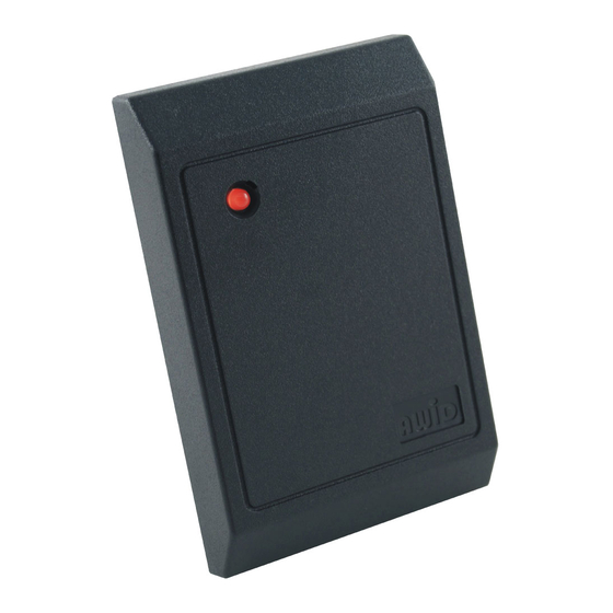
SP-6820 Low-Frequency Card Reader
SP-6820 Low-Frequency Card Reader
SP-6820 Low-Frequency Card Reader
These instructions are for AWID's Model SP-6820 reader, using compatible proximity credentials from AWID.
These instructions are for AWID's Model SP-6820 reader, using compatible proximity credentials from AWID.
These instructions are for AWID's Model SP-6820 reader, using compatible proximity credentials from AWID.
Parts List
Parts List
Parts List
(a) 1 Installation Sheet for SP-6820
(a) 1 Installation Sheet for SP-6820
(a) 1 Installation Sheet for SP-6820
(b) 1 Model SP-6820 Reader
(b) 1 Model SP-6820 Reader
(b) 1 Model SP-6820 Reader
(c) 2 #6-32 × 1" machine screw (for single-gang utility box)
(c) 2 #6-32 × 1" machine screw (for single-gang utility box)
(c) 2 #6-32 × 1" machine screw (for single-gang utility box)
Preparation
Preparation
Preparation
Reader Location: Select the reader's mounting location. The SP-6820 Reader may be screwed to a single-
Reader Location: Select the reader's mounting location. The SP-6820 Reader may be screwed to a single-
Reader Location: Select the reader's mounting location. The SP-6820 Reader may be screwed to a single-
gang utility box like a cover plate, or to a wall or other surface. On a metal surface, read range is reduced about
gang utility box like a cover plate, or to a wall or other surface. On a metal surface, read range is reduced about
gang utility box like a cover plate, or to a wall or other surface. On a metal surface, read range is reduced about
20%. The SP-6820 may be installed indoors or outdoors, but it needs protection from direct rain or snow.
20%. The SP-6820 may be installed indoors or outdoors, but it needs protection from direct rain or snow.
20%. The SP-6820 may be installed indoors or outdoors, but it needs protection from direct rain or snow.
DC Power Supply: DC power for this reader is usually supplied from the +DC and Ground terminals of the
DC Power Supply: DC power for this reader is usually supplied from the +DC and Ground terminals of the
DC Power Supply: DC power for this reader is usually supplied from the +DC and Ground terminals of the
Wiegand reader port on the system's panel. If this is not possible, use an independent power supply. Power
Wiegand reader port on the system's panel. If this is not possible, use an independent power supply. Power
Wiegand reader port on the system's panel. If this is not possible, use an independent power supply. Power
may be shared with other readers if the supply has sufficient current capacity. The power supply should be
may be shared with other readers if the supply has sufficient current capacity. The power supply should be
may be shared with other readers if the supply has sufficient current capacity. The power supply should be
close to +12 volts DC (as low as +5 volts is OK), 1 ampere capacity, linear-rated, regulated DC output.
close to +12 volts DC (as low as +5 volts is OK), 1 ampere capacity, linear-rated, regulated DC output.
close to +12 volts DC (as low as +5 volts is OK), 1 ampere capacity, linear-rated, regulated DC output.
Cable to Controller and Power Supply: 4 to 7 conductors from the reader to the system (2 wires for DC power,
Cable to Controller and Power Supply: 4 to 7 conductors from the reader to the system (2 wires for DC power,
Cable to Controller and Power Supply: 4 to 7 conductors from the reader to the system (2 wires for DC power,
2 wires for Wiegand data, and 1 to 3 wires for external LED, Beeper/Alarm, and Hold control, if used).
2 wires for Wiegand data, and 1 to 3 wires for external LED, Beeper/Alarm, and Hold control, if used).
2 wires for Wiegand data, and 1 to 3 wires for external LED, Beeper/Alarm, and Hold control, if used).
22-gauge stranded wires. Overall 100% shield for both power and data. 500 feet maximum length.
22-gauge stranded wires. Overall 100% shield for both power and data. 500 feet maximum length.
22-gauge stranded wires. Overall 100% shield for both power and data. 500 feet maximum length.
If the DC power supply is separated from the panel's reader port, the reader's
If the DC power supply is separated from the panel's reader port, the reader's
If the DC power supply is separated from the panel's reader port, the reader's
connected to both the DC power supply's Negative terminal and the panel reader port's Ground terminal.
connected to both the DC power supply's Negative terminal and the panel reader port's Ground terminal.
connected to both the DC power supply's Negative terminal and the panel reader port's Ground terminal.
If the separate DC power supply is close to the reader, run two 22-gauge cables – 2 wires for DC power,
If the separate DC power supply is close to the reader, run two 22-gauge cables – 2 wires for DC power,
If the separate DC power supply is close to the reader, run two 22-gauge cables – 2 wires for DC power,
and 3 to 6 wires for Wiegand data (including Ground) and for the external control lines, if used.
and 3 to 6 wires for Wiegand data (including Ground) and for the external control lines, if used.
and 3 to 6 wires for Wiegand data (including Ground) and for the external control lines, if used.
Both cables must be overall-shielded and earth-grounded (at the end far from the reader).
Both cables must be overall-shielded and earth-grounded (at the end far from the reader).
Both cables must be overall-shielded and earth-grounded (at the end far from the reader).
Conduit: If cables are pulled through metal conduit, the conduit should be earth-grounded (like the cables).
Conduit: If cables are pulled through metal conduit, the conduit should be earth-grounded (like the cables).
Conduit: If cables are pulled through metal conduit, the conduit should be earth-grounded (like the cables).
Installation
Installation
Installation
1. Connector – Cut off the 10-pin in-line connector from the end of the reader's cable. Discard the connector.
1. Connector – Cut off the 10-pin in-line connector from the end of the reader's cable. Discard the connector.
1. Connector – Cut off the 10-pin in-line connector from the end of the reader's cable. Discard the connector.
2. Open the Reader – Snap open the reader's front cover by inserting a wide screwdriver blade in the slot at
2. Open the Reader – Snap open the reader's front cover by inserting a wide screwdriver blade in the slot at
2. Open the Reader – Snap open the reader's front cover by inserting a wide screwdriver blade in the slot at
the bottom edge of the cover. Twist the blade gently.
the bottom edge of the cover. Twist the blade gently.
the bottom edge of the cover. Twist the blade gently.
3. Wire Connections – Connect the reader's wires to the cable(s) for power and data.
3. Wire Connections – Connect the reader's wires to the cable(s) for power and data.
3. Wire Connections – Connect the reader's wires to the cable(s) for power and data.
black
black
black
a. First, connect
a. First, connect
a. First, connect
b. Connect green to the Data-0 terminal. Connect white to the Data-1 terminal.
b. Connect green to the Data-0 terminal. Connect white to the Data-1 terminal.
b. Connect green to the Data-0 terminal. Connect white to the Data-1 terminal.
c. Connect the gray drain wire to the shield of the connecting cable.
c. Connect the gray drain wire to the shield of the connecting cable.
c. Connect the gray drain wire to the shield of the connecting cable.
If power and data are in separate cables, connect all three drains/shields together near the reader.
If power and data are in separate cables, connect all three drains/shields together near the reader.
If power and data are in separate cables, connect all three drains/shields together near the reader.
d. If the LED, Beeper/Alarm and/or Hold features are used, connect the brown, yellow and/or
d. If the LED, Beeper/Alarm and/or Hold features are used, connect the brown, yellow and/or
d. If the LED, Beeper/Alarm and/or Hold features are used, connect the brown, yellow and/or
e. At the end of the cable(s) near the panel (and near the power supply, if separate), connect the shield to a
e. At the end of the cable(s) near the panel (and near the power supply, if separate), connect the shield to a
e. At the end of the cable(s) near the panel (and near the power supply, if separate), connect the shield to a
verified earth-ground.
verified earth-ground.
verified earth-ground.
f. Last, connect
f. Last, connect
f. Last, connect
red
red
red
SP-6820 Reader Installation Sheet
SP-6820 Reader Installation Sheet
SP-6820 Reader Installation Sheet
to the panel port's Ground terminal, and, if separate, to the power supply Negative.
to the panel port's Ground terminal, and, if separate, to the power supply Negative.
to the panel port's Ground terminal, and, if separate, to the power supply Negative.
to the DC Positive terminal.
to the DC Positive terminal.
to the DC Positive terminal.
Version 2 / Doc# 041506
Version 2 / Doc# 041506
Version 2 / Doc# 041506
black
black
black
wire must be
wire must be
wire must be
blue
blue
blue
(continued)
(continued)
(continued)
Page 1 of 2
Page 1 of 2
Page 1 of 2
wires.
wires.
wires.
Advertisement
Table of Contents

Related Manuals for AWID SP-6820


Summary of Contents for AWID SP-6820
- Page 1 On a metal surface, read range is reduced about 20%. The SP-6820 may be installed indoors or outdoors, but it needs protection from direct rain or snow.
- Page 2 When mounting is finished, snap the cover on the reader. 5. Reader Test – When power is applied to the SP-6820, the LED initializes to steady-red for standby, and the 5. Reader Test – When power is applied to the SP-6820, the LED initializes to steady-red for standby, and the 5.
Need help?
Do you have a question about the SP-6820 and is the answer not in the manual?
Questions and answers