Table of Contents
Advertisement
Quick Links
Installation Sheet (Wiegand Interface)
MR-1824HiLo and
These instructions are for Model MR-1824
credentials from AWID. The "MC" model
Parts List (a) 1 Installation sheet for MR
Installation sheet for MR-1824HiLo
and MR-1824HiLoMC Reader Sets
(b) 2
MR-1824HiLo or MR-1824HiLoMC Reader
(c) 8 #6-20 × 1.375" self-tapping screw
Preparation
Reader Location: Select the readers' mounting location
metal. Mount MR-1824HiLoMC reader units on flat metal surfaces at least 8 inches square. Observe ADA
height requirements. The units may be install
are exposed directly to rain or snow, or to
The two "HiLo" units may be up to 30 feet apart. (In practice, the units may work well up to 75 feet apart.
The two "HiLo" units may be up to 30 feet apart. (In practice, the units may
Test this before making the final decision o
DC Power Supply: Use a separate power supply
Use a separate power supply – 12 volts DC, current rating 2 amperes
regulated DC output. Do not connect the reader
units are connected to the separate power supply, voltage on the
The two units may share a single 2 ampere power supply, or
he two units may share a single 2 ampere power supply, or they may have separate 1 ampere power supplies.
Cable to Controller and Power Supply: 5
power, 3 wires for Wiegand data, and 1 or 2
Overall 100% shield for both power and data
The "HiLo" units'
(b) the panel reader port's Ground or Negative
If the DC power supply is close to the
If the DC power supply is close to the "HiLo" units, you may run two cables – (a) 2 wires
power, and (b) 3 to 5 wires, 22 gauge
Additional wires connect the units' orange and violet wires (crossed over)
connect the units' orange and violet wires (crossed over) – 2 wires, 22 gauge
All cables must be overall-shielded and earth
Conduit: If cables are pulled through metal
Installation
1. Connector – Cut off the 10-pin female
connectors. All further wiring junctions will use the
All further wiring junctions will use the reader cables' individual wires.
2. Open the Units – Remove the 4 screws in the cover's beveled edges. Lift the cover off the base. Pull the
cable behind the cover gently and remove the LED assembly. Save the 4 screws for final assembly in step 5.e.
cable behind the cover gently and remove the LED assembly. Save the 4 screws for final assembly in step 5.e.
cable behind the cover gently and remove the LED assembly. Save the 4 screws for final assembly in step 5.e.
3. Mark the Mounting Holes – Use the reader unit's base as a template. Level the base. Mark the 4 mounting
holes on the wall or surface. Mark and drill the cable's clearance hole (if
holes on the wall or surface. Mark and drill the cable's clearance hole (if used). Pull the cable through the
clearance hole.
MR-1824HiLo/MC Installation Sheet
(Wiegand Interface)
MR-1824HiLoMC LF
1824HiLo and MR-1824HiLoMC readers, using
model is compensated to mount the readers directly on
1824HiLoMC Reader Sets
1824HiLoMC Reader
tapping screw
mounting locations. Mount MR-1824HiLo reader units 4 inches away from
reader units on flat metal surfaces at least 8 inches square. Observe ADA
reader units on flat metal surfaces at least 8 inches square. Observe ADA
installed outdoors, but they need protection (a non
to bright sunlight in a hot environment.
l decision on extended distance between the two units.)
connect the reader units'
power supply, voltage on the units' red and black wires should be
5 to 7 conductors from the "HiLo" set to the system (2
or 2 wires for external LED and Beeper/Alarm, if used
ower and data. 500 feet maximum length. Both "HiLo" units share this cable.
black
wire must be
be connected to both (a) the DC power supply's N
or Negative or Common terminal (for Wiegand Data Common).
for Wiegand data, and for the external control lines, if used
and earth-grounded at the ends far from the reader
pulled through metal conduit, the conduit should be earth-grounded
female connectors from the end of the reader units' cables. Discard the
connectors from the end of the reader units' cables. Discard the
Remove the 4 screws in the cover's beveled edges. Lift the cover off the base. Pull the
Remove the 4 screws in the cover's beveled edges. Lift the cover off the base. Pull the
Use the reader unit's base as a template. Level the base. Mark the 4 mounting
Use the reader unit's base as a template. Level the base. Mark the 4 mounting
| (d) 8 Plastic screw anchor
| (e) 10 Screw-hole plug for reader's cover (2 spare
| (f) 4 Cable slot plug (pre-installed in
|
red
wires to the panel's +DC terminal.
and for the external control lines, if used.
Version 2.2 / Doc# 041509
, using compatible proximity
rectly on large metal surfaces.
hole plug for reader's cover (2 spares)
installed in
MR-1824HiLoMC readers
readers)
reader units 4 inches away from
on (a non-metal housing) if they
up to 75 feet apart.
s or more, linear-rated,
terminal. When the 2 "HiLo"
red and black wires should be 12.0 volts.
have separate 1 ampere power supplies.
to the system (2 wires for DC
Beeper/Alarm, if used). 18 gauge.
Both "HiLo" units share this cable.
Negative terminal and
(for Wiegand Data Common).
2 wires, 18 gauge for DC
2 wires, 22 gauge, unshielded.
from the reader.
grounded (like the cables).
ed). Pull the cable through the
Reader Sets
(continued)
Page 1 of 3
Advertisement
Table of Contents

Related Manuals for AWID MR-1824HiLo


Summary of Contents for AWID MR-1824HiLo
- Page 1 Preparation Reader Location: Select the readers’ mounting location mounting locations. Mount MR-1824HiLo reader units 4 inches away from reader units 4 inches away from metal. Mount MR-1824HiLoMC reader units on flat metal surfaces at least 8 inches square. Observe ADA reader units on flat metal surfaces at least 8 inches square.
- Page 2 At the end of the cable(s) near the panel and near the power supply, connect the cables’ shield to a verified earth-ground. h. Last, connect to the DC power supply’s Positive terminal. MR-1824HiLo/MC Installation Sheet Version 2.2 / Doc# 041509 Page 2 of 3...
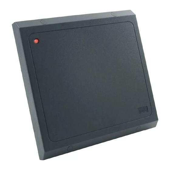
- Page 3 After you test the reader, insert the 4 screw-hole plugs in the cover over the fasteners. 6. Reader Test – When power is applied to the MR-1824HiLo, the LED initializes to steady-red for standby, and the beeper sounds. With every presentation of an AWID proximity card to the reader, the LED changes color momentarily, and the beeper sounds briefly.
Need help?
Do you have a question about the MR-1824HiLo and is the answer not in the manual?
Questions and answers