
Related Manuals for NORTHROP GRUMMAN IKA-012-QTG


Summary of Contents for NORTHROP GRUMMAN IKA-012-QTG
- Page 1 User Manual Iklwa Laser Head Gen I and Gen II CEO-UMAN-0055 Rev E © 2019 Cutting Edge Optronics, Inc. Approved for Public Release; NG19-2099...
- Page 2 20 Point West Blvd. St. Charles, MO 63301 USA Sales Support: (636) 916-4900 (follow prompts for department directory) *After office hours, please leave a voice mail message. Outside North America, contact a Northrop Grumman sales office or distributor; see the Northrop Grumman website for a list of offices.
- Page 3 Northrop Grumman. Patents Northrop Grumman Systems Corporation products are covered by U.S. and foreign patents, issued and pending. Information in this publication supersedes that in all previously published material. Specifications and price change privileges reserved. © 2019 Cutting Edge Optronics, Inc.
- Page 4 © 2019 Cutting Edge Optronics, Inc. Iklwa Laser User Manual Approved for Public Release; NG19-2099 CEO-UMAN-0055E...
- Page 5 Safety Information Product End-of-Life Handling Northrop Grumman is committed to protecting the environment. In accordance with the Waste Electrical and Electronic Equipment directive (WEEE) and Restriction of Hazardous Substances in the European Union (RoHS EU) directives, Northrop Grumman accepts the return of our products for disposal.
- Page 6 Conventions The following conventions appear in this manual: This icon denotes a caution or a warning, which advise precautions to take to avoid injury, data loss, or a system crash. Initial Capped The first letter in uppercase refers to menu options, e.g., Phase Delay, Pulse Width.
- Page 7 Shock Hazard: Use caution. Caution: Risk of danger. Refer to manual. Chassis Ground © 2019 Cutting Edge Optronics, Inc. Iklwa Laser User Manual Approved for Public Release; NG19-2099 CEO-UMAN-0055E...
- Page 8 General Safety Summary The Iklwa Laser System emits laser radiation that can permanently damage eyes and skin, ignite fires, and vaporize materials. Chapter 2: Laser Safety contains information and guidance about these hazards. To minimize the risk of injury or expensive repairs, carefully follow these instructions.
- Page 9 About This Manual This manual describes the installation, operation, and service of the Iklwa Laser System. The manual consists of the following chapters: Chapter 1: Introduction provides a theory of laser operation and a description of the Iklwa laser. ...
-
Page 10: Table Of Contents
Table of Contents Table of Contents Chapter 1: Introduction Theory of Operation ........................2 System Description ........................3 Chapter 2: Laser Safety Safety Overview ........................7 Precautions for Safe Operation ....................8 Center for Devices and Radiological Health Compliance ............8 Chapter 3: System Details Iklwa Laser Head ........................ - Page 11 Table of Contents Maintain Chiller ........................37 Check Hold Off ........................38 Extend Lifetime of Laser Diodes ....................38 Optimize Laser Performance ....................38 Chapter 6: Customer Service Module Replacement ....................... 44 Return the Instrument for Repair ..................... 44 Chapter 7: Troubleshooting Initial Checklist .........................
- Page 12 List of Figures and Tables List of Figures and Tables Table 1-1. Other Specifications Table ..................4 Figure 2-1. Radiation Control ....................9 Figure 3-1. Iklwa Front View ....................11 Figure 3-2. Iklwa Rear View ....................11 Figure 3-4. Iklwa Top View ..................... 13 Figure 3-5.
- Page 13 List of Figures and Tables Figure 4-11. Diode Power Connection (Gen II) ............... 28 Figure 4-12. Signal Connection ....................29 Figure 4-13. Signal Connection ....................29 Figure 4-15. First Giant Pulse with FPS Disabled ..............33 Figure 5-1: 40 Gram Desiccant Cartridge Top ................ 36 Figure 5-2: 40 Gram Desiccant Cartridge Bottom ..............
-
Page 14: Chapter 1: Introduction
Chapter 1: Introduction This introduction provides the following information: Theory of operation System description © 2019 Cutting Edge Optronics, Inc. Iklwa Laser User Manual Approved for Public Release; NG19-2099 CEO-UMAN-0055E... -
Page 15: Theory Of Operation
Chapter One: Introduction Theory of Operation The Iklwa Laser is a Q-switched, intra-cavity, frequency doubled, laser oscillator. The output consists of pulses of light at 532 nm wavelength and 60 ns to 100 ns pulse duration at repetition frequencies of 4,000 Hz to 12,000 Hz. It is a transverse electromagnetic mode (TEM ) laser and therefore has very high brightness. -
Page 16: System Description
Chapter One: Introduction switch to prevent the buildup of optical power in the oscillator cavity by introducing a loss greater than the available gain allowing energy to accumulate in the gain medium. The Q-switch then suddenly removes the loss, allowing the laser power to increase exponentially with each round trip of the oscillator cavity until much of the stored energy is exhausted and the gain once again falls below the loss. - Page 17 Chiller must be able to circulate coolant at the approximately 60 psi required in Northrop Grumman lasers, see final test report for each laser specific required pressure. Drain the chiller, and replace the coolant and filter monthly. This may be required more often if the system shows signs of contamination.
- Page 18 Iklwa laser head. When there is at least one gallon per minute of coolant flowing through the Iklwa laser head, the flow switch electrical contacts close. Northrop Grumman will provide the required diode array current, diode array voltage, chiller temperature, and TEC temperature operating parameters on the test report supplied with the laser.
-
Page 19: Chapter 2: Laser Safety
Chapter 2: Laser Safety Please read this chapter carefully before installing or operating the laser. A Northrop Grumman trained service engineer should perform all service and repair operations. If planning to service the laser, please follow the procedures in Chapter 5: Maintenance. Sections included in this chapter include: ... -
Page 20: Safety Overview
Chapter 2: Laser Safety Safety Overview Safe laser operation should be reviewed prior to any new installation of the Iklwa laser. CAUTION. The Iklwa laser is a Class IV, high power laser whose beam is, by definition, a safety hazard. Avoid eye or skin exposure to direct or scattered laser radiation. Avoid direct viewing of the beam or its specular reflection. -
Page 21: Precautions For Safe Operation
Post warning signs in prominent locations near the laser operation area. Use safety interlocks on all entryways. All Northrop Grumman system control electronics are supplied with interlock inputs that can be used to preclude operation with an open safety door. - Page 22 Chapter 2: Laser Safety Figure 2-1. Radiation Control © 2019 Cutting Edge Optronics, Inc. Iklwa Laser User Manual Approved for Public Release; NG19-2099 CEO-UMAN-0055E...
-
Page 23: Chapter 3: System Details
Chapter 3: System Details This chapter discusses the operation of the Iklwa laser: Iklwa laser head Iklwa wiring interface Closed loop chiller © 2019 Cutting Edge Optronics, Inc. Iklwa Laser User Manual Approved for Public Release; NG19-2099 CEO-UMAN-0055E... -
Page 24: Iklwa Laser Head
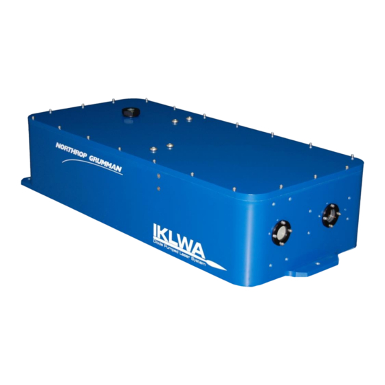
Chapter Three: System Details Iklwa Laser Head The Iklwa laser head measures 24" x 8" x 6" (not including the connectors at the rear of the laser). The laser emission indicator is located on the side of the unit. The output window is positioned 76.2 mm (3") from the bottom of the Iklwa laser and 99.7 mm (3.93") from the side with the emission indicator. - Page 25 Chapter Three: System Details Figure 3-3. Iklwa Gen II Rear View The alignment openings are located on both front and back panels and are sealed by screws to prevent emission during normal operation. The service technician can remove the screws and use a HeNe laser to aid alignment. WARNING.
-
Page 26: Iklwa Wiring Interface
Chapter Three: System Details Figure 3-4. Iklwa Top View Iklwa Wiring Interface Laser Signal Connector: MS3476L16-26S (Connector) M85049/52-1-16N (Backshell) Figure 3-5. Iklwa J1 Connector Interface Table 3-1 J1 Connections Signal Description Laser-On LED 24 V. Keep isolated from other circuits Positive Laser on lamp on the laser housing. - Page 27 (should only be closed when greater than 1 gpm coolant is flowing through the laser head; otherwise, open circuit) Not Used Pin K shorted to pin a for Northrop Grumman test electronics Not Used Pin a shorted to pin K for Northrop Grumman test...
- Page 28 Chapter Three: System Details Table 3-2. J2 Connections Signal Description Array Drive Positive Divide current with Pin B. Voltage and current per test report. Approximately 20V and 25A Array Drive Positive Divide current with Pin A. Voltage and current per test report.
-
Page 29: Closed Loop Chiller
More than one third of these damaged lasers result from cooling problems. Coolant problems almost always require the replacement of the diode arrays - the single most expensive component in Northrop Grumman lasers. This section describes how to avoid damaging arrays. - Page 30 9 or the filter or coolant show any discoloration. When not using Northrop Grumman drive electronics, verify that flow sensor interrupts current to diodes less than 1s after a low flow condition occurs.
- Page 31 Q-switch when coolant flow rate drops below 1 gpm (3.7 lpm) When setting up the laser system for the first time, Northrop Grumman highly recommends testing the flow interlock before firing. By testing the interlock with no current to the laser, there is no risk of damaging the laser.
- Page 32 Chapter Three: System Details Controlling the humidity level inside the laser is important to extend the lifetime of SHG crystal. The desiccant cartridge on the top cover can help to removes excess moisture from inside the laser head. WARNING. Do not operate the laser without a functional desiccant cartridge. Condensation on the diode arrays can seriously damage the laser and may void warranty.
- Page 33 Chapter Three: System Details Table 3-6. Table of Air Condensation Temp at Given Ambient Air Temp (° C) and Rel. Humidity (%) Relative Humidity 100% -43.9 -20.2 -11.9 -6.8 -3.0 10.0 -42.6 -18.7 -10.3 -5.0 -1.2 10.4 12.0 -41.4 -17.1 -8.6 -3.3 10.6...
-
Page 34: Chapter 4: Installation And Operation
External triggering and FPS The purchaser is responsible for any loss and injury during installation and use of the laser system. Northrop Grumman recommends that a qualified service technician install and maintain the laser. If intending to service, please follow the following procedures. -
Page 35: Unpacking The Laser System
Chapter Four: Installation and Operation Unpacking The Laser System The Northrop Grumman Iklwa laser was carefully packed for shipment. If the carton appears to have been damaged in transit, have the shipper’s agent present when the laser is unpacked. Inspect the unit for dents, scratches, or other evidence of damage as it is unpacked. If damage is discovered, immediately file a claim against the carrier and notify the Northrop Grumman representative. -
Page 36: Chiller Set Up
Please follow the proper procedures to clean the chiller before it is connected to the laser head. These procedures are listed on the CD (compact disc) shipped with the unit. They are also available through Northrop Grumman technical service. WARNING. - Page 37 Chapter Four: Installation and Operation Figure 4-3 depicts the chiller with connected water hoses. Figure 4-3. Chiller Assembled with Water Hoses and Filter © 2019 Cutting Edge Optronics, Inc. Iklwa Laser User Manual Approved for Public Release; NG19-2099 CEO-UMAN-0055E...
-
Page 38: Connections To The Laser Head
Chapter Four: Installation and Operation Connections to the Laser Head Figures 4-4 and 4-5 depict the connectors on the rear panel of the Iklwa laser. All of the connectors are clearly labeled. Figure 4-4 Connectors on the rear panel of the Iklwa laser (Gen I) Figure 4-5 Connectors on the rear panel of the Iklwa laser (Gen II) Follow these steps to connect the laser head: ©... - Page 39 Chapter Four: Installation and Operation 1. Connect the plumbing. As shown in Figures 4-6 and 4-7, push the barb fittings of water hose connectors gently into the COOLANT IN and COOLANT OUT ports by following the flow path direction. Wetting the o- rings of the quick disconnect fittings and receptacles can prevent the o-ring from being damaged.
- Page 40 Chapter Four: Installation and Operation 2. Connect RF Cable: Connect the Q-switch RF cable to the BNC connector on the laser head (see Figures 4-8 and 4-9). Once aligned, the connector can be pushed in. Turn the locking ring of the connector in the clockwise direction until it is locked.
- Page 41 Chapter Four: Installation and Operation 3. Connect diode power. Connect the female connector of the diode power cable to the J2 connector on the laser head (see Figures 4-10 and 4-11). Once aligned, the connector can be pushed in. Turn the locking ring of the connector in the clockwise direction until it is locked.
- Page 42 Chapter Four: Installation and Operation 4. Connect laser signal. Align the female connector of the laser signal cable to the J1 connector on the laser head. Once aligned, the connector can be pushed in. Turn the locking ring of the connector in the clockwise direction until it is locked as shown in Figures 4-12 and 4-13.
-
Page 43: First Time Laser Power-Up Procedure
Chapter Four: Installation and Operation First Time Laser Power-Up Procedure Remove the cap that protects laser output window and make sure the window is clean. If not, gently clean it with a lens tissue and methanol. Turn on the chiller and verify its settings: 1. -
Page 44: Daily Operation
Chapter Four: Installation and Operation 6. Once all the parameters are set correctly, and temperatures of TEC Controller and chiller are stabilized, set the current at 10 A and begin current flow to the diodes. Open the laser shutter. Gradually increase the current until the laser is firing at very low power. -
Page 45: Output Power Control
Chapter Four: Installation and Operation Manual Interrupt Procedure 1. Close the shutter. 2. Resume operation by opening the shutter again. Laser will resume operation with no audible warning. NOTE: The laser diodes are operated at set pumping current while the shutter is closed. Shut Down Procedure 1. - Page 46 Chapter Four: Installation and Operation Figure 4-15. First Giant Pulse with FPS Disabled CAUTION. The FPS has to be enabled and parameters for FPS have to be set properly. Failure to suppress the first giant pulse may cause the internal optical damage as well as damage to the work piece.
-
Page 47: Chapter 5: Maintenance
Chapter 5: Maintenance The chapter contains information in these sections: Prepare for shipment Purge housing Replace desiccant cartridge Maintain chiller Check hold off Extend lifetime of laser diodes Optimize laser performance © 2019 Cutting Edge Optronics, Inc. Iklwa Laser User Manual Approved for Public Release;... -
Page 48: Prepare For Shipment
Also, the housing interior can be purged with Class 0 air using the valve on the rear of the housing. The inlet line is the stemmed valve and is opened and closed by rotating the knob on the valve end. Please contact Northrop Grumman before attempting this procedure. -
Page 49: Replace Desiccant Cartridge
If the desiccant cartridges are exhausted in a short time frame (e.g., 2 weeks) without the laser head having been opened, contact Northrop Grumman technical service. Figure 5-1: 40 Gram Desiccant Cartridge Top Figure 5-2: 40 Gram Desiccant Cartridge Bottom Figure 5-3. -
Page 50: Maintain Chiller
Iklwa laser head is an industry standard part. Replacement cartridges may be purchased from: 40 Gram: Northrop Grumman CEO or directly from AGM Container Controls, Inc. telephone number 800-995-5590. Desiccant cartridge Northrop Grumman CEO part no. 42-228 ... -
Page 51: Check Hold Off
For this procedure, a green light should be visible from the laser. In the absence of any visible output, please review Chapter 7: Troubleshooting or contact Northrop Grumman for assistance. To obtain the best performance, small adjustments may optimize the laser. - Page 52 Chapter Five: Maintenance Both the laser bench temperature and environmental temperature significantly impact the laser power. Wait for the laser to be thermally stabilized before attempting any adjustment. 2. Check the settings of the diode power supply and chiller. Check the performance with all items set to the values on the laser test report. The water flow rate and coolant temperature have a significant impact on the laser performance.
- Page 53 Chapter Five: Maintenance Figure 5-6 illustrates an example of the dependence of the output power and pulse-to- pulse instability of the Iklwa laser to operating current. Notice that the laser power increases as the operating current is increased. The laser reached peak power around 23 A.
- Page 54 Chapter Five: Maintenance Laser Out Figure 5-7. Accessible Holes for HR and HM Cavity Mirror Adjustment e. Optimize power: Make small adjustments to the horizontal angle of HM mirror and observe the output power. Once a maximum is found, adjust the vertical control of HM mirror to maximize power.
- Page 55 Chapter Five: Maintenance Continue if improvement is noted. If there is no improvement, try the opposite direction. Perform the same procedure with the vertical adjustments of the HM and HR mount. Typically, SHG temperature adjustment is not needed when adjusting vertically.
-
Page 56: Chapter 6: Customer Service
Chapter 6: Customer Service When calling for service in the U.S., dial (636) 916-4900. To phone for service in other countries, contact the sales agent. This chapter provides reference to types of customer service needs: Module replacement Return the instrument for repair ©... -
Page 57: Module Replacement
Return the Instrument for Repair A return merchandise authorization (RMA) is required prior to shipping any instruments to Northrop Grumman. Contact Northrop Grumman or a local distributor for RMA and shipping instructions. CAUTION . Failure to obtain proper shipping instructions may result in damage to the instrument. -
Page 58: Chapter 7: Troubleshooting
Chapter 7: Troubleshooting This chapter is intended to provide possible solutions to common problems encountered with the Iklwa laser during normal use. For more information please see the troubleshooting guide that is on the owner’s manual CD supplied with the laser. The following sections can be found in this chapter: ... -
Page 59: Initial Checklist
Chapter Seven: Troubleshooting Initial Checklist Before adjusting or attempting troubleshooting procedures, verify the following. Additional information is available in the troubleshooting guide that was supplied with the laser: Verify the diode current supply is operating at the correct output current and the current set point matches the test data sheet supplied with the laser. - Page 60 Internal optical damage to the laser, contaminated rod, or aging diodes: If the laser power cannot be restored after optimization, contact Northrop Grumman for service. No Output Power Verify the operating current is set at the operation point.
- Page 61 Chapter Seven: Troubleshooting Laser Beam Quality Figure 7-1 shows a typical laser output beam at operating current. Figure 7-1 – Typical Beam Profile at Beam Waist, Farfield at Operating Current If the laser shows an abnormal profile such as a split beam or alternate beam structure, do the following: Not Operating at Correct Parameters: Verify that all operating parameters match the values on the ATP Test Report.
- Page 62 Inspect all optics including the diode module rod. Internal optical damage to the laser, contaminated rod, or aging diodes: If the laser power cannot be restored after optimization, contact Northrop Grumman for service. © 2019 Cutting Edge Optronics, Inc. Iklwa Laser User Manual Approved for Public Release;...
-
Page 63: Appendix A: System International Units
Appendix A: System International Units The following System International (SI) units, abbreviations, and prefixes are used throughout Northrop Grumman user manuals: Quantity Unit Symbol Abbrv. Prefixes mass gram tera length meter giga time second mega frequency Hertz kilo force Newton... -
Page 64: Appendix B: Acronyms
Appendix B: Acronyms Acronym Description ACGIH American Conference of Government Industrial Hygienists ANSI American National Standards Institute Acousto-optic Anti-Reflective Acceptance Test Procedure CDRH Center for Devices and Radiological Health Continuous Wave First Pulse Suppression HeNe Helium Neon Harmonic Mirror High-Reflection International Electrotechnical Commission Lithium Triborate... - Page 65 Appendix B: Acronyms Acronym Description Pounds per Square Inch Radio Frequency Relative Humidity Root Mean Square Second Harmonic Generator Thermal Electric Cooler TEM00 Transverse Electromagnetic Mode Transistor - Transistor Logic Ultraviolet Volts, Alternating Current © 2019 Cutting Edge Optronics, Inc. Iklwa Laser User Manual Approved for Public Release;...
-
Page 66: Index
Index Index Alignment, 13, 42, 48 Laser Diodes, 2, 4, 5, 19, 20, 29, 33, 39, 41, 45, 47, 48, 49 Amplifier, 2, 3 Laser on Indicator, 5, 15 Aperture, 3, 13 Laser Optimization, 32, 39, 42, 48, 49 ATP Test Report, 5, 19, 31, 32, 39, 40, 47, 49 Laser Safety Beam Conversion, 2 Emission, v...
Need help?
Do you have a question about the IKA-012-QTG and is the answer not in the manual?
Questions and answers