Table of Contents
Advertisement
Quick Links
Sperry Marine
User, Technical and Service Manual
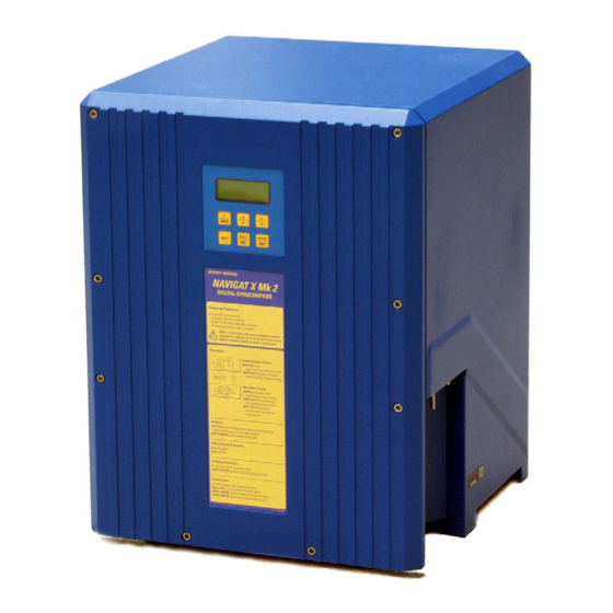
NAVIGAT X MK 2
Digital Gyrocompass System
Rev. AA, 07 May 2004
056341
Head Office and Freight: Woltmanstrasse 19, D-20097 Hamburg, Germany
Correspondence Address: P.O. Box 10 47 09, D-20032 Hamburg, Germany
Tel.: ++49-40-299 00-0, Fax: ++49-40-299 00-298, E-mail Service: Kai_Stahl@sperry-marine.com
Advertisement
Table of Contents

Related Manuals for NORTHROP GRUMMAN Sperry Marine NAVIGAT X MK 2


Summary of Contents for NORTHROP GRUMMAN Sperry Marine NAVIGAT X MK 2
- Page 1 Sperry Marine User, Technical and Service Manual NAVIGAT X MK 2 Digital Gyrocompass System Rev. AA, 07 May 2004 056341 Head Office and Freight: Woltmanstrasse 19, D-20097 Hamburg, Germany Correspondence Address: P.O. Box 10 47 09, D-20032 Hamburg, Germany Tel.: ++49-40-299 00-0, Fax: ++49-40-299 00-298, E-mail Service: Kai_Stahl@sperry-marine.com...
- Page 2 056341 Rev. AA NAVIGAT X Mk 2 Copyright © Northrop Grumman Sperry Marine, Hamburg, 2004 This document contains proprietary information of Northrop Grumman Sperry Marine, Hamburg, Germany. Any reproduction or publication of this document or any portions thereof without the prior written consent of Sperry Marine is expressly prohibited.
-
Page 3: Table Of Contents
NAVIGAT X Mk 2 056341 Rev. AA Contents Safety Precautions 1 Description 1.1 Design and Main Features................... 1–1 1.2 Data and Signal Interfaces .................. 1–2 1.3 Technical Data ...................... 1–3 2 Operation 2.1 Operating Conditions................... 2–1 2.2 Power-up Sequence..................... 2–1 2.3 Display and Control Elements................ - Page 4 NAVIGAT X Mk 2 056341 Rev. AA 3 Errors and Alarms 3.1 Alarm Indication ....................3–1 3.1.1 Audible Alarm Indication ................. 3–1 Invalid Function ................3–1 System Alarm ................... 3–1 3.1.2 Visual Alarm Indication................3–1 3.1.3 Acknowledging Alarms / Muting the Audible Alarm......3–1 3.2 Error Messages ....................
- Page 5 NAVIGAT X Mk 2 056341 Rev. AA 6 System Configuration 6.1 Configuration Menu (Service Setup 1)............... 6–1 6.1.1 Service Setup 1 – Access Code..............6–1 6.1.2 Service-Setup 1 – Overview ..............6–2 6.1.3 Service Setup 1 – Parameters ..............6–5 Interface I/O ..................
- Page 6 NAVIGAT X Mk 2 056341 Rev. AA 8 Gyroshpere Installation and Service 8.1 Safety Notes......................8–1 8.1.1 Material Specification, Risk and Safety Information ......8–1 8.2 Gyrosphere Handling and Storage Instructions ..........8–2 8.3 Installation of the Gyrosphere ................8–3 8.3.1 Installing the Gyrosphere in the Gyrosphere Container .......
-
Page 7: Safety Precautions
NAVIGAT X Mk 2 056341 Rev. AA Safety Precautions The following safety notice conventions are followed throughout this manual: A Warning contains an operating or maintenance procedure, practice, condition, statement, etc., which, if not strictly observed, could result in injury or death of personnel. Special warning symbols are used in this manual to indicate Danger from toxic substances, Danger of electrical shock. - Page 8 NAVIGAT X Mk 2 056341 Rev. AA...
-
Page 9: Description
NAVIGAT X Mk 2 056341 Rev. AA 1 Description 1.1 Design and Main Features The NAVIGAT X MK 2 is a microprocessor controlled gyrocompass system with integrated automatic North speed error correction. The single unit design with a polyurethane hard foam housing allows the gyro- compass to be installed on any bridge. -
Page 10: Data And Signal Interfaces
056341 Rev. AA NAVIGAT X Mk 2 1.2 Data and Signal Interfaces The NAVIGAT X MK 2 provides input interfaces for a magnetic compass (flux- gate sensor or electronic compass), speed log and position receiver. The system provides four serial data outputs to analogue or digital repeaters (including short-circuit-proof 24 VDC repeater power supply), two RS422 sen- sor data outputs, a Fast output interface (reduced dataset) and a Superfast out- put interface (adjustable baudrate, max. -
Page 11: Technical Data
NAVIGAT X Mk 2 056341 Rev. AA 1.3 Technical Data heading display ............4-digit max. follow-up speed..........100°/s mean settling time............< 3 h freedom of roll and pitch ..........±40° Accuracies lin. mean settle point error ..........≤ 0.1° sec lat static error ................ - Page 12 056341 Rev. AA NAVIGAT X Mk 2 Data Outputs repeater (4x NMEA)............. gyrocompass heading magnetic compass heading rate of turn heading reference status 4x supply 24 VDC, max. 7 W each sensor data (2 x RS422) ..........gyrocompass heading magnetic compass heading rate of turn position speed...
-
Page 13: Operation
NAVIGAT X Mk 2 056341 Rev. AA 2 Operation 2.1 Operating Conditions The permitted ambient temperature for the operation of the gyrocompass sys- tem is -10 – +55 °C. The NAVIGAT X MK 2 may no longer be operated when the ambient tempera- ture at the gyrocompass’... -
Page 14: Display And Control Elements
056341 Rev. AA NAVIGAT X Mk 2 2.3 Display and Control Elements 2.3.1 Control and Display Unit The NAVIGAT X MK 2 is operated from the integrated Control and Display Unit. The control keys provide access to the compass’ multilevel display and operat- ing menu. -
Page 15: Selecting The Heading Reference
NAVIGAT X Mk 2 056341 Rev. AA 2.4 Selecting the Heading Reference The operator may select one of the available heading sources as the heading reference for the devices connected to the gyrocompass system (e.g. autopilot, repeaters etc.). The selected heading reference is indicated by an arrow symbol (>) in front of the corresponding heading value in the display. -
Page 16: Adjusting The Display Brightness
056341 Rev. AA NAVIGAT X Mk 2 2.5 Adjusting the Display Brightness Press key to increase the display brightness. Press key to reduce the display brightness. 2.6 Acknowledging Alarms / Muting the Audible Alarm On alarm, press keys to acknowledge the alarm and clear the alarm message from the display screen. -
Page 17: Operating Menu
NAVIGAT X Mk 2 056341 Rev. AA 2.8 Operating Menu The data display screens and the manual settings, user and service setup modes are accessed via a multilevel operating menu. 2.8.1 Entering / Quitting the Main Menu From the heading display screen, MK2 HEADING press key to go to the main menu >F1... -
Page 18: Selecting Parameter Settings
056341 Rev. AA NAVIGAT X Mk 2 2.8.3 Selecting Parameter Settings In a number of sub-menus, parameters are set by selecting one out of several options. Flashing up/down arrow symbols indicate that the operator is expected to select the required setting. When flashing arrows are shown: Press key to scroll up/down through MAN.SETTINGS... -
Page 19: Display Data Menu
NAVIGAT X Mk 2 056341 Rev. AA 2.9 Display Data Menu The Display Data menu provides access to the data display screens. The se- lected display screen remains active until the user selects a different screen or quits the display data menu. Fig. -
Page 20: Manual Settings Menu
056341 Rev. AA NAVIGAT X Mk 2 2.10 Manual Settings Menu The Manual Settings Menu contains operational settings which may require to be altered by the operator during normal operation. 2.10.1 Manual Settings – Overview Fig. 2–3: The Manual MAN.SETTINGS GYRO 1 Settings Menu F1 SPEED/LATITUDE speed/latitude input settings... -
Page 21: Manual Settings - Parameters
NAVIGAT X Mk 2 056341 Rev. AA 2.10.2 Manual Settings – Parameters 2.10.2.1 Speed/Latitude Sets the parameters for speed and latitude inputs used for the automatic North speed error correction. Speed/Lat Mode Function: Selects between automatic and manual input of the actual speed and latitude. -
Page 22: Hdg. Diff. Alarm
056341 Rev. AA NAVIGAT X Mk 2 2.10.2.2 Hdg. Diff. Alarm Sets the parameters for the heading difference alarm function. If the difference between the heading data from the monitored compasses exceeds the set threshold, the heading difference alarm relay is actuated. Simultaneously, an error message is displayed and an audible alarm given. -
Page 23: Magnetic Variation
NAVIGAT X Mk 2 056341 Rev. AA 2.10.2.3 Magnetic Variation Sets the parameters for the magnetic variation. Magnetic compass heading data is automatically corrected according to the effective variation value. If automatic input is active, the magnetic variation is read from NMEA sen- tences received at the position or magnetic compass interface. -
Page 24: North Speed Error Correction
056341 Rev. AA NAVIGAT X Mk 2 2.10.2.4 North Speed Error Correction Function: Activates /deactivates the automatic North speed error correction. If automatic north speed error correction is active, the system perma- nently calculates the north speed error from the current speed and position and corrects the gyrocompass heading data accordingly. -
Page 25: Settings Naviprint
NAVIGAT X Mk 2 056341 Rev. AA 2.10.2.5 Settings NAVIPRINT Sets the parameters for the printout of an act. heading graph using the nav. data printer NAVIPRINT. Naviprint Function: Switches printing on/off. Settings: ON output to printer active no output to printer Pap. -
Page 26: Settings Rot / Time Const. Rot
056341 Rev. AA NAVIGAT X Mk 2 2.10.2.6 Settings RoT / Time Const. RoT Function: Sets the damping time constant for the analogue rate-of-turn out- put. The larger the constant, the stronger sudden peaks of the out- put voltage are damped. Settings: time const.: 0.0 –... -
Page 27: User Setup
NAVIGAT X Mk 2 056341 Rev. AA 2.11 User Setup The User Setup menu provides access to the internal clock, software version data and the magnetic compass calibration table. 2.11.1 User Setup – Overview Fig. 2–4: The User Setup USER SETUP Menu F1 DATE/TIME DATE/TIME... -
Page 28: User Setup - Parameters
056341 Rev. AA NAVIGAT X Mk 2 2.11.2 User Setup – Parameters 2.11.2.1 Date/Time Sets the parameters for the internal clock. Date and time information is accessi- ble via the display data menu. If a nav. data printer NAVIPRINT is connected to the compass system, the internal clock provides the time reference for the printer. -
Page 29: Software Version
NAVIGAT X Mk 2 056341 Rev. AA 2.11.2.2 Software Version Function: Displays the version numbers of the system software on the main PCB and of an external control and display unit (if applicable). Settings: No settable parameters, this menu is read-only. 2.11.2.3 Magnetic Compass Calibration Table Selects between the calibrated/uncalibrated display of the magnetic compass... - Page 30 056341 Rev. AA NAVIGAT X Mk 2 Page 2-18 2: Operation...
-
Page 31: Errors And Alarms
NAVIGAT X Mk 2 056341 Rev. AA 3 Errors and Alarms 3.1 Alarm Indication 3.1.1 Audible Alarm Indication 3.1.1.1 Invalid Function A single short beep indicates that an invalid function was selected. This is the case, e.g. if the operator attempts to change the heading reference while the Auto steering mode is active. -
Page 32: Error Messages
056341 Rev. AA NAVIGAT X Mk 2 3.2 Error Messages The following table lists the error messages which may appear on the display and in the error list when a system alarm is active. Message Message in on Display Error List Remarks Corrective Action GYRO FAILURE... -
Page 33: Service Info Menu (Service Setup 2)
NAVIGAT X Mk 2 056341 Rev. AA 3.3 Service Info Menu (Service Setup 2) The Service Setup 2 provides access to system status information which is used during installation and for troubleshooting. Furthermore, an option is provided to reset the system without cycling the power (warm start). 3.3.1 Service Setup 2 –... -
Page 34: Service Setup 2 - Parameters
056341 Rev. AA NAVIGAT X Mk 2 3.3.3 Service Setup 2 – Parameters 3.3.3.1 Gyrosphere Data Function: Displays the gyrosphere operating data Displays: Temperature The ambient temperature around the gyrosphere container. Ph. Bridge The follow-up circuit phase bridge voltage. Gyro Curr. The gyrosphere current. -
Page 35: Preventive Maintenance
NAVIGAT X Mk 2 056341 Rev. AA 4 Preventive Maintenance 4.1 Maintenance Specifications The gyrosphere is the only component of the NAVIGAT X Mk 2 which requires regular maintenance. Except for the removal of the complete gyroshpere container to protect it from low ambient temperatures, any maintenance or service work on the compass system is to be carried out by authorized service personnel only. -
Page 36: Maintenance By Shipboard Personnel
056341 Rev. AA NAVIGAT X Mk 2 4.2 Maintenance by Shipboard Personnel 4.2.1 Protecting the Gyrosphere from Low Ambient Temperatures The permitted ambient temperature for the operation of the gyrocompass sys- tem is -10 – +55 °C. The NAVIGAT X MK 2 may no longer be operated when the ambient tempera- ture at the gyrocompass’... -
Page 37: Removing The Gyrosphere Container From The Compass Housing
NAVIGAT X Mk 2 056341 Rev. AA 4.2.2 Removing the gyrosphere container from the compass housing The gyrosphere container with the gyrosphere installed must be handled very carefully. The container must be kept in an upright position at all times. Caution Parts required –... - Page 38 056341 Rev. AA NAVIGAT X Mk 2 Gently turn the bellows, until the largest of the three coupling seats in the bayo- net collar points towards the front of the housing. the seat is marked by a green dot on the collar. Put both hands around the container and lift it up, so that the coupling tongues disengage from their seats in the bayo-...
-
Page 39: Re-Installing The Gyrosphere Container In The Compass Housing
NAVIGAT X Mk 2 056341 Rev. AA 4.2.3 Re-installing the gyrosphere container in the compass housing The gyrosphere container with the gyrosphere installed must be handled very carefully. The container must be kept in an upright position at all times. Caution Parts required –... - Page 40 056341 Rev. AA NAVIGAT X Mk 2 Put both hands around the container and lift it into the collar, so that the coupling tongues slide into the corresponding grooves in the bayonet. While supporting the container with both palms, put the thumbs on the rim of the collar and turn the collar to the right Gently lower the container.
-
Page 41: Power-Up Function Test
NAVIGAT X Mk 2 056341 Rev. AA 4.2.4 Power-up Function Test To verify the correct operation of the compass, the power-up sequence and the settling of the compass is observed. The gyrosphere current is periodically checked during the first 45 minutes of operation and the final heading output is checked after the compass has settled. - Page 42 056341 Rev. AA NAVIGAT X Mk 2 In the Service Setup 2 (code 610), select the gyrosphere data sub-menu to observe the gyrosphere current: Directly after power-up, the gyrosphere current GYROSHPERE DATA should not exceed 550 mA. The current will TEMPERATURE 42 °C gradually fall while the gyrosphere settles.
-
Page 43: Maintenance By Service Personnel
NAVIGAT X Mk 2 056341 Rev. AA 4.3 Maintenance by Service Personnel 4.3.1 Gyrosphere Installation and Service Gyrosphere installation and service are described in Chapter 8 of this manual. 4.3.2 Updating the System Software A system software update is installed by exchanging the pre-programmed flash-memory chip, IC 35, on the main PCB. - Page 44 056341 Rev. AA NAVIGAT X Mk 2 De-energize the system and safeguard the main and backup power sup- plies against accidental switching-on. Unscrew the 5 mm Allen-head screws of the compass housing door and take off the door from the housing. Disconnect the grounding strap be- tween door and housing.
-
Page 45: Installation
NAVIGAT X Mk 2 056341 Rev. AA 5 Installation The NAVIGAT X Mk 1 gyrocompass system comprises a compass housing com- plete with installed baseplate assembly and main PCB, a gyrosphere container, a gyrosphere and an installation and replacement parts kit. The gyrosphere is contained in a carrying box, which is packed in a transport container. -
Page 46: Electrical Installation
056341 Rev. AA NAVIGAT X Mk 2 5.2 Electrical Installation Each gyrocompass system is supplied with either a general or an installation- specific connection diagram. The connection diagram provides the information needed to fit and connect all cables required by the gyrocompass system. Ship's cables are directly connected to screw-down terminals on the main PCB. -
Page 47: Initial System Configuration
NAVIGAT X Mk 2 056341 Rev. AA 5.4 Initial System Configuration To make the system fully functional, the configuration parameters need to be set to the required values in the Service Setup 1. Additionally, the applicable standard operational settings should be entered in the Manual Settings menu. To configure the system: Check that the wiring has been carried out completely. - Page 48 056341 Rev. AA NAVIGAT X Mk 2 To finalize the installation: Select the required speed/latitude modes, North speed error correction, nav. data printer and rate of turn output settings in the Manual Settings menu. After configuration, function-check the system with all connected equip- ment in operation.
-
Page 49: Alignment Error Correction
NAVIGAT X Mk 2 056341 Rev. AA 5.4.1 Alignment Error Correction In order to obtain correct heading data, the existing alignment error (i.e. the an- gular difference between the compass orientation and the vessel's fore-and-aft axis) must be determined and the required correction applied. Alignment error is 0°... -
Page 50: Magnetic Compass Calibration
056341 Rev. AA NAVIGAT X Mk 2 5.4.2 Magnetic Compass Calibration Ideally, the magnetic heading displayed at the NAVIGAT X Mk 2 would exactly match the indication of the steering magnetic compass (at a mag. var. of 0.0°). In practice, deviations will occur between the steering magnetic compass' heading and the heading data transmitted by an electronic magnetic compass. - Page 51 NAVIGAT X Mk 2 056341 Rev. AA To store the calibration table: Select the Mag. C. Cal. Table menu in the User Setup. Press keys to go to the calibration table USER SETUP entry screen. MAG.C.CAL. TABLE ON ý F1 TO ENTER VALUES Enter the required heading/correction value pairs: increase / decrease value at cursor posi- USER SETUP...
- Page 52 056341 Rev. AA NAVIGAT X Mk 2 Page 5-8 5: Installation...
-
Page 53: System Configuration
NAVIGAT X Mk 2 056341 Rev. AA 6 System Configuration 6.1 Configuration Menu (Service Setup 1) The Service Setup 1 provides access to the system parameters which need to be set according to the specific installation. Furthermore, the Service Setup 1 provides a test mode to check the operation of the serial and 6 step/°... -
Page 54: Service-Setup 1 - Overview
056341 Rev. AA NAVIGAT X Mk 2 6.1.2 Service-Setup 1 – Overview SERVICE SETUP 1 F1 INTERFACE I/O INTERFACE I/O interface configuration F2 ANALOG ROT OUTP. F3 PROTOCOL TYPE ü MAG.HDG.INP. NMEA-HDM NMEA-HCHDT NMEA-HDG PLATH-MAGN NAVIPILOT COMP.MONITOR SPEED INPUT 200 Pulse/NM NMEA POS INPUT NMEA-GLL... - Page 55 NAVIGAT X Mk 2 056341 Rev. AA contd. from previous page SERVICE SETUP 1 F1 INTERFACE I/O F2 ANALOG ROT OUTP. ANALOG ROT OUTP. settings analog ROT output F3 PROTOCOL TYPE ü sc. factor: 0.1 – 999.9 mV/˚/min zero offset: -999 – +999 mV PROTOCOL TYPE NMEA output protocol standard IEC 61162-1...
- Page 56 056341 Rev. AA NAVIGAT X Mk 2 contd. from previous page SERVICE SETUP 1 û F1 GEN. ALARM SETUP GEN. ALARM SETUP conditions for actuation F2 NAME OF GYRO of general alarm relay F3 TEST MODE ON ALL ALARMS ON FATAL ALARMS NAME OF GYRO gyro ID setting ID-No.
-
Page 57: Service Setup 1 - Parameters
NAVIGAT X Mk 2 056341 Rev. AA 6.1.3 Service Setup 1 – Parameters 6.1.3.1 Interface I/O Mag. Hdg. Inp. Function: Selects the data protocol for the magnetic heading input. Settings: NMEA-HDM Magnetic heading is read from the NMEA $--HDM sentence. NMEA-HCHDT Magnetic heading is read from the NMEA $HCHDT sentence NMEA-HDG... -
Page 58: Pos. Input
056341 Rev. AA NAVIGAT X Mk 2 Pos. Input Function: Selects the position data input protocol Settings: NMEA-GLL Position is read from the NMEA $--GLL sentence NMEA-GGA Speed is read from the NMEA $--GGA sentence Sens. D.M. Outp. Function: Selects the NMEA output sentence for magnetic heading data at the Sens Data output Settings: NMEA-HCHDM Magnetic heading is transmitted using the NMEA $HCHDM sen-... -
Page 59: S/Fast M. Outp
NAVIGAT X Mk 2 056341 Rev. AA S/Fast M. Outp. Function: Selects the NMEA output sentence for magnetic heading data at the Superfast and Fast Outputs Settings: NMEA-HCHDM Magnetic heading is transmitted using the NMEA $HCHDM sen- tence. The transmitted value is the magnetic heading as displayed on the NAVIGAT X Mk 2 display, i.e. -
Page 60: Nmea Superfast
056341 Rev. AA NAVIGAT X Mk 2 NMEA Superfast Function: Selects the data protocol at the Superfast output Settings: 4800 BAUD The output transmits NMEA data at 4800 Baud 9600 BAUD The output transmits NMEA data at 9600 Baud 19200 BAUD The output transmits NMEA data at 19200 Baud 38400 BAUD The output transmits NMEA data at 38400 Baud... -
Page 61: Analog Rot Outp
NAVIGAT X Mk 2 056341 Rev. AA 6.1.3.2 Analog ROT Outp. Sc. Factor Function: Sets the scale factor for the analogue Rate of Turn output Setting: 0.1 – 999.9 mV/° Zero Offset Function: Sets the zero-point offset for the analogue Rate of Turn output Settings: -999 –... -
Page 62: Hdg. Sel
056341 Rev. AA NAVIGAT X Mk 2 Hdg. Sel. Function: Sets the heading reference selector Settings: CDU 1 The heading reference is selected using the gyro’s control and dis- play unit COMP . MON The heading reference is selected from a NAVITWIN III compass monitor AUTOPILOT The heading reference is selected from a NAVIPILOT heading con-... -
Page 63: Name Of Gyro
NAVIGAT X Mk 2 056341 Rev. AA 6.1.3.8 Name Of Gyro Function: Selects the Gyrocompass ID Settings: ID-No. 1 The compass ID is „1“ . Standalone gyro or main gyro in a dual or tri- ple gyro system. ID-No. 2 The compass ID is „2“... -
Page 64: Factory Settings Menu (Technical
056341 Rev. AA NAVIGAT X Mk 2 6.2 Factory Settings Menu (Technical Pages) The Technical Pages provide access to a number of factory-set parameters which need not normally be altered. However, should the system software need to be exchanged, these settings will be lost and must be re-entered manually. 6.2.1 Technical Pages –... -
Page 65: Technical Pages - Parameters
NAVIGAT X Mk 2 056341 Rev. AA 6.2.3 Technical Pages – Parameters 6.2.3.1 Software Version Function: Displays detailed hard- and software version information Displays: Hardware The revision code of the main PCB. SW Ver. The creation date of the system software. Masterboard The version code of the system software. - Page 66 056341 Rev. AA NAVIGAT X Mk 2 Page 6-14 6: System Configuration...
-
Page 67: Troubleshooting / Corrective Maintenance
NAVIGAT X Mk 2 056341 Rev. AA 7 Troubleshooting / Corrective Maintenance 7.1 Troubleshooting Instructions The NAVIGAT X Mk 2 is a complex electronic system. In case of malfunction, it would neither be practical nor economical to carry out troubleshooting and servicing in the field down to the level of individual components. - Page 68 056341 Rev. AA NAVIGAT X Mk 2 Colour Indication CR 1 green 24VDC backup supply power present CR 2 24VDC backup supply polarity reversed - swap lines CR 3 green 24VDC main supply power present CR 4 24VDC backup supply polarity reversed - swap lines CR 7 alarm LED - alarm condition present (when LED jumpered instead of buzzer)
-
Page 69: Connectors, Socketed Ics, Test Resistor, Potentiometers
NAVIGAT X Mk 2 056341 Rev. AA 7.2.2 Connectors, Socketed ICs, Test Resistor, Potentiometers Fig. 7–2: location of connectors, socketed ICs , test resistor and adjusta- ble potentiometers TB/J to/from TB 1 24VDC main and backup supply power TB 2 serial repeaters 1-4 (supply power and data outputs), relay status outputs (hdg. - Page 70 056341 Rev. AA NAVIGAT X Mk 2 Function Stock No. IC 6 UART 046537-0000-000 IC 12 follow-up motor phase 2 driver IC 045871-0000-000 IC 13 follow-up motor phase 1 driver IC 045871-0000-000 IC 21 UART 046537-0000-000 IC 29 quad RS-422 output driver IC; 046485-0000-000 drives AD10 data/clock, Comp.
-
Page 71: Gyroshpere Installation And Service
NAVIGAT X Mk 2 056341 Rev. AA 8 Gyroshpere Installation and Service 8.1 Safety Notes Installation and servicing of the gyrosphere include the handling of mercury. The mercury together with insulating fluid is contained in a glass phial en- closed in a protective capsule (Sperry stock no. 36026). If handled according to the instructions given below, at no point during gyro- sphere installation or service will the mercury come into contact with the open air. -
Page 72: Gyrosphere Handling And Storage Instructions
056341 Rev. AA NAVIGAT X Mk 2 8.2 Gyrosphere Handling and Storage Instructions The gyrosphere is contained in a carrying box, which itself is packed in a trans- port container. The transport container is suitable for transport by air, sea, rail and road. -
Page 73: Installation Of The Gyrosphere
NAVIGAT X Mk 2 056341 Rev. AA 8.3 Installation of the Gyrosphere 8.3.1 Installing the Gyrosphere in the Gyrosphere Container At the place of installation, a clean and level work surface must be available. Parts and tools required – the installation and replacement parts kit, stock no. 074696 –... - Page 74 056341 Rev. AA NAVIGAT X Mk 2 Take off the upper section of the gyro- sphere container and place it upside down on the work surface. Take care not to damage the contact pins. Caution Take the plastic bowl from the replacement parts kit and place it on the work surface, next to the lower section of the gyrosphere container.
- Page 75 NAVIGAT X Mk 2 056341 Rev. AA 11) Open the phial and gently pour its entire contents into the recess of the gyro- sphere. 12) The mercury is to form a single drop at the bottom of the recess. If separate droplets of mercury have formed, take the syringe and cannula from the instal- lation kit and gather the mercury in a sin-...
- Page 76 056341 Rev. AA NAVIGAT X Mk 2 21) Carefully fit the upper section of the gy- rosphere container to the lower section. An index tongue in the upper section en- gages into a corresponding groove in the lower section. 22) Insert the 4 mm Allen-head screws and washers in their threads.
- Page 77 NAVIGAT X Mk 2 056341 Rev. AA 28) Close the ventilation hole with the plug. 29) Carefully dry the outside of the gyro- sphere container with a lint-free cloth. 30) Connect the power cable to the centering pin. 31) Affix the provided labels with the gyro- sphere's serial number and the wheel- mark logo to the outside of the gyro- sphere container.
-
Page 78: Installing The Gyrosphere Container In The Compass Housing
056341 Rev. AA NAVIGAT X Mk 2 8.3.2 Installing the gyrosphere container in the compass housing Parts required – a 5mm Allen key – a No. 2 Philips-head screwdriver Procedure Make sure the compass' main and backup power supplies are switched off and safeguarded against accidental switching-on. - Page 79 NAVIGAT X Mk 2 056341 Rev. AA Gently lower the container. The cou- pling tongues engage into their seats in the bayonet and the container is locked in place by gravity. Plug the gyrosphere supply and phase bridge connector into its socket on the gyrosphere container.
-
Page 80: Power-Up Function Test
056341 Rev. AA NAVIGAT X Mk 2 8.3.3 Power-up Function Test To verify the correct operation of the compass, the power-up sequence and the settling of the compass is observed. The gyrosphere current is periodically checked during the first 45 minutes of operation and the final heading output is checked after the compass has settled. - Page 81 NAVIGAT X Mk 2 056341 Rev. AA on, the container will follow the motion of the gyrosphere. Locking may be lost several times during the early settling phase, but as soon as the gyrosphere current reaches the normal operational level, the container must remain locked to the gyrosphere.
-
Page 82: Gyrosphere Maintenance Procedures
056341 Rev. AA NAVIGAT X Mk 2 8.4 Gyrosphere Maintenance Procedures 8.4.1 Removing the gyrosphere container from the compass housing Parts required – a 5mm Allen key – a No. 2 Philips-head screwdriver Procedure Make sure the compass' main and backup power supplies are switched off and safeguarded against accidental switching-on. - Page 83 NAVIGAT X Mk 2 056341 Rev. AA Put both hands around the container and lift it up, so that the coupling tongues disengage from their seats in the bayo- net. While supporting the container with both palms, put the thumbs on the rim of the collar and turn the collar to the left.
-
Page 84: Removing The Gyrosphere From The Gyrosphere Container
056341 Rev. AA NAVIGAT X Mk 2 8.4.2 Removing the gyrosphere from the gyrosphere container After power-down, wait at least 45 minutes for the gyroscopes to stop rotating before opening the gyrosphere container. Caution Parts and tools required – the installation and replacement parts kit, stock no. 074696, which was used during installation of the gyrosphere –... - Page 85 NAVIGAT X Mk 2 056341 Rev. AA 10) Unscrew the 4mm Allen-head screws at- taching the two halves of the gyroshere container. 11) Put the screws and washers aside, mak- ing sure they won't be lost or fall to the ground.
- Page 86 056341 Rev. AA NAVIGAT X Mk 2 15) Inject the mercury and insulating fluid into the empty phial. Make sure no traces of mercury remain in the syringe. 16) Carefully lift the gyrosphere out of the container and pour the remaining sup- porting fluid from the recess into the plastic bowl.
- Page 87 NAVIGAT X Mk 2 056341 Rev. AA 23) Thoroughly wash and dry both sections of the gyrosphere container. Take the steel wool pad from the installation and replacement parts kit and thoroughly clean the bottom contact in the lower section of the container. 24) Re-assemble the gyrosphere container.
-
Page 88: Preparing The Gyrosphere For Re-Installation
056341 Rev. AA NAVIGAT X Mk 2 8.4.3 Preparing the gyrosphere for re-installation Parts and tools required – the installation and replacement parts kit, stock no. 074696, which was used during installation of the gyrosphere – fresh mercury and insulating fluid in protective capsule, stock no. 36026 –... -
Page 89: Exchanging The Gyrosphere
NAVIGAT X Mk 2 056341 Rev. AA 8.4.4 Exchanging the gyrosphere Parts and tools required – an exchange gyrosphere, stock no. 74571 – the installation and replacement parts kit, stock no. 074696, which was used during installation of the gyrosphere –... - Page 90 056341 Rev. AA NAVIGAT X Mk 2 Carefully put the gyrosphere between the foam rubber pads in its carrying box. Pack the box in the original transport container for returning to Sperry Marine. Make sure to include the gyrosphere service report when returning a sphere to Note Sperry Marine.
-
Page 91: App. A Setup Tables
NAVIGAT X Mk 2 056341 Rev. AA App. A Setup Tables Tables provided on the following pages: Designation Pages Standard Manual Settings (blank form) System Configuration / Service Setup 1 (blank form) Magnetic Compass Calibration Table (blank form) Make copies of these blank forms as needed to record the general system setup and the settings made during the configuration of the system. - Page 92 056341 Rev. AA NAVIGAT X Mk 2 Page A-2 App. A: Setup Tables...
- Page 93 NAVIGAT X MK 2 Standard Manual Settings Vessel’s Name: Shipyard: _________________ _________________ Hull No.: _________________ Speed/Latitude ❏ ❏ Speed Auto Man. ❏ ❏ Position Auto Man. Hdg. Diff. Alarm ❏ ❏ Between GY1/M Alarm Threshold threshold:_______________ ° Magnetic Variation ❏ ❏...
- Page 95 NAVIGAT X MK 2 System Configuration (Service Setup 1) Vessel’s Name: Shipyard: _________________ _________________ Hull No.: _________________ Interface I/O ❏ ❏ ❏ ❏ Mag. Hdg. Input NMEA-HDM NMEA-HCHDT NMEA-HDG PLATH-Magn. ❏ ❏ ❏ NAVIPILOT Comp. Monitor ❏ ❏ Speed Input 200 Pulse/NM NMEA ❏...
- Page 97 NAVIGAT X MK 2 Magnetic Heading Calibration Table Vessel’s Name: Shipyard: _________________ _________________ Hull No.: _________________ Mag. Compass Mag. Hdg. Correction Mag. Compass Mag. Hdg. Correction Heading Display Value Heading Display Value (uncalibrated) (uncalibrated) 0° 180° 10° 190° 20° 200° 30°...
-
Page 99: App. B Drawings
NAVIGAT X Mk 2 056341 Rev. AA App. B Drawings Drawings provided on the following pages: Dimension Drawings Designation Drawing No. Pages Gyrocompass NAVIGAT X MK 2 4991-0112-01 Control Unit 4926-0112-01 Wiring Diagrams Designation Drawing No. Pages NAVIGAT X MK 2 4991-0115-12 Standard Connection Diagrams Designation... - Page 100 056341 Rev. AA NAVIGAT X Mk 2 Page B-2 App. B: Drawings...
- Page 109 <...
- Page 112 www.sperry-marine.com Head Office and Freight: Woltmanstrasse 19, D-20097 Hamburg, Germany Correspondence Address: P.O. Box 10 47 09, D-20032 Hamburg, Germany Tel.: ++49-40-299 00-0, Fax: ++49-40-299 00-298, E-mail Service: Kai_Stahl@sperry-marine.com...
Need help?
Do you have a question about the Sperry Marine NAVIGAT X MK 2 and is the answer not in the manual?
Questions and answers
Lost Heading
Lost heading issues in the Northrop Grumman Sperry Marine NAVIGAT X MK 2 can be caused by a difference between the gyro and magnetic heading sources. This is indicated by the "HEADING DIFF. ALARM" when the difference exceeds the set alarm threshold. The cause should be determined by checking both heading sources.
This answer is automatically generated