Table of Contents
Advertisement
Quick Links
Advertisement
Table of Contents

Related Manuals for NORTHROP GRUMMAN NORMARC 7710 NAV


Summary of Contents for NORTHROP GRUMMAN NORMARC 7710 NAV
- Page 1 NORMARC 7710 NAV ANALYZER User Manual 23327/Rev.1.6...
- Page 2 The information contained herein is the property of Northrop Grumman Park Air Systems AS and may not be copied, used or disclosed in whole or in part except with the prior written permission of Northrop Grumman Park Air Systems AS, or if it has been furnished under a contract as expressly authorised under that contract.
- Page 3 TATUS Issue PR/CO Date/Year Author Based on document Rev. 1.0 13-Dec-04 JDA/SKR/BGR Rev. 1.1 03-Jan-05 JDA/SKR/BGR Rev. 1.0 Rev. 1.2 10-Mar-05 SKR/JEH/BGR Rev. 1.1 Rev. 1.3 01-Sep-05 TBR/BGR Rev. 1.2 Rev. 1.4 4287_6 21-Feb-06 TBR/BGR Rev. 1.3 Rev. 1.5 4520/4439 21-Feb-08 Rev.
- Page 4 Changes Incorporated (Continue) Issue Paragraph Paragraph Heading/Description of Change Rev. 1.5 General, Added new functionality, updated pictures 5.3.3 New (DDM LP description) Rev. 1.6 New company name...
-
Page 5: Table Of Contents
ABLE OF ONTENTS ................... 1 PECIFICATIONS NORMARC 7710 NAV A ......8 NTRODUCTION TO THE NALYZER NAV A ........9 ETTING UP THE NALYZER FOR THE FIRST TIME Package contents ........................ 9 ... - Page 6 Indicators ........................... 17 ................19 PERATING INSTRUCTIONS How to select NAV system type ..................19 5.1.1 Manual selection ........................ 19 5.1.2 Automatic selection ......................19 5.1.3 Select using shortcuts ....................... 20 ...
- Page 7 5.4.3 File format of procedures ....................27 How to log data to a file ..................... 28 How to connect to a computer through the network interface ........... 29 5.6.1 Connecting to a computer (Win XP) with NORMARC 7710 as DHCP-server ....29 ...
- Page 8 Maintenance ........................47 7.1.1 Batteries ..........................47 7.1.2 Charging, maximum temperature ..................47 7.1.3 Charging problems ......................47 7.1.4 Use of alkaline batteries ....................50 7.1.5 Corrective maintenance ....................50 ...
-
Page 9: Specifications
Specifications PARAMETERS Localizer Glide Path Marker Beacon Frequency range 108.1-111.95 MHz 329.15-335.0 MHz 108.0-118 MHz 75 MHz Channel spacing 50 kHz 150 kHz 50 kHz Frequency tolerance 0.0004% 0.0004% 0.0004% 0.0004% RF level dynamic range 0 dBm to -80 dBm 10 dBm to -70 dBm 0 dBm to -80 dBm 0 dBm to –70... - Page 10 PARAMETERS Localizer Glide Path Marker Beacon Subcarrier 30 Hz FMI Ident/Voice freq. range 300-3000 Hz 300-3000 Hz Ident/Voice depth of 1-55% 1-55% 1-55% modulation range Ident depth modulation 1% mod. depth 1% mod. depth error Ident decoding Morse code decoded to Morse code decoded letters to letters...
- Page 11 PARAMETERS Localizer Glide Path Marker Beacon Harmonic distortion error 0.5% 0.5% RF-level error 2 dB 2 dB 2 db 2 dB 1 dB for a signal with RF-level –50 dBm to -20 dBm and temp. range 10 to 30°C Resolution modulation 0.01% 0.01% 0.1%...
- Page 12 PARAMETERS Localizer Glide Path Marker Beacon Resolution VOR Bearing 0.1° and FMI Resolution RF level 0.1 dBm 0.1 dBm 0.1 dBm 0.1 dBm Range user defined averaging 1 to 10 seconds in 1 second step Sensitivity, 20 dB SINAD in -80 dBm -70 dBm -80 dBm...
- Page 13 PARAMETERS Localizer Glide Path Marker Beacon Data storage capacity One hour of continuous measurements Tuning Automatic Input impedance SWR ref <1.5 50 ohm Inputs and Outputs RF-input (BNC socket) LAN interface (RJ45 100Base T) with DHCP server RS-232 serial data (9-pins Sub-D-socket) Event button input LF or IF output (selectable) Ident / Voice audio-jack...
- Page 14 PARAMETERS Localizer Glide Path Marker Beacon Graphical colour 5.5” LCD User Interface Keys for selecting function and parameter Power supplies NiMH rechargeable battery, (min. 6 hours use) External charger, 110-240V,/ 47-63 Hz AC Power input 10.8VDC to 30VDC Battery charging time 4 hours Power indicators Low battery voltage, Battery or charging, Sleep Mode by Power button...
- Page 15 PARAMETERS Localizer Glide Path Marker Beacon Antenna alignment indicator Level Antenna cable Coaxial; 4 m Temperature range, operating -10°C to +50°C / -30°C to +80°C and storage Protecting case Nylon bag with carrying strap Weatherproofness IP54 Data logging Software (optional) to be installed on a PC...
-
Page 16: Introduction To The Normarc 7710 Nav Analyzer
Introduction to the NORMARC 7710 NAV Analyzer The NORMARC 7710 NAV Analyzer is used to adjust, verify and record parameters of ILS (Localizer, Glide Path, Marker Beacon) and VOR ground systems. The NAV Analyser’s functionality substitutes instruments like ILS/VOR receivers, modulation meters and frequency counters. It incorporates all ILS and VOR channels selectable without any tuning or equipment changes. -
Page 17: Setting Up The Nav Analyzer For The First Time
Setting up the NAV Analyzer for the first time 3.1 Package contents The package contents include the following items: • NORMARC 7710 NAV Analyzer • Battery charger w/std. European plug • Handheld antenna mast with selectable dipoles • Coax cable for the antenna •... -
Page 18: Connecting To Rf Signal
3.3 Connecting to RF signal 3.3.1 Using the supplied antenna Connect one end of the coaxial cable to the antenna and the other end to the rear of the NAV Analyzer. Select the correct dipole according to what you are measuring. 3.3.2 Using another RF source Connect the source to the RF input at the rear side of the NAV Analyzer through an appropriate cable. -
Page 19: Screen Saver
In this mode the instrument does not use any power. This is the preferred mode if the instrument is not going to be used for several hours. 2. Sleep mode (Power LED flashes slowly) Press and hold (2 sec) the [Power]-button until the screen turns off or Press the [Power]-button and select the [Sleep]-button from the sub-menu In this mode the instrument uses power to keep the main functions active. -
Page 20: Backlight
3.7 Backlight The intensity of the screen backlight can be set to suit the light of the surroundings. When no input field is active, use the wheel on the front or Press the [Power]-button and select the [Backlight inc] / [Backlight dec] / [Backlight off] buttons from the sub-menu (Backlight off is the same as activate screen saver) 3.8 Connecting a computer to the NAV Analyzer A computer (PC) may be connected to the NAV Analyzer for textual and graphical display of measurements,... -
Page 21: How To Operate The Instrument
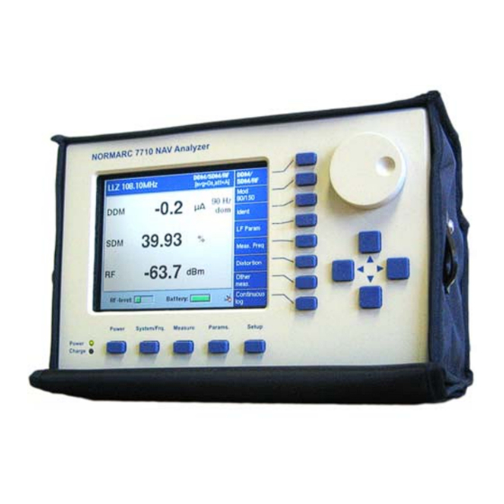
How to operate the instrument Figure 1 The front of the NAV Analyzer... - Page 22 Figure 2 The rear of the NAV Analyzer...
-
Page 23: Using The Pushbuttons And The Wheel
4.1 Using the pushbuttons and the wheel When all external connections are made, the NAV Analyzer is operated through the use of pushbuttons and the adjustment wheel. Below the screen are five menu buttons for selecting the main functionality. The main functionality includes Power on/off, setup and measurements. - Page 24 Figure 3 Example screenshot with sub menu...
-
Page 25: Indicators
4.2 Indicators Power indicator (green LED) ON – instrument on ON and blank screen – screen saver activated Blinking slowly – instrument in Sleep mode Off – instrument off Charge indicator (yellow LED) OFF – no charging Blinking quickly - full charge is pending. Instrument has just been put on charge and is slowly charged until the cell voltage reaches 1V. - Page 26 Red square around text and a full red bar – input level is too high Battery indicator (bottom right parameter on all screens) The battery indicator shows the status of the 12V-level by monitoring the individual battery cells. It is the cell with the lowest voltage that is shown.
-
Page 27: Operating Instructions
Operating instructions 5.1 How to select NAV system type 5.1.1 Manual selection Select the menu button [ System/Frq ] Select the submenu button [ Choose system ] Select LLZ, GP, MKR or VOR Select frequency Optionally Add/Replace/Delete shortcuts 5.1.2 Automatic selection Select the menu button [ System/Frq ] Select [ Scan freq. -
Page 28: Select Using Shortcuts
5.1.3 Select using shortcuts Select the menu button [ System/Frq ] Select the corresponding shortcut button for the NAV system type/frequency you want to look at If there are more shortcuts than there are buttons available, the lower right button is named [ More ]. Select this button to see more shortcuts. -
Page 29: How To Do Measurements
5.2 How to do measurements 5.2.1 Standard measurements If not already done, select the correct operating mode of the instrument (see 5.1) Select the menu button [ Measure ] Select what to measure on the submenu buttons on the right side 5.2.2 Audible ident If not already done, select the correct operating mode of the instrument (see 5.1) The ident signal is available on the audio output connector at the rear side of the instrument... -
Page 30: If Signal
5.2.4 IF signal The IF signal is a translated RF channel signal with carrier frequency of 200kHz. The signal is available at pin 4 on the RS-232 connector (9-pin D-Sub) at the rear of the instrument. This pin is also used for the Baseband signal. -
Page 31: How To Set Up Lowpass Filter For Ddm
One of the submenu buttons is named [ 150Hz dom ] or [ 90Hz dom ], and denotes the dominance algorithm currently defined. If you want to change the setting, press the button and then the button for the desired dominance setting 5.3.3 How to set up lowpass filter for DDM Select the menu button [ Params ] Select the submenu button [ DDM LP... -
Page 32: How To Set The Correct Attenuation
5.3.5 How to set the correct attenuation Select the menu button [ Params ] Select the submenu button [ Atten… ] Select any of the predefined attenuator settings, or select [ Auto ] if you want the instrument itself to determine how much attenuation is needed 5.4 How to do procedure measurements A procedure consists of parameter data sets and marks, all marked with timestamps that are stored in the... -
Page 33: To Define A Procedure
The raw data is being stored. meas: used making spot measurements along the centre line. CrossOver-run samples/sec): When continuous recording of a crossover can be carried out this is the procedure to be used. Predefined marks for different azimuth angles can be used to indicate the position. - Page 34 Select the [ Save sequence ] to store the procedure...
-
Page 35: To Run A Procedure
5.4.2 To run a procedure Select the correct operating mode of the instrument (see 5.1) Select the submenu button [ Other meas. ] Select the wanted procedure Select the [ Start ] – button to start the procedure Insert marks according to the procedure by hitting the [ Store ] – button End the procedure by selecting the [ Stop ] –... -
Page 36: How To Log Data To A File
5.5 How to log data to a file Select the correct operating mode of the instrument (see 5.1) Select [ Measure ] Select [ Continuous log ] Select the [ Interval ] – button to set the interval between each record measured. The number specifies the interval between logging to the log file. -
Page 37: How To Connect To A Computer Through The Network Interface
5.6 How to connect to a computer through the network interface The instrument has a built-in web server that can be accessed through the LAN connector at the back. A connection can either be done directly to a computer or to a computer via a network with DHCP server. When connecting directly to a computer, the NORMARC 7710 may be set up as a DHCP-server, thereby simplifying the connection. -
Page 38: Connecting Directly To A Computer (Win Xp)
5.6.2 Connecting directly to a computer (Win XP) In the browser used for connecting to the instrument, turn off the use of Proxy servers. In IE this can be done by Tools – Internet Options – Connections – LAN Settings... and deselecting the Proxy server box. - Page 39 Disable this option...
- Page 40 Turn on the instrument Connect the instrument to the computer with the crossed network cable Press the [ Setup ] – button Press the [ Network ] – button Check that the instruments IP-address is within the APIPA (Automatic Private IP Addressing) range (169.254.0.0-169.254.255.255).
-
Page 41: Connecting Via Network With Dhcp Server
5.6.3 Connecting via network with DHCP server Turn on the instrument Connect the instrument to the computer with normal network cable (not supplied) Press the [ Setup ] – button Press the [ Network ] – button Press [ Dhcp on ] and then [ Init network ]. -
Page 42: File Management
5.7 File management Press the menu button [ Setup ] Press the submenu button [ File… ] Highlight a file To delete the file, press the submenu button [ Delete ] To view marks set in a file, press the button [ View Marks ] 5.8 How to upgrade the NAV Analyzer software Se section 7.3... -
Page 43: Menu Reference
Menu reference The buttons for selecting the main functions are Located below the screen. Each main function has one menu on the right side of the screen. When the menu commands exceed the number of available menu items, there might be a [ More…... -
Page 44: System Selection And Frequency Setup
6.2 System selection and frequency setup Pressing the System/Frq button below the screen accesses the system selection and frequency setup menu. The menu items are: [ Choose system ] Choose if you want to measure LLZ, GP, MKR or VOR. Subsequently you will be asked for the frequency for the selected system. -
Page 45: Measurements
6.3 Measurements The submenus here depend on what type of signals you have set up (see. 6.2) 6.3.1 When measuring LLZ If you select the Localizer (see. 6.2), by pressing the Measure button below the screen, the LLZ measure menu is accessed. - Page 46 When [ Other meas. ] is pressed you can select the stored procedures for the LLZ system. These procedures may look like the following: [ CL Run ] Centreline run [ CL Meas ] Centreline measurement [ Cross Meas. ] Crossover measurement [ Cross Run ] Crossover run...
- Page 47 Set speed Use this when you will drive the CL run at a fixed speed. Select the speed (km/h) by the use of the wheel or the up/down button before selecting Set speed Use Tachometer Use this option when you have connected a tachometer to the AUX- port on the rear of the NORMARC 7710.
-
Page 48: When Measuring Gp
6.3.2 When measuring GP If you select the Glide Path (see. 6.2), by pressing the Measure button below the screen, the GP measure menu is accessed. The submenus at the right side of the screen are: [ DDM/SDM ] Measure DDM/SDM [ Mod 90/150 ] Measure level of each modulation tone and RF-level [ LF Param ]... - Page 49 When [ Other meas. ] is pressed you can select the stored procedures for the GP system. These procedures may look like the following: [ GP slice ] Same as CL Meas, but data is logged at certain positions on a vertical axis.
-
Page 50: When Measuring Mkr
6.3.3 When measuring MKR If you select the Marker Beacon (see. 6.2), by pressing the Measure button below the screen, the MKR measure menu is accessed. The submenus at the right side of the screen are: [ Mod depth ] Measure modulation depth for 400Hz, 1300Hz and 3000Hz in addition to RF Level [ Meas. -
Page 51: When Measuring Vor
6.3.4 When measuring VOR If you select the VOR (see. 6.2), by pressing the Measure button below the screen, the VOR measure menu is accessed. The submenus at the right side of the screen are: [ FMI/Bearing ] Measure primary parameters FMI and bearing [ Mod depth ] Measure modulation depth for 30Hz and 9960Hz in addition to RF Level. - Page 52 When [ Other meas. ] is pressed you can select the stored procedures for the VOR system. These procedures may look like the following: [ VOR Seq ] Define points in sequence, and run sequence procedure...
-
Page 53: Parameter Setup
6.4 Parameter setup Pressing the Params button below the screen accesses the parameter setup menu. The submenus at the right side of the screen are: [ μA ] [ % DDM ] [ 150Hz dom ] Select whether to calculate SDM as Mod150Hz-Mod90Hz, or as Mod90Hz-Mod150Hz. -
Page 54: System
6.5 System Pressing the Setup button below the screen accesses the system setup menu. The submenus at the right side of the screen are: [ Set ] The actual setting of the date/time set by the up/down/left/right arrows and the wheel. [ File…... -
Page 55: Maintenance, Calibration And Software Updates
Maintenance, calibration and software updates 7.1 Maintenance 7.1.1 Batteries The battery pack is rechargeable. When the batteries are worn out or damaged, they should be replaced. To do this, remove the back cover (see fig) and replace the batteries with equivalent types (NiMH, size D, rechargeable 10.000mAh). - Page 56 Self discharge When NiMH batteries have not been used for a long time they will self-discharge. The voltage on the cells will typically be < 1.0V. To fix this, restart the charge cycle once every five minutes a few times. Turning off and on again the external power restarts the charge cycle.
- Page 57 IMPORTANT NOTE!!! • Do not charge the batteries at high temperatures. This will reduce the life time and capacity of the batteries • Do not charge fully charged batteries. Every time the external power is connected, a new charge cycle will be initiated. If the batteries are never discharged, this repeated new charge cycle will eventually over-charge and damage the batteries.
-
Page 58: Use Of Alkaline Batteries
The battery indicator on the instrument does not display the correct information when using alkaline batteries. Do not charge alkaline batteries! 7.1.5 Corrective maintenance Except for replacement of batteries, Northrop Grumman Park Air Systems should do all corrective maintenance. 7.2 Calibration The instrument as delivered from factory is ready for use. -
Page 59: Software Updates
7.3 Software Updates New functions and enhanced functionality may be added to the instrument by upgrading the software. Information about software versions and how to download them can be found on the company's web page or by sending a request to support at: normarc.support@no.parkairsystems.com The procedure for upgrading the software is as follows. - Page 60 - Page intentionally blank -...
Need help?
Do you have a question about the NORMARC 7710 NAV and is the answer not in the manual?
Questions and answers