Table of Contents
Advertisement
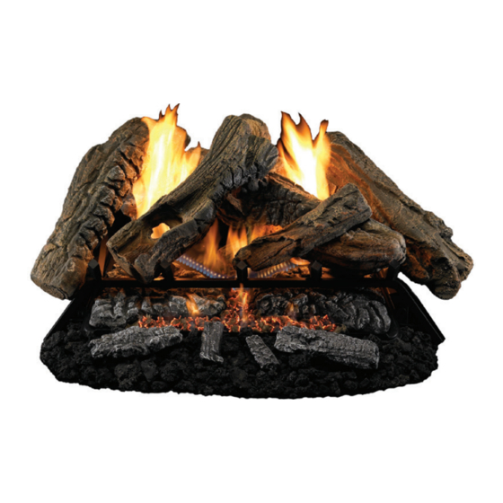
Cedar Ridge
h e a r t h
WARNING: If the information in this manual is not
followed exactly, a fire or explosion may result causing
property damage, personal injury or loss of life.
— Do not store or use gasoline or other flammable va-
pors and liquids in the vicinity of this or any other
appliance.
— WHAT TO DO IF YOU SMELL GAS
• Do not try to light any appliance.
• Do not touch any electrical switch; do not use any
phone in your building.
• Immediately call your gas supplier from a neighbor's
phone. Follow the gas supplier's instructions.
• If you cannot reach your gas supplier, call the fire
department.
— Installation and service must be performed by a quali-
fied installer, service agency or the gas supplier.
WARNING: This appliance is equipped for Natural and
Propane gas. Field conversion is not permitted other than
between natural or propane gases.
Questions, problems, missing parts? Before returning to your retailer, call
our customer service department at 1-866-573-0674, 8:00 am - 4:30 pm CST,
Monday through Friday or email customerservice@usaprocom.com
VENT-FREE GAS LOGS
OWNER'S OPERATION AND
INSTALLATION MANUAL
®
CRHEB24RT AND CRHEB30RT
MODELS
PFS
®
US
Advertisement
Table of Contents

Related Manuals for Cedar Ridge CRHEB24RT


Summary of Contents for Cedar Ridge CRHEB24RT
- Page 1 INSTALLATION MANUAL ® h e a r t h MODELS CRHEB24RT AND CRHEB30RT ® WARNING: If the information in this manual is not followed exactly, a fire or explosion may result causing property damage, personal injury or loss of life.
-
Page 2: Table Of Contents
TABLE OF CONTENTS Safety ............3 Operation ..........21 Specifications ..........5 Inspecting Burners........26 Qualified Installing Agency ......5 Care And Maintenance ......27 Product Features ........5 Troubleshooting ........29 Product Identification ......... 5 Parts ............32 Local Codes..........6 Replacement Parts ........ -
Page 3: Safety
SAFETY CARBON MONOXIDE POISONING: Early WARNING: This appliance is signs of carbon monoxide poisoning resemble for installation only in a solid- the flu, with headaches, dizziness or nausea. If you have these signs, the heater may not fuel burning masonry or UL127 be working properly. - Page 4 SAFETY 8. Do not use heater if any part has been WARNING: The log set be- under water. Immediately call a qualified comes very hot when running. service technician to inspect the room Keep children and adults away heater and to replace any part of the control system and any gas control which from hot surfaces to avoid burns has been under water.
-
Page 5: Specifications
SPECIFICATIONS Models CRHEB24RT and CRHEB30RT Gas Type Natural Gas Propane Gas Ignition Electronic Piezo Ignitor Electronic Piezo Ignitor Input Rating 35,000 Btu/Hr 35,000 Btu/Hr Manifold Pressure 4" W.C. 9" W.C. Inlet Gas Pressure* (inches Maximum 10.5" Maximum 14" of water) (*for purposes of Minimum 5"... -
Page 6: Local Codes
LOCAL CODES Install and use heater with care. Follow all State of Massachusetts: The installation local codes. In the absence of local codes, must be made by a licensed plumber or use the latest edition of The National Fuel gas fitter in the Commonwealth of Mas- Gas Code, ANSI Z223.1/NFPA 54*. -
Page 7: Air For Combustion And Ventilation
AIR FOR COMBUSTION AND VENTILATION heat loss in homes. Home owners weather WARNING: This heater shall strip and caulk around windows and doors not be installed in a confined space to keep the cold air out and the warm air in. or unusually tight construction During heating months, home owners want their homes as airtight as possible. - Page 8 AIR FOR COMBUSTION AND VENTILATION DETERMINING FRESH-AIR FLOW FOR HEATER LOCATION Determining if You Have a Confined or Unconfined Space Use this work sheet to determine if you have 4. Compare the maximum Btu/Hr the space a confined or unconfined space. can support with the actual amount of Btu/ Hr used.
- Page 9 AIR FOR COMBUSTION AND VENTILATION VENTILATION AIR Ventilation Air From Inside Building This fresh air would come from an adjoining 1 and 2, Figure 2). You can also remove door unconfined space. When ventilating to an into adjoining room (see option 3, Figure 2). adjoining unconfined space, you must provide Follow the National Fuel Gas Code, ANSI two permanent openings: one within 12"...
-
Page 10: Installation
INSTALLATION NOTICE: This heater is intended WARNING: Never install the for use as supplemental heat. heater Use this heater along with your • in a bedroom or bathroom primary heating system. Do not • in a recreational vehicle install this heater as your pri- •... - Page 11 INSTALLATION CHECK GAS TYPE Minimum Noncombustible Material Clearances Be sure your gas supply is right for your heat- If Not Using Mantel er. Otherwise, call dealer where you bought Note: If using a mantel, proceed to If Using the heater for proper type heater. Mantel.
- Page 12 INSTALLATION If Using Mantel at least 8" up. If noncombustible material is less than 12", you must install the fireplace You must have noncombustible material(s) hood accessory. Even if noncombustible above the fireplace opening. Noncombustible material is more than 12", you may need the materials (such as slate, marble, tile, etc.) hood accessory to deflect heat away from must be at least 1/2"...
- Page 13 INSTALLATION FLOOR CLEARANCES A. If installing appliance on the floor level, B. If combustible materials are less than 14" you must maintain the minimum distance to the fireplace, you must install appliance of 14" to combustibles (see Figure 8). at least 5" above the combustible flooring (see Figure 9).
- Page 14 INSTALLATION 4. Remove hex plug (with wrench provided) 4. Remove hex plug (with wrench provided) from natural gas inlet of regulator (see from propane/LP gas inlet of regulator Figure 10, page 13). Install hex plug into (see Figure 11). Install hex plug into NG LP inlet of regulator.
- Page 15 INSTALLATION CONNECTING TO GAS SUPPLY WARNING: A qualified ser- CAUTION: For natural gas, vice technician must connect check your gas line pressure heater to gas supply. Follow all before connecting heater to gas local codes. line. Gas line pressure must be no greater than 10.5"...
- Page 16 INSTALLATION Typical Inlet Pipe Diameters Install sediment trap in supply line as shown Use 3/8" black iron pipe or greater. Installa- in Figure 13. Place sediment trap where it is tion must include an equipment shutoff valve, within reach for cleaning. Place sediment trap union, and plugged 1/8"...
- Page 17 INSTALLATION CHECKING GAS CONNECTIONS WARNING: Never use an open WARNING: Test all gas piping flame to check for a leak. Apply and connections, internal and a noncorrosive leak detection external to unit, for leaks after fluid to all joints. If bubbles form, installing or servicing.
- Page 18 INSTALLATION PRESSURE TESTING HEATER GAS CONNECTIONS 1. Open equipment shutoff valve (see Figure 17, page 17). Apply a noncorrosive leak 15, page 17). detection fluid to all joints. Bubbles form- ing show a leak. 2. Open main gas valve located on or near gas meter for natural gas or open pro- 5.
- Page 19 INSTALLATION PLACING EMBER MATERIAL Separate the ember material into light pieces WARNING: Use only ember smaller than the size of a dime. Place the material provided with log set. pieces around the round gas ports starting in Do not add additional ember the front of the burner and working your way toward the back of the burner.
- Page 20 INSTALLATION 3. Insert pin on the back of log #4 into slot IMPORTANT: Make sure logs do not cover in rear log bracket on grate base (see any burner ports. It is very important to install Figures 21 and 22). the logs exactly as instructed.
-
Page 21: Operation
OPERATION FOR YOUR SAFETY READ BEFORE LIGHTING not use any phone in your building. WARNING: If you do not fol- • Immediately call your gas supplier low these instructions exactly, a from a neighbor’s phone. Follow the fire or explosion may result caus- gas supplier’s instructions. - Page 22 OPERATION 9. With control knob pressed in, push 12. Press the LEARN BUTTON on the front of down and release ignitor button. This the remote receiver box until you hear a will light pilot. The pilot is attached to beep (see Programming the Remote and the rear of the burner.
- Page 23 OPERATION REMOTE CONTROL SYSTEM Install Batteries 2. Place the slide switch on the receiver in Batteries are required in both the Remote the remote position (see Figure 28). Control (Transmitter) (2 AAA size) and Re- 3. Use a pen or small screwdriver to gently ceiver (4 AA size) (see Figure 27).
- Page 24 OPERATION REMOTE CONTROL OPERATION Setting°F/°C Scale This appliance must not be used with glass The factory setting for temperature is °F. To doors in the closed position. This can lead to pilot outages and severe sooting outside change this setting to°C, press the ON key the fireplace.
- Page 25 OPERATION THERMOSTAT FUNCTION REMOTE CONTROL OPERATION NOTES Setting Desired Room Temperature The Thermo Feature on the transmitter op- The remote control system can control the erates the appliance whenever the ROOM thermostat when the transmitter is in the TEMPERATURE varies a certain number of THERMO mode.
-
Page 26: Inspecting Burners
INSPECTING BURNERS IMPORTANT: Owner’s should check pilot flame pattern and burner flame pattern often. Incorrect flame patterns indicate the need for cleaning (see Care and Maintenance, page 27) or service. WARNING: Only a qualified service person should service and repair heater. This includes maintenance requiring replacement or alteration of components. -
Page 27: Care And Maintenance
CARE AND MAINTENANCE WARNING: Turn off heater and let cool before servicing. CAUTION: You must keep control areas, burner, and circulating air passageways of heater clean. Inspect these areas of heater before each use. Have heater inspected yearly by a qualified service techni- cian. - Page 28 CARE AND MAINTENANCE ODS/PILOT Natural Gas Use a vacuum cleaner, pressurized air, or a Burner small, soft bristled brush to clean. A yellow tip on the pilot flame indicates dust Propane/LP and dirt in the pilot assembly. There is a small Gas Burner pilot air inlet hole about 2"...
-
Page 29: Troubleshooting
TROUBLESHOOTING WARNING: If you smell gas: • Shut off gas supply. • Do not try to light any appliance. • Do not touch any electrical switch; do not use any phone in your building. • Immediately call your gas supplier from a neighbor’s phone. Fol- low the gas supplier’s instructions. - Page 30 TROUBLESHOOTING Problem Possible Cause Corrective Action ODS/pilot lights but flame 1. Control knob is not fully 1. Press in control knob fully. goes out when control pressed in. knob is released. 2. Control knob is not pressed 2. After ODS/pilot lights, keep in long enough.
- Page 31 TROUBLESHOOTING Problem Possible Cause Corrective Action Slight smoke or odor 1. Residues from manufactur- 1. Problem will stop after a few during initial operation. ing process. hours of operation. Heater produces a whis- 1. Turning control knob to high 1. Turn control knob to low tling noise when burner position when burner is cold.
-
Page 32: Parts
PARTS MODELS CRHEB24RT AND CRHEB30RT 13-3 13-2 13-1 13-4 13-7 13-6 13-5 (30" Models) 13-5 (24" Models) 13-9 13-10 13-8 (30" Models) 13-12 13-11 13-8 13-13 (24" Models) TEMP www.usaprocom.com 200015-01B... - Page 33 PARTS MODELS CRHEB24RT AND CRHEB30RT This list contains replaceable parts for your heater. When ordering replacement parts, follow the instructions listed under Replacement Parts on page 34 of this manual. PART # ITEM CRHEB24RT CRHEB30RT DESCRIPTION 24ED102B-01 24ED102B-01 Grate Assembly...
-
Page 34: Replacement Parts
REPLACEMENT PARTS Note: Use only original replacement parts. This will protect your warranty coverage for parts replaced under warranty. PARTS UNDER WARRANTY Contact authorized dealers of this product. • Model and serial number of your heater If they can’t supply original replacement •... -
Page 35: Service Hints
SERVICE HINTS When Gas Pressure Is Too Low • pilot will not stay lit • burners will have delayed ignition • fireplace will not produce specified heat • propane/LP gas supply might be low (propane/LP units only) You may feel your gas pressure is too low. If so, contact your local gas supplier. TECHNICAL SERVICE You may have further questions about installation, operation, or troubleshooting. -
Page 36: Warranty
WARRANTY KEEP THIS WARRANTY Model _______________________________ Serial No. ____________________________ Date Purchased _______________________ Keep receipt for warranty verification. REGISTER YOUR PRODUCT AT WWW.USAPROCOM.COM IMPORTANT: We urge you to register your product within 10 days of date of installation, complete with entire serial number which can be found on the rating plate. Please fill out the warranty infor- mation above for your personal records.
Need help?
Do you have a question about the CRHEB24RT and is the answer not in the manual?
Questions and answers
How to assemble logs
To assemble the logs for the Cedar Ridge CRHEB24RT:
1. Insert the pin on the back of Log #4 into the slot in the rear log bracket on the grate base.
2. Insert the pin on the bottom of Log #5 into the hole in Log #4, with the other end resting on the grate base.
3. Insert the pin on the bottom of Log #6 into the hole in Log #4, with the other end resting on the grate base.
4. Insert the pin on the bottom of Log #7 into the hole in Log #4, with the other end resting on the grate base.
5. Insert the pin on the bottom of Log #8 into the hole in Log #3, and rest its front edge onto Log #4.
6. Turn Log #9 as shown in the referenced figure (not provided).
Important: Do not cover any burner ports and use only the logs supplied with the heater. Follow the instructions exactly.
This answer is automatically generated
how do you remove the old batterie from the igniter?