Table of Contents
Advertisement
Cedar Ridge
h e a r t h
WARNING: This appliance
is equipped for (Natural and
Propane) gas. Field conversion is
not permitted other than between
natural or propane gases.
WARNING: IF THE INFORMATION IN THIS MANUAL IS NOT FOLLOWED
EXACTLY, A FIRE OR EXPLOSION MAY RESULT CAUSING PROPERTY
DAMAGE, PERSONAL INJURY, OR LOSS OF LIFE.
– Do not store or use gasoline or other flammable vapors and liquids in vicinity of this or any
other appliance.
WHAT TO DO IF YOU SMELL GAS
•
Do not try to light any appliance.
•
Do not touch any electrical switch; do not use any phone in your building.
•
Immediately call your gas supplier from a neighbor's phone. Follow the gas
supplier's instructions.
•
If you cannot reach your gas supplier, call the fire department.
– Installation and service must be performed by a qualified installer, service agency
or the gas supplier.
This is an unvented gas-fired heater. It uses air (oxygen) from the room in which it is
installed. Provisions for adequate combustion and ventilation air must be provided.
Refer to Air For Combustion and Ventilation section on page 8 of this manual.
INSTALLER: Leave this manual with the appliance. CONSUMER: Retain this manual
for future reference.
This appliance may be installed in an aftermarket, permanently located manufactured
(mobile) home, where not prohibited by local codes. This appliance is only for use
with propane or natural gas. This appliance is equipped with a simple means to
switch between propane and natural gas. Field conversion by any other means
including the use of a kit is not permitted
Questions, problems, missing parts? Before returning to your retailer, contact
our customer service department at 1-866-573-0674, 8:00 a.m - 4:30 p.m.,
EST, Monday - Friday or e-mail customerservice@usaprocom.com.
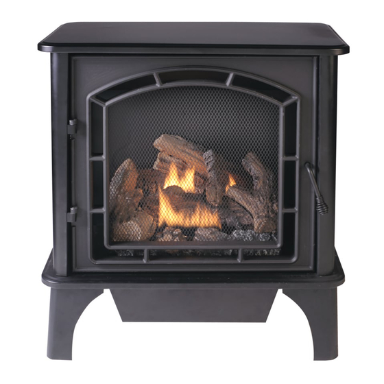
VENT-FREE GAS STOVE
®
CAUTION - FOR YOUR SAFETY
ITEM #0328253
MODEL #CRHSD25RT
Español p. 35
LS-SSSD25RT-1103
Advertisement
Table of Contents

Subscribe to Our Youtube Channel
Related Manuals for Cedar Ridge CRHSD25RT


Summary of Contents for Cedar Ridge CRHSD25RT
- Page 1 ITEM #0328253 VENT-FREE GAS STOVE Cedar Ridge MODEL #CRHSD25RT ® h e a r t h Español p. 35 WARNING: This appliance is equipped for (Natural and Propane) gas. Field conversion is not permitted other than between natural or propane gases.
-
Page 2: Table Of Contents
TABLE OF CONTENTS Safety Information..........................3 Product Features..........................6 Air For Combustion and Ventilation....................8 Installation ............................11 Installing Logs..........................18 Operation............................19 Care and Maintenance........................26 Troubleshooting..........................28 Replacement Parts..........................31 WARNING: Read the installation & operation instructions before using this appliance. IMPORTANT: Read instructions and warnings carefully before starting installation. Failure to follow these instructions may result in a possible fire hazard and will void the warranty. -
Page 3: Safety Information
SAFETY INFORMATION IMPORTANT: Read this owner’s manual carefully and completely before trying to assemble, operate, or service this heater. Improper use of this heater can cause serious injury or death from burns, fire, explosion, electrical shock, and carbon monoxide poisoning. Only a qualified installer, service agent, or local gas supplier may install and service this product. - Page 4 Do not place Propane/LP supply tank(s) inside any structure. Propane/LP supply tank(s) must be placed outdoors. This heater needs fresh air ventilation to run properly. This heater has an Oxygen Depletion Sensing (ODS) safety shut-off system. The ODS shuts down the heater if not enough fresh air is available.
- Page 5 Do not add extra logs or ornaments such as pine cones, vermiculite, or rock wool. Using these added items can cause sooting. Do not add lava rock around base. Rock and debris could fall into the control area of heater. This heater is designed to be smokeless.
-
Page 6: Product Features
PRODUCT FEATURES SAFETY PILOT This heater has a pilot with an Oxygen Depletion Sensing (ODS) safety shutoff system. The ODS/pilot shuts off the heater if there is not enough fresh air. PIEZO IGNITION SYSTEM This heater is equipped with an electronic piezo control system. This system requires AAA batteries (provided). - Page 7 UNPACKING 1. Remove top inner pack. 2. Tilt carton so that heater is upright. 3. Remove protective side packaging. 4. Slide heater out of carton. 5. Remove protective plastic wrap. 6. Hold the screen, lift, and pull forward. 7. Remove log set by cutting plastic ties. 8.
-
Page 8: Air For Combustion And Ventilation
AIR FOR COMBUSTION AND VENTILATION WARNING: If the area in which the heater may be operated does not meet the required volume for indoor combustion air, combustion and ventilation air shall be provided by one of the methods described in the National Fuel Gas Code, ANSI Z223.1/NFPA 54, the International Fuel Gas Code, or applicable local codes. - Page 9 DETERMINING FRESH-AIR FLOW FOR HEATER LOCATION Determining if You Have a Confined or Unconfined Space Use this worksheet to determine if you have a confined or unconfined space. Space: Includes the room in which you will install heater plus any adjoining rooms with door-less passageways or ventilation grills between the rooms.
- Page 10 WARNING: If the area in which the heater may be operated does not meet the required volume for indoor combustion air, combustion and ventilation air shall be provided by one of the methods described in the NATIONAL FUEL GAS CODE, ANSI Z223.1/NFPA 54, the INTERNATIONAL FUEL GAS CODE, or applicable local codes.
-
Page 11: Installation
INSTALLATION NOTICE: This heater is intended for use as supplemental heat. Use this heater along with your primary heating system. Do not install this heater as your primary heat source. If you have a central heating system, you may run system’s circulating blower while using heater. - Page 12 CONNECTING TO GAS SUPPLY WARNING: A qualified technician must connect heater to gas supply. Follow all local codes. WARNING: This appliance requires a 3/8 in. NPT inlet connection to pressure regulator (see Fig. 5). CAUTION: Never connect heater directly to the gas supply. This heater requires an external regulator (not supplied).
- Page 13 CAUTION: Use only new black iron or steel pipe. Internally tinned copper tubing may be used in certain areas. Check your local codes. Use pipe of ½ in. diameter or greater to allow proper volume gas to heater. If pipe is too small, loss of pressure will occur.
- Page 14 CAUTION: Two gas line installations at the same time are prohibited. The access plate to the simple switching means shall not be opened while the heater is in operation. This appliance can be used with propane or natural gas. It is shipped from the factory adjusted for use with propane.
- Page 15 Fig. 8 Plug Plug Fig. 9 Plug Propane Gas Natural Gas Fig. 10 Plug Propane Gas Natural Gas...
- Page 16 CHECKING GAS CONNECTIONS WARNING: Test all gas piping and connections for leaks after installing or servicing. Correct all leaks immediately. WARNING: Never use an open flame to check for a leak. Apply a mixture of liquid soap and water to all joints. If bubbles form, there may be a leak. Correct all leaks immediately. Pressure Testing Gas Supply Piping System Test Pressures In Excess Of 1/2 PSIG ( 3.5kPa ) 1.
- Page 17 Installation for Remote Receiver: The remote receiver operates on four 1.5V AA-size batteries (included). It is recommended that ALKALINE batteries be used for longer battery life and maximum microprocessor performance. IMPORTANT: New or fully charged batteries are essential for proper operation of the remote receiver as the solenoid power consumption is higher than standard remote control systems.
-
Page 18: Installing Logs
INSTALLING LOGS Fig. 15 - Installing Log Set WARNING: Failure to position the parts in accordance with these diagrams or failure Log Set Burner Ports to use only parts specifically approved with this heater may result in property damage or personal injury. CAUTION: After installation, and periodically thereafter, check to ensure that no flame comes in contact with any log. -
Page 19: Operation
OPERATION FOR YOUR SAFETY READ BEFORE LIGHTING WARNING: If you do not follow these instructions exactly, a fire or explosion may result causing property damage, personal injury, or loss of life. NOTICE: During initial operation of new heater, burning logs will give off a paper burning smell. - Page 20 LIGHTING INSTRUCTIONS 1. STOP! Read the safety information on the front and back of the warning plate on page 19. 2. Make sure manual shutoff valve is fully open. 3. Unscrew ignitor cap and install an AAA type battery with the anode (+) pointing out. Replace cap.
- Page 21 REMOTE CONTROL OPERATION MATCHING SECURITY CODES When matching security codes, be sure slide button on the receiver is in the REMOTE position. To program the remote receiver to LEARN a new security code, press and release the LEARN button on the top of the remote receiver, and then press ON or OFF button on the transmitter. A change in the beeping pattern at the receiver, indicates the transmitter's code has been programmed into the receiver.
- Page 22 SETTING°F/°C SCALE Fig. 20 The factory setting for temperature is °F. To change this setting to°C . First Press the ON key and the OFF key on the transmitter at the same time this will change from°F to °C. Follow this same procedure to change from°C back to°F.
- Page 23 TO CHANGE THE SET TEMPERATURE Press and hold the SET key until the desired set Fig. 26 temperature is reached. (By pressing and holding the set key the LCD screen set numbers will increase from 45° to 99° then restart over at 45°). Next release the SET key.
- Page 24 SETTING UP & USING YOUR REMOTE CONTROL SYSTEM Notice: This guide is intended to provide supplemental information about setting up and using the remote control that was included with your gas logs. It is not intended to replace the information in the Owners Manual. Please refer to the Owners Manual for detailed information about your appliance.
- Page 25 INSPECTING BURNERS Check pilot flame pattern and burner flame patterns often. PILOT FLAME PATTERN 1. Turn control knob to pilot position. 2. Inspect pilot flame and refer to Fig. 32 and 33. • Fig. 32 shows a correct pilot flame pattern. •...
-
Page 26: Care And Maintenance
CARE AND MAINTENANCE WARNING: Failure to keep primary air openings of burners clean may result in sooting and property damage. CAUTION: You must keep control areas, burner, and circulating air passageways of heater clean. Inspect these areas of heater before each use. Have heater inspected yearly by a qualified service person. - Page 27 CLEANING ODS/PILOT Use a vacuum cleaner, pressurized air, or a small, soft bristled brush to clean. A yellow tip on the pilot flame indicates dust and dirt in the pilot assembly. There is a small pilot air inlet hole about two inches from where the pilot flame comes out of the pilot assembly (see Fig.
-
Page 28: Troubleshooting
TROUBLESHOOTING WARNING: If you smell gas: • Shut off gas supply. • Do not try to light any appliance. • Do not touch any electrical switch; do not use any phone in your building. • Immediately call your gas supplier from a neighbor’s phone. Follow the gas supplier’s instructions. - Page 29 Problem Possible Cause Corrective Action ODS/pilot lights but flame 1. Control knob is not fully 1. Press in control knob fully. goes out when control knob pressed in. is released. 2. Control knob is not pressed 2. After ODS/pilot lights, keep in long enough.
- Page 30 Problem Possible Cause Corrective Action Slight smoke or odor 1. Residues from 1. Problem will stop after a during initial operation. Manufacturing process. few hours of operation. Heater produces a 1. Turning control knob to high 1. Turn control knob to low (1) whistling noise when (5) position when burner is position and let warm up for...
-
Page 31: Replacement Parts
REPLACEMENT PARTS NOTE: Use only original replacement parts. This will protect your warranty coverage for parts replaced under warranty. PARTS UNDER WARRANTY Call Customer Service toll free at (1-866-573-0674) for referral information. When calling Customer Service, have ready: • Your name •... - Page 32 REPLACEMENT PARTS LIST For replacement parts, call our customer service department at 1-866-573-0674, 8:00 a.m - 4:30 p.m., EST, Monday - Friday or e-mail customerservice@usaprocom.com. Part.. Description Part # DF ODS NDD0308-400 Fuel Selection Device Assembly YDF06-BD23T Fuel Selection Device Knob MDL304B AF Remote Valve AF-1110...
- Page 34 2-YEAR LIMITED WARRANTY The manufacturer warrants this product to be free from defects in workmanship and material present at time of shipment from the factory for two (2) years from the date of purchase. This warranty applies only to the original purchaser. The manufacturer agrees to correct such defect at no charge or, at our option, replace the product with a comparable or superior model.
Need help?
Do you have a question about the CRHSD25RT and is the answer not in the manual?
Questions and answers