Table of Contents
Advertisement
Cedar Ridge
h e a r t h
WARNING: If the information in this manual is not
followed exactly, a fire or explosion may result causing
property damage, personal injury or loss of life.
— Do not store or use gasoline or other flammable va-
pors and liquids in the vicinity of this or any other
appliance.
— WHAT TO DO IF YOU SMELL GAS
• Do not try to light any appliance.
• Do not touch any electrical switch; do not use any
phone in your building.
• Immediately call your gas supplier from a neighbor's
phone. Follow the gas supplier's instructions.
• If you cannot reach your gas supplier, call the fire
department.
— Installation and service must be performed by a quali-
fied installer, service agency or the gas supplier.
WARNING: This appliance is equipped for Natural and
Propane gas. Field conversion is not permitted other than
between natural or propane gases.
Questions, problems, missing parts? Before returning to your retailer, call
our customer service department at 1-866-573-0674, 7:30 am - 4:15 pm CST,
Monday through Friday or email customerservice@usaprocom.com
VENT-FREE GAS STOVE
OWNER'S OPERATION
®
AND INSTALLATION
CRHQD250TA
PFS
MANUAL
MODEL
®
US
Advertisement
Table of Contents

Related Manuals for Cedar Ridge CRHQD250TA


Summary of Contents for Cedar Ridge CRHQD250TA
- Page 1 VENT-FREE GAS STOVE Cedar Ridge OWNER’S OPERATION ® AND INSTALLATION h e a r t h MANUAL MODEL CRHQD250TA ® WARNING: If the information in this manual is not followed exactly, a fire or explosion may result causing property damage, personal injury or loss of life.
-
Page 2: Table Of Contents
TABLE OF CONTENTS Safety ............3 Operation ..........17 Specifications ..........4 Inspecting Burners........19 Qualified Installing Agency ......5 Care And Maintenance ......20 Product Features ........5 Troubleshooting ........22 Local Codes..........5 Accessories ..........25 Product Identification ......... 6 Service Hints ........... -
Page 3: Safety
SAFETY IMPORTANT: Read this owner’s WARNING: Any change to manual carefully and completely this heater or its controls can before trying to assemble, op- be dangerous. erate, or service this heater. Improper use of this heater can WARNING: Do not allow fans cause serious injury or death to blow directly into fireplace. -
Page 4: Specifications
(dime-size or larger). 9. Turn off and unplug heater and let cool before servicing. Only a qualified service person should service and repair heater. SPECIFICATIONS Model CRHQD250TA Gas Type Natural Gas Propane Gas Maximum Input Rating 25,000 Btu/Hr 25,000 Btu/Hr... -
Page 5: Qualified Installing Agency
QUALIFIED INSTALLING AGENCY Only a qualified agency should install and a) Installing, testing, or replacing gas piping replace gas piping, gas utilization equipment or accessories, and repair and equipment ser- b) Connecting, installing, testing, repairing, vicing. The term “qualified agency” means any or servicing equipment;... -
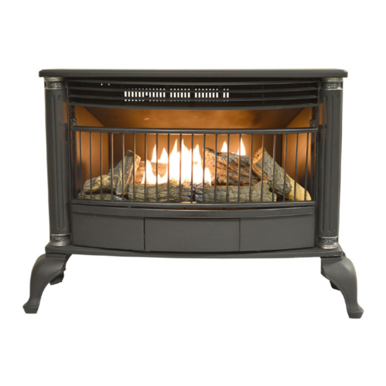
Page 6: Product Identification
PRODUCT IDENTIFICATION Screen Logs Heater Controls (Inside Panel) Figure 1 - Vent-Free Stove UNPACKING Screws 1. Remove top inner pack. 2. Tilt carton so that heater is upright. 3. Remove protective side packaging. 4. Slide heater out of carton. 5. Remove protective plastic wrap. 6. -
Page 7: Air For Combustion And Ventilation
AIR FOR COMBUSTION AND VENTILATION WARNING: This heater shall WARNING: If the area in which not be installed in a confined the heater may be operated does space or unusually tight con- not meet the required volume for struction unless provisions are indoor combustion air, combus- provided for adequate combus- tion and ventilation air shall be... -
Page 8: Installation
AIR FOR COMBUSTION AND VENTILATION Ventilation Air From Outdoors Provide extra fresh air by using ventilation grills or ducts. You must provide two perma- Ventilated Outlet nent openings: one within 12" of the ceiling Attic and one within 12" of the floor. Connect these Outlet items directly to the outdoors or spaces open To Attic... - Page 9 INSTALLATION Minimum Wall and Ceiling IMPORTANT: Vent-free heaters add moisture Clearances to the air. Although this is beneficial, installing heater in rooms without enough ventilation air A. Clearances from outermost point of heater may cause mildew to form too much moisture. to any combustible side wall should not be See Air for Combustion and Ventilation, pages less than 12".
- Page 10 INSTALLATION GAS SELECTION This appliance is factory preset for propane/LP gas. Natural Gas Shown 3-3.5" WC 8-11" WC WARNING: Make sure Regulator Cap is in the appropriate position ADVERTENCIA: Asegúrese la tapa del regulador esté en la posición adecuada, Correct Pilot Flame Pattern as shown in diagrams.
- Page 11 INSTALLATION 2. Apply thread sealant to the threads on a Use only the cap supplied on the 3/8" NPT brass connection fitting. While regulator. Do not use an off the pushing in, rotate the fitting clockwise until shelf pipe plug. This can damage the threads engage the regulator.
- Page 12 INSTALLATION CONNECTING TO GAS SUPPLY WARNING: A qualified ser- CAUTION: For natural gas, vice technician must connect check your gas line pressure heater to gas supply. Follow all before connecting heater to gas local codes. line. Gas line pressure must be no greater than 9.5"...
- Page 13 INSTALLATION Apply pipe joint sealant lightly to male threads. WARNING: Test all gas piping This will prevent excess sealant from going and connections for leaks after into pipe. Excess sealant in pipe could result in clogged heater valves. installing or servicing. Correct For propane/LP installations, the installer must all leaks at once (see page 14).
- Page 14 INSTALLATION CHECKING GAS CONNECTIONS WARNING: Never use an open WARNING: Test all gas piping flame to check for a leak. Apply and connections for leaks after a noncorrosive leak detection installing or servicing. Correct fluid to all joints. If bubbles form, all leaks at once.
- Page 15 INSTALLATION PRESSURE TESTING HEATER GAS CONNECTIONS 1. Open equipment shutoff valve (see Figure 14, page 14). Apply a noncorrosive leak 12, page 14). detection fluid to all joints. Bubbles form- ing show a leak. 2. Open main gas valve located on or near gas meter for natural gas or open pro- 5.
- Page 16 INSTALLATION INSTALLING LOGS Use only logs supplied with heater. Each WARNING: Failure to posi- log is marked with a number. This number tion the parts in accordance will help you to identify the logs when with these diagrams or failure installing.
-
Page 17: Operation
OPERATION FOR YOUR SAFETY READ BEFORE LIGHTING not use any phone in your building. WARNING: If you do not fol- • Immediately call your gas supplier low these instructions exactly, a from a neighbor’s phone. Follow the fire or explosion may result caus- gas supplier’s instructions. - Page 18 OPERATION Note: If pilot does not stay lit, refer to CAUTION: Do not try to ad- Troubleshooting, page 22. Also contact a just heating levels by using the qualified service technician or gas supplier for repairs. Until repairs are made, light equipment shutoff valve.
-
Page 19: Inspecting Burners
INSPECTING BURNERS IMPORTANT: Owner’s should check pilot flame pattern and burner flame pattern often. Incorrect flame patterns indicate the need for cleaning (see Care and Maintenance, page 20 or service. WARNING: Only a qualified service person should service and repair heater. This includes maintenance requiring replacement or alteration of components. -
Page 20: Care And Maintenance
CARE AND MAINTENANCE WARNING: Turn off heater and let cool before servicing. CAUTION: You must keep control areas, burner, and circulating air passageways of heater clean. Inspect these areas of heater before each use. Have heater inspected yearly by a qualified service techni- cian. - Page 21 CARE AND MAINTENANCE ODS/PILOT Use a vacuum cleaner, pressurized air, or a Ignitor Natural Gas Thermocouple small, soft bristled brush to clean. Electrode Burner A yellow tip on the pilot flame indicates dust Propane/LP Gas Burner and dirt in the pilot assembly. There is a small pilot air inlet hole about 2"...
-
Page 22: Troubleshooting
TROUBLESHOOTING WARNING: If you smell gas: • Shut off gas supply. • Do not try to light any appliance. • Do not touch any electrical switch; do not use any phone in your building. • Immediately call your gas supplier from a neighbor’s phone. Fol- low the gas supplier’s instructions. - Page 23 TROUBLESHOOTING Problem Possible Cause Corrective Action When ignitor button is 1. Ignitor electrode is posi- 1. Replace electrode. pressed in, there is no tioned wrong. Ignitor elec- spark at ODS/pilot trode is broken. 2. Ignitor electrode is not con- 2. Replace ignitor cable nected to ignitor cable.
- Page 24 TROUBLESHOOTING Problem Possible Cause Corrective Action Burner(s) does not light 1. Burner orifice is clogged. 1. Clean burner orifice (see after ODS/pilot is lit Care and Maintenance, page 20). 2. Inlet gas pressure is too low. 2. Contact local gas supplier. Delayed ignition of 1.
-
Page 25: Accessories
TROUBLESHOOTING Problem Possible Cause Corrective Action White powder residue 1. When heated, the vapors 1. Turn heater off when using forming within burner from furniture polish, wax, furniture polish, wax, carpet box or on adjacent walls carpet cleaners, etc., turn cleaner or similar products. -
Page 26: Parts
PARTS MODEL CRHQD250TA www.usaprocom.com 200124-01D... -
Page 27: Replacement Parts
PARTS MODEL CRHQD250TA This list contains replaceable parts for your heater. When ordering replacement parts, follow the instructions listed under Replacement Parts of this manual. Item Part # Description BL016-07-02 Blower Mount Panel SL005-01 Blower Bracket QDB29100B Screen QD250T106 Door... -
Page 28: Warranty
WARRANTY KEEP THIS WARRANTY Model _______________________________ Serial No. ____________________________ Date Purchased _______________________ Keep receipt for warranty verification. REGISTER YOUR PRODUCT AT WWW.USAPROCOM.COM IMPORTANT: We urge you to register your product within 10 days of date of installation, complete with entire serial number which can be found on the rating plate. Please fill out the warranty infor- mation above for your personal records.
Need help?
Do you have a question about the CRHQD250TA and is the answer not in the manual?
Questions and answers
The stove will not shut off How do I set the thermostat?
The thermostat on the Cedar Ridge CRHQD250TA stove senses the room temperature and adjusts the burner accordingly. You can set the control knob to any comfort level between Low (1) and High (5). The burner will turn off when the room exceeds the set temperature and cycle back on when the temperature drops below the setting.
This answer is automatically generated