Table of Contents
Advertisement
Quick Links
HIGH SPEED BURNISHER
Operating Instructions (ENG)
Instrucciones de Funcionamiento (SPA)
Bedienungsanleitung (GER)
Istruzioni operative (ITA)
MODELS:
MB2000I
Read these instructions before using the machine
Lea las instrucciones antes de utilizar la máquina
Bitte lesen Sie diese Anleitungen, bevor Sie die Maschine in Gebrauch nehmen
Leggere attentamente le presenti istruzioni prima di azionare la macchina
B
980071 01/29/03
Advertisement
Table of Contents

Related Manuals for Windsor MERiT 2000


Summary of Contents for Windsor MERiT 2000
- Page 1 HIGH SPEED BURNISHER Operating Instructions (ENG) Instrucciones de Funcionamiento (SPA) Bedienungsanleitung (GER) Istruzioni operative (ITA) MODELS: MB2000I Read these instructions before using the machine Lea las instrucciones antes de utilizar la máquina Bitte lesen Sie diese Anleitungen, bevor Sie die Maschine in Gebrauch nehmen Leggere attentamente le presenti istruzioni prima di azionare la macchina 980071 01/29/03...
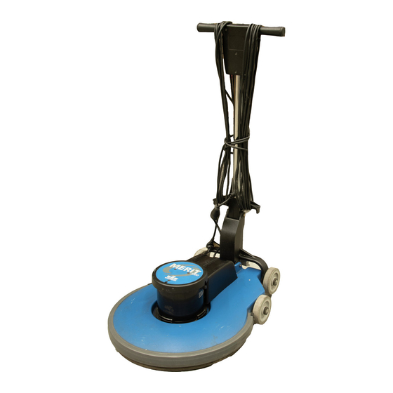
- Page 2 MACHINE DATA LOG/OVERVIEW MODEL______________________________ DATE OF PURCHASE ________________ SERIAL NUMBER____________________ YOUR DEALER Name: __________________________________________________________________________________________________ Address: _______________________________________________________________________________________________ Phone Number: _________________________________________________________________________________________ OVERVIEW The MB2000I is a mains powered, portable floor burnisher intended for commercial use. The appliance can be fitted with a variety of pads to perform various floor care functions. The appliance employs active dust control, and automatically adjusted pad pressure.
-
Page 3: Table Of Contents
TABLE OF CONTENTS Machine Data Log/Overview......2 Table of Contents ...........3 HOW TO USE THIS MANUAL How to use this Manual........1-1 SAFETY Important Safety Instructions......2-1 Hazard Intensity Level........2-2 Grounding Instructions........2-3 OPERATION Technical Specifications ........3-1 Handle Installation..........3-2 Operation............3-3 Pad Driver Installation........3-3 MAINTENANCE Machine Troubleshooting.......4-1 Wiring Diagram/Notes ........4-2... -
Page 4: How To Use This Manual
SERIAL NO. FROM – column indicates Parts may be ordered from authorized Windsor the first machine the part number is dealers. When placing an order for parts, the applicable to. When the machine design... -
Page 5: Important Safety Instructions
IMPORTANT SAFETY INSTRUCTIONS When using an electrical appliance, basic precaution must always be followed, including the following: READ ALL INSTRUCTIONS BEFORE USING THIS MACHINE. WARNING: To reduce the risk of fire, electric shock, or injury: Use only indoors. Do not use outdoors or expose to rain. Use only as described in this manual. -
Page 6: Hazard Intensity Level
Unless Operation Guide is Read and understood. In Flammable or Explosive areas. In areas with possible falling objects. WHEN SERVICING MACHINE: Avoid moving parts. Do not wear loose clothing; jackets, shirts, or sleeves when working on the machine. Use Windsor approved replacement parts. MB2000I 980071 11/15/02... -
Page 7: Grounding Instructions
GROUNDING INSTRUCTIONS THIS PRODUCT IS FOR COMMERCIAL USE ONLY. ELECTRICAL: The amp, hertz, and voltage are listed on the data label found on each machine. Using voltages above or below those indicated on the data label will cause serious damage to the motors. -
Page 8: Technical Specifications
TECHNICAL SPECIFICATIONS ITEM DIMENSION/CAPACITY Construction Heavy-duty die cast aluminum deck with heavy-duty rubber bumper, tubular steel self adjusting handle with die cast aluminum handle housing. Motor 1.75 hp Transmission Direct drive from motor shaft. Pad speed 2000 rpm Electrical system 230 volts, 50Hz Cable 75’... -
Page 9: Handle Installation
HANDLE INSTALLATION HANDLE ASSEMBLY HANDLE MOUNT BRACKET DECK ASSEMBLY 3. Install Handle Assembly as shown. The machine is shipped with handle unassembled. 4. Slide Bolt (item 3) thru, washers (item 2), Handle Follow these steps for installation: Mount Brackets and Handle Assembly (38314) as shown. -
Page 10: Operation
OPERATION CONTROLS 6. To stop the machine, release the switch levers. 7. Do not let machine rest on pad. When finished 1. Safety Lock – Prevents unintended operation of with the machine, return handle to the storage the machine. position. 2. -
Page 11: Machine Troubleshooting
MACHINE TROUBLESHOOTING PROBLEM CAUSE SOLUTION Circuit breaker tripped in Check and reset building. Power switch failure Test switch for continuity and replace if necessary. Tripped circuit breaker Reset Faulty power cord Replace Machine will not run Fuse in motor is blown Replace CAUTION: To reduce the risk of electrical shock,... -
Page 12: Wiring Diagram/Notes
WIRING DIAGRAM/NOTES NOTES: MB2000I 980071 01/29/03... - Page 13 THIS PAGE LEFT BLANK INTENTIONALLY MB2000I 980071 11/15/02...
-
Page 14: Deck Group
DECK GROUP MB2000I 980071 11/15/02... - Page 15 DECK GROUP SERIAL NO. PART NO. DESCRIPTION NOTES: FROM 53805 MOTOR, 230 VOLT 1.5HP 2000RPM 27918 COVER, FILTER BAG 140441 BAG, DUST (PACKAGE OF 10 BAGS) 05156 AXLE, FRONT 87203 WASHER, 14MM ID X 36 MM OD 87054 WASHER, M8 FLAT DIN125A PLT 70262 SCR, M8 X 20 HHMS PLTD 70691...
-
Page 16: Handle Group
HANDLE GROUP MB2000I 980071 11/15/02... - Page 17 HANDLE GROUP SERIAL NO. PART NO. DESCRIPTION NOTES: FROM 70686 SCR, M6 X 45 SHCS BLK 51326 LOCK, SAFETY HANDLE 73990 SPRING, EXT. .5OD X 3.5L 140428 BAR, HANDLE 36196 GRIP, POLISHER HANDLE 51327 LEVER, SWITCH 57274 NUT, M6 X 1 500194 LABEL, WARNING 41363...
-
Page 18: Lower Handle Group
LOWER HANDLE GROUP SEE NOTE NOTE: GREASE ITEMS 14 AND SLIDE AREA OF 19 AS NECESSARY WHEN SERVICING. NOTA: ENGRASE LOS ELEMENTOS MARCADOS CON EL NÚMERO 14 Y EL ÁREA DE DESLIZAMIENTO NÚMERO 19 SI ES NECESARIO CUANDO LE REALICE EL SERVICIO A LA MÁQUINA. - Page 19 LOWER HANDLE GROUP SERIAL PART NO. DESCRIPTION NOTES: FROM 70738 SCR, M5 X .8MM X 10 MM PPHMS BLK 20005 CLAMP, 5/16 NYLON 67468 RING, 10MM EXTERNAL SNAP 66340 PIN, DOWEL 10MM DIA X 124 MM LG 140421 BRACKET, HANDLE LINK 67469 RING, 13MM EXTERNAL SNAP 87234...
-
Page 20: Motor Group
MOTOR GROUP MB2000I 980071 11/15/02... - Page 21 MOTOR GROUP SERIAL NO. PART NO. DESCRIPTION NOTES: FROM 500421 LABEL, MB2000 MAIN 70702 SCR, M5 X .8 X15MM BLK 27884 COVER, MOTOR 1.25HP 53805 MOTOR, 230VOLT 1.5 HP 2000RPM MOTOR COMPONENTS (NOT SHOWN) SERIAL NO. PART NO. DESCRIPTION NOTES: FROM 140617 CIRCUIT BREAKER, 13 AMP...
-
Page 22: Pad Driver Group
PAD/DRIVER GROUP MB2000I 980071 11/15/02... - Page 23 PAD/DRIVER GROUP SERIAL PART NO. DESCRIPTION NOTES: FROM 87163 WASHER, 3/8 SPLIT LOCK PLTD 70507 SCR, 3/8-16 X 3/4 HHCS PLT 87086 WASHER, M10 X 30 PLTD 64108 PAD DRIVER, 20 INCH BURNISHER INCLUDES ITEMS 7 & 8 87102 WASHER, 5/46 ID X 1 1/4 OD 70244 SCR, 5/16-24 X 1/2 HHMS SS 70720...
-
Page 24: Wiring Group
WIRING GROUP REFER TO WIRING DIAGRAM ON PAGE 4-2 MB2000I 980071 11/15/02 5-11... - Page 25 WIRING GROUP SERIAL NO. PART NO. DESCRIPTION NOTES: FROM 70801 SCR, M3.5 X 40 PHTF TYPE B 87057 WASHER, M4 SHAKEPROOF 73993 SPRING, COMP, .48OD X .91L 72123 SWITCH, 25A SPST 125-250V SNAP 23213 CAPACITOR ASSEMBLY, MB2000I 23212 CORD SET, EURO 1.5MM X 75' BLK 20005 CLAMP, 5/16 NYLON 87208...
-
Page 26: Suggested Spare Parts
SUGGESTED SPARE PARTS SERIAL NO. PART NO. DESCRIPTION NOTES: FROM 73990 SPRING,EXT .5OD X 3.5L 73993 SPRING, COMP .48OD X .91L 72123 SWITCH,25A SPST 125-250V SNAP 140617 CIRCUIT BREAKER, 13 AMP 67488 RECTIFIER, 50A 600V BRIDGE 14404 BRUSH SET MP MOTOR (PKG OF 4) 34378 FUSE,MP/MB 34379...
Need help?
Do you have a question about the MERiT 2000 and is the answer not in the manual?
Questions and answers