Table of Contents
Advertisement
Quick Links
(Not for use in Japan)
No. CP-SP-1458E
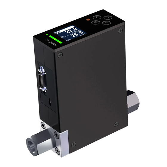
Digital Mass Flow Controller
Model F4Q
User's Manual for RS-485
Communication Functions
Thank you for purchasing your Azbil
Corporation product.
This manual contains information for
ensuring the safe and correct use of
the product.
Those designing or maintaining
equipment that uses this product
should first read and understand
this manual. This manual contains
information not only for installation,
but also for maintenance,
troubleshooting, etc. Be sure to keep it
nearby for handy reference.
Advertisement
Table of Contents

Related Manuals for Azbil F4Q


Summary of Contents for Azbil F4Q
- Page 1 No. CP-SP-1458E Digital Mass Flow Controller Model F4Q User’s Manual for RS-485 Communication Functions Thank you for purchasing your Azbil Corporation product. This manual contains information for ensuring the safe and correct use of the product. Those designing or maintaining...
- Page 2 Considerable effort has been made to ensure that this manual is complete and accurate, but if you should find an omission or error, please contact us. In no event is Azbil Corporation liable to anyone for any indirect, special, or consequential damages as a result of using this product.
- Page 3 Conventions Used in This Manual „ The safety precautions explained below aim to prevent injury to you and others, and to prevent property damage. Warnings are indicated when mishandling this product may WARNING result in death or serious injury. Cautions are indicated when mishandling this product may CAUTION result in minor injury or property damage only.
-
Page 4: Safety Precautions
Use this product within the operating conditions (for temperature, humidity, voltage, vibration, shock, mounting orientation, atmosphere, etc.) given in the specifications in Digital Mass Flow Controller Model F4Q User’s Manual (CP-UM-5978JECK). Otherwise there is a danger of device failure. Before wiring the device, turn the power off. Otherwise there is a danger of device failure. -
Page 5: The Role Of This Manual
The Role of This Manual There are four different manuals related to model F4Q. Read them as necessary for your specific requirements. If you do not have a manual you require, please contact us or one of our dealers. Digital Mass Flow Controller Model F4Q User’s Manual for RS-485 Communication Functions Document No. -
Page 6: Copyright, Licenses, And Registered Trademarks
Copyright, licenses, and registered trademarks · Modbus is a trademark and the property of Schneider Electric SE, its subsidiaries and affiliated companies. -
Page 7: Table Of Contents
Contents Conventions Used in This Manual Safety Precautions The Role of This Manual Copyright, licenses, and registered trademarks Chapter 1. Overview 1 - 1 Overview Features „ „ System configuration Chapter 2. Wiring 2 - 1 RS-485 Connection 2 - 2 Terminal Layout of This Device Chapter 3. - Page 8 Chapter 5. Modbus Communication (RTU Mode) 5 - 1 Communication Procedure 5 - 2 Message Structure „ Overview of Modbus-RTU Frame „ Silent interval „ Function code Check code „ Error termination code „ Conditions under which no response message is returned (no-response „...
-
Page 9: Chapter 1. Overview
Chapter 1. Overview 1 - 1 Overview Model F4Q (hereafter also “this device” or “the slave station”) can exchange data with host devices (master stations) such as a PC or a PLC via RS-485 communication. „ Features • The master station transmits read and write commands to slave stations. -
Page 11: Chapter 2. Wiring
Chapter 2. Wiring 2 - 1 RS-485 Connection A sample connection is shown below. Slave station (this device, etc.) Relay terminal block Terminating resistor Slave station (this device, etc.) Shielding Master station Slave station (this device, etc.) Shielding Relay terminal block Terminating resistor Slave station (this device, etc.) -
Page 12: Terminal Layout Of This Device
Digital input 2 (+) Digital input 3 (+) D.GND Digital signal (−) Common ground for digital signals Not connected Not connected Note • For wiring not related to the RS-485 communication line: Digital Mass Flow Controller Model F4Q User’s Manual, CP-SP-1461E. - Page 13 Chapter 2. Wiring Compatible connectors (all made by Japan Aviation Electronics Industry, Limited) z Solder type Compatible Plug Hood Clamp plate Appropriate wire outer diameter (reference) 22–30 AWG DF02P020F22A1 Hood Lock spring Straight DF02D020A11 DF02HCLP05A φ6.5–7.0 for EMI long DF02HCLP02A φ7.0–7.5 shielding DF02HCLP01A...
-
Page 15: Chapter 3. Settings
Chapter 3. Settings 3 - 1 Communication Function Settings Specify the following to use the communication function of this device. Display Parameter name Settings and description Initial value Notes Communication address setting 0: Communication function C-30 disabled 1 to 127 Transfer speed selection 0: 38400 bps C-31... -
Page 16: Setup Method
Note • Settings can also be specified using the MLP-F4Q Smart Loader Package for the F4Q digital mass flow controller. User’s Manual for Smart Loader Package Model MLP-F4Q for Digital Mass... -
Page 17: Chapter 4. Cpl Communication
Chapter 4. CPL Communication 4 - 1 Communication Procedure The following is the communication procedure in its simple form: (1) The master station sends an instruction message to slave stations specifying the station it wishes to communicate with. (2) The slave station receives the instruction message, and performs read or write processing according to the content of the message. -
Page 18: Message Structure
4 - 2 Message Structure „ Overview of a CPL Frame A message consists of the following two layers. Both the instruction message from the master station and the response message from the slave station take this form. • Data link layer: This layer contains the basic information required for communication. - Page 19 Chapter 4. CPL Communication „ Data link layer The data link layer contains eight items of basic information necessary for transmitting a message. The instruction message and response message have the same structure in the data link layer. The data link layer has a fixed length. The position of each item of data and its length are prescribed.
- Page 20 Chapter 4. CPL Communication • If “0” is set on a slave station, its RS-485 communication function will be disabled. To enable a station to communicate, be sure to set its address to “1” or above. • Do not send a command addressed to device address “0” from the master station.
- Page 21 Chapter 4. CPL Communication Handling Precautions • The checksum of the instruction message cannot be omitted. CR and LF (Carriage Return / Line Feed) Role : These indicate the end of a message. Description : "CR" is (0DH), and "LF" is (0AH). CR and LF must be used as a pair.
- Page 22 Chapter 4. CPL Communication „ Application layer The application layer contains instruction codes, start data address, data, number of data records, and information on the success of the instruction message (termination code). In the application layer, the structure of the instruction message is different from that of the response message.
-
Page 23: Description Of Commands
Chapter 4. CPL Communication 4 - 3 Description of Commands „ RS command (decimal format consecutive data read) RS command instruction message This is a command—in one message—to read the contents of consecutive data addresses from the specified read start data address. The application layer consists of the following three types of data. -
Page 24: Data Link Layer
Chapter 4. CPL Communication z Termination code Role : This tells how the instruction message was processed by the device. Different codes are used according to the result of processing. A response message always includes a termination code. 4 - 4 Termination Code (p. 4-16) (for termination code types) 1. -
Page 25: Application Layer
Chapter 4. CPL Communication Ex.: “0123” (30H, 31H, 32H, 33H) is not allowed. Ex.: “ 123” (20H, 31H, 32H, 33H) is not allowed. If the number is 0, one "0" is used. • Ex.: “0” (30H). Ex.: “00” (30H, 30H) is not allowed. Negative numbers are preceded by a minus sign (2DH). - Page 26 Chapter 4. CPL Communication 2. Read start data address Role : This specifies by a four-digit hexadecimal number the first data address to be read. Description : 6 - 2 Communication Data Table (p. 6-3) (for the relationship between data addresses and read data) Do not add “W”...
- Page 27 Chapter 4. CPL Communication 2. Error response If there is an error in the instruction message so that data cannot be read out normally, an error response is returned. The figure below shows an example of an error response. ("**" stands for the error code.) Termination code (** = an error code) 02H 30H 31H 30H 30H 58H *H...
-
Page 28: Ws Command (Decimal Format Consecutive Data Write)
Chapter 4. CPL Communication „ WS command (decimal format consecutive data write) WS command instruction message This is a command—in one message—to consecutively write the contents of multiple consecutive data addresses starting at the specified start data address. The application layer of the write instruction consists of the following three types of data. - Page 29 Chapter 4. CPL Communication Response message to the WS command If the data in the data link layer is correct, only a termination code is returned. 4 - 4 Termination Code (p. 4-16) (for termination code types) 1. Normal response If data is written correctly, a normal response is returned. ...
-
Page 30: Wd Command (Hexadecimal Format Consecutive Data Write)
Chapter 4. CPL Communication „ WD command (hexadecimal format consecutive data write) WD command instruction message This is a command—in one message—to consecutively write fixed-length data in hexadecimal format to multiple consecutive data addresses starting from the specified start data address. This command is suitable for handling data in ladder programs sent by PLC communications as the data is of a fixed length. - Page 31 Chapter 4. CPL Communication Description : The range of values that can be written varies depending on the data address. The address to which to write data is sequentially incremented by 1 following the starting data address. Up to 10 data records can be written in one message. Response message to the WD command If the data in the data link layer is correct, only a termination code is returned.
- Page 32 Chapter 4. CPL Communication 4 - 4 Termination Code The following table shows termination codes. Termination Type Description Note code Normal Normal termination Error There was an error in the The data cannot be converted to a number, “W” is not set, the data address or the number position of the comma is incorrect, etc.
-
Page 33: Timing Specifications
Chapter 4. CPL Communication 4 - 5 Timing Specifications „ Timing for response messages The response time of this device, from the time when the master station finishes sending the instruction message until the time when it begins to receive the response message from the slave station, is shown below. - Page 34 Chapter 4. CPL Communication 4 - 6 Character Code Table The CPL protocol of this product supports characters in the ASCII character code table. Upper Lower Space " & < ¥ ¦ − > ˜ The shaded parts of the table above ( ) are not used in this communication system.
-
Page 35: Modbus Communication (Rtu Mode)
Chapter 5. Modbus Communication (RTU Mode) 5 - 1 Communication Procedure The following is the RS-485 communication procedure in its simple form: (1) The master station sends an instruction message to slave stations specifying the station it wishes to communicate with. (2) The slave station receives the instruction message, and performs read or write processing according to the content of the message. -
Page 36: Message Structure
Chapter 5. Modbus Communication (RTU Mode) 5 - 2 Message Structure „ Overview of Modbus-RTU Frame All messages use binary data. • Modbus-RTU communication frame Frame structure Number of bytes Description (Start) Silent interval Address Device address Function For details, see on the particular function code Data For details, see on the particular function... -
Page 37: Check Code
Chapter 5. Modbus Communication (RTU Mode) „ Check code In RTU mode, CRC check codes are included in both command and response messages. Calculation of CRC check code The part of the message from the device address to immediately before the check code is used for the calculation. -
Page 38: Error Termination Code
Chapter 5. Modbus Communication (RTU Mode) Example of CRC calculation Device address is 1, function code is 03, start data address is 2001 (0x07D1), and the number of data records to read is 1. Address Function Data address (upper byte) Data address (lower byte) Number of data records to read (upper byte) -
Page 39: Conditions Under Which No Response Message Is Returned
Chapter 5. Modbus Communication (RTU Mode) Of the Modbus protocol exception codes, the following are supported. Exception code (error termination code) Error code Description Notes • ILLEGAL FUNCTION Unsupported function code No processing was performed. • ILLEGAL DATA VALUE Start data address error (inaccessible area) •... -
Page 40: Description Of Commands
Chapter 5. Modbus Communication (RTU Mode) 5 - 3 Description of Commands „ Function 03 (multiple data read command) Function 03 is the command for reading multiple data records. The command and normal response formats are shown in the table. Note •... - Page 41 Chapter 5. Modbus Communication (RTU Mode) Error response: Device address Function code Error termination code The function code when an error occurs (here, 83H) is obtained by flipping the most significant bit of the function code (0x03) to 1.
-
Page 42: Function 06 (One Data Write Command)
Chapter 5. Modbus Communication (RTU Mode) „ Function 06 (one data write command) Function 06 is the command for writing one data record. The command and the normal response have the same format. Note • Error termination code (p. 5-4) (for details of error response) „... -
Page 43: Function 16 (Multiple Data Write Command)
Chapter 5. Modbus Communication (RTU Mode) „ Function 16 (multiple data write command) Function 16 is the command for writing multiple data records. The command and normal response formats are shown in the table. Note • Error termination code (p. 5-4) (for details of error response) „... - Page 44 Chapter 5. Modbus Communication (RTU Mode) Normal response: Device address Function code Data address Number of data records Error response: Device address Function code Error termination code The function code when an error occurs (here, 90H) is obtained by flipping the most significant bit of the function code (0x10) to 1.
- Page 45 Chapter 5. Modbus Communication (RTU Mode) 5 - 4 Timing Specifications Timing specifications are the same as those of CPL communications. 5 - 4 Timing Specifications (p. 5-11) (for details) For Modbus communication, pay attention to the interval between frames (silent interval). 5-11...
-
Page 47: Communication Data
Chapter 6. Communication Data 6 - 1 Basic Information for Handling Communication Data „ Communication data types and formats Types of communication data Communication data can be categorized as follows: • Data related to the device • Data related to operating status •... - Page 48 F4Q, it is defined by the type of data. Handling Precautions • Be sure to do an operation check when replacing a model MQV with the F4Q. Digital Mass Flow Controller Model F4Q User's Manual, CP-SP-1461E (for details)
-
Page 49: Meaning Of The Symbols In Columns R And W
Chapter 6. Communication Data 6 - 2 Communication Data Table The following table shows the predefined address for each type of data and whether or not reading or writing is allowed. „ Meaning of the symbols in columns R and W ✓: Allowed ×... -
Page 50: Data Related To Operating Status
× A code indicating the device status is compatibility with the given for reference. Use only when replacing an older model MQV is replaced with the F4Q. Digital I/O status bit 1202 (04B2) ✓ × For an RS command, statuses are expressed as decimal numbers. - Page 51 Chapter 6. Communication Data Item Data range Data address Notes / [unit] Decimal (hexadecimal) ✓ Number of the SP 0–7 1205 (04B5) If “3” (SP No. switching) is set for C-10, currently in use C-11, or C-12 (Digital input 1–3 function assignment), the setting cannot be changed by communication.
- Page 52 Chapter 6. Communication Data *1. Alarm status bits for compatibility with the MQV (address 1201) Bit No. Item Description Flow rate deviation lower limit event 0: OFF. 1: ON (AL01) Flow rate deviation upper limit event 0: OFF. 1: ON (AL02) Undefined (normally 0) –...
-
Page 53: Data Related To The Instantaneous Flow Rate Setpoint
Programmable ROM error 0: OFF. 1: ON Run-time error 0: OFF. 1: ON Handling Precautions • Digital Mass Flow Controller Model F4Q User's Manual, CP-SP-1461E (for details of each status) „ Data related to the instantaneous flow rate setpoint Item Data range... -
Page 54: Data Related To Total Flow Volume
Chapter 6. Communication Data „ Data related to total flow volume Item Data range Data address Notes / [unit] Decimal (hexadecimal) Cumulative flow event 0 to 9999 or 0 to 1601 (0641) ✓ ✓ The method for combining setting (last digits) 0xFFFF upper and lower digits/bits and Note: Address... -
Page 55: Data Related To Function Settings
When writing total flow volume–related data, use the reverse procedure and write the separate values. „ Data related to function settings Note • Digital Mass Flow Controller Model F4Q User's Manual, CP-SP-1461E (for details of the functions) Item Data range Data address Notes... - Page 56 Chapter 6. Communication Data Item Data range Data address Notes / [unit] Decimal (hexadecimal) ✓ ✓ 0: Not used (OFF at all 2007 (07D7) (C-07) times) Digital output 1 type 1: ON when total flow assignment event occurs ✓ ✓...
- Page 57 Chapter 6. Communication Data Item Data range Data address Notes / [unit] Decimal (hexadecimal) ✓ ✓ (C-10) 0: Not used 2010 (07DA) 1: While the input is ON, the total value remains 0 and does not Digital input 1 function 1: Totalized flow reset increase.
- Page 58 Chapter 6. Communication Data Item Data range Data address Notes / [unit] Decimal (hexadecimal) ✓ ✓ (C-15) 0: Disabled 2015 (07DF) Flow rate deviation 1: Enabled only for event setup upper limit event 2: Enabled only for lower limit event 3: Enabled for upper/ lower limit event ✓...
- Page 59 Chapter 6. Communication Data Item Data range Data address Notes / [unit] Decimal (hexadecimal) (C-25) Always 0 2025 (07E9) – – Returns “0” when the setting is read and returns a normal response when Undefined written. ✓ ✓ (C-26) The same as C-18, Gas 2026 (07EA) type selection 1.
- Page 60 Chapter 6. Communication Data Item Data range Data address Notes / [unit] Decimal (hexadecimal) ✓ ✓ (C-35) 0: Disabled 2035 (07F3) SP limit function 1: Only upper limit enabled 2: Only lower limit enabled 3: Upper and lower limits enabled ✓...
- Page 61 Zero output: 0 V or 0 mA is output. Analog output when 1: Zero output Full output: approx. 6.2 V or approx. error occurs 24.8 mA is output. 2: Full output : It may be necessary to change the setting when replacing the MQV with the F4Q. 6-15...
-
Page 62: Data Related To Parameter Settings
Chapter 6. Communication Data „ Data related to parameter settings Item Data range Data address Notes / [unit] Decimal (hexadecimal) (P-1) (0.5 to 100 % FS)* 2201 (0899) ✓ ✓ The value is without a decimal point.* Flow rate OK judgment range ✓... - Page 63 Chapter 6. Communication Data Item Data range Data address Notes / [unit] Decimal (hexadecimal) ✓ ✓ (P-15) 0 to 9999 2215 (08A7) Specifies the change in flow rate per second. SP ramp control slope 1 Note: The unit for the setting varies ✓...
- Page 64 Chapter 6. Communication Data Item Data range Data address Notes / [unit] Decimal (hexadecimal) ✓ ✓ (P-29) 0 to 9999 [s] 2229 (08B5) When set to “0, ” the display is always lit. (display turnoff function is Automatic display off disabled) time ✓...
-
Page 65: Device Operation By Communication Commands
Chapter 7. Device Operation by Communication Commands By sending a write command to a specific data address, the following operations can be executed on this device. The data address and write data for each operation are as follows. Device operation Data address Write data Notes... - Page 66 Chapter 7. Device Operation by Communication Commands...
-
Page 67: Troubleshooting
• Check that the device address in the command frame transmitted from the host device matches the address set for the F4Q. “0” (no communication) is the the default address of the F4Q, but if the device address in the command frame is set to 00, the F4Q will not respond. -
Page 69: Specifications
Chapter 9. Specifications „ RS-485 specifications Item Specifications Transmission mode Balanced Transmission line 3-wire system Transmission speed 4800, 9600, 19200, 38400 (bps) Transmission distance 500 m max. Communication Half duplex system Synchronization Start-stop synchronization Data format 8-bit data, 1 stop bit, even parity Or 8-bit data, 2 stop bits, no parity Error detection Parity check, check code (checksum or CRC16) - Page 71 Revision History (CP-SP-1458E) Printed Edn. (New) Page No. Description June 2021...
- Page 74 Warranty period and warranty scope 1.1 Warranty period Azbil Corporation’s products shall be warranted for one (1) year from the date of your purchase of the said products or the delivery of the said products to a place designated by you.
- Page 75 Although acceleration of the above situation varies depending on the conditions or environment of use of the products, you are required not to use any Azbil Corporation’s products for a period exceeding ten (10) years unless otherwise stated in specifications or instruction manuals.
- Page 76 Specifications are subject to change without notice. (30) 1-12-2 Kawana, Fujisawa Kanagawa 251-8522 Japan URL: https://www.azbil.com 1st edition: June 2021 (V)
Need help?
Do you have a question about the F4Q and is the answer not in the manual?
Questions and answers