Advertisement
Quick Links
No. CP-SP-1373E
FRS100
Multiburner Controller
User's Manual
Thank you for purchasing the FRS100
Multiburner Controller.
This manual contains information for
ensuring the correct use of the FRS100.
It also provides necessary information
for installation, maintenance, and trou-
bleshooting.
This manual should be read by those
who design and maintain equipment
that uses the FRS100. Be sure to keep
this manual nearby for handy reference.
Advertisement

Subscribe to Our Youtube Channel
Related Manuals for Azbil FRS100


Summary of Contents for Azbil FRS100
- Page 1 FRS100. It also provides necessary information for installation, maintenance, and trou- bleshooting. This manual should be read by those who design and maintain equipment that uses the FRS100. Be sure to keep this manual nearby for handy reference.
- Page 2 If you should find an error or omis- sion, please contact Azbil Corporation. In no event is Azbil Corporation liable to anyone for any indirect, special or consequential damages as a result of using this product.
-
Page 3: Safety Precautions
SAFETY PRECAUTIONS I About Icons The safety precautions described in this manual are indicated by various icons. Please be sure you read and understand the icons and their meanings described below before reading the rest of the manual. Safety precautions are intended to ensure the safe and correct use of this prod- uct, to prevent injury to the operator and others, and to prevent damage to proper- ty. - Page 4 Before removing, mounting, or wiring the FRS100, be sure to turn off the power to the FRS100 and all connected devices. Failure to do so might cause electric shock. Do not connect a solenoid valve to the high potential side of the circuit.
- Page 5 WARNING If the pilot turndown test must be carried out repeatedly, completely shut down all equipment each time the test is finished, and completely discharge unburned gas or fuel that has accumulated in the ducts and combustion chamber. Failure to discharge unburned gas or fuel may result in an explosion.
- Page 6 CAUTION Follow all applicable regulations when doing the wiring work. Connect the blue signal lead from the AUD100 series Advanced Ultraviolet Flame Detector to terminal 5 and the white lead to terminal 6. Turning on the power when the flame detector is incorrectly wired could damage the AUD15C tube unit.
- Page 7 CAUTION If the safety shutoff has been activated, check all of the items on the checklists in Chapter 3, ADJUSTMENTS FOR TRIAL OPERATION before restarting the equipment. Check the flame current at least once per month. Doing so can prevent shutdowns caused by a weak flame current signal.
-
Page 8: Conventions Used In This Manual
Conventions Used in This Manual The following conventions are used in this manual: Handling Precautions Handling Precautions indicate items that the user should pay attention to when handling the FRS100. Note Notes indicate information that might benefit the user. (1), (2), (3): Numbers within parentheses indicate steps in a sequence or parts of an explanation. - Page 9 Contents SAFETY PRECAUTIONS Conventions Used in This Manual Chapter 1. OVERVIEW AND PRODUCT CONFIGURATION I Overview • • • • • • • • • • • • • • • • • • • • • • • • • • • • • • • • • • • • • • • • • • • • • • • • • • • • • • • • • • • • • • • • • I Features •...
- Page 11 AUD100 series advanced ultraviolet flame detector or flame rod for batch operation of a burner. For continuous burner operation (nonstop combus- tion for 24 h or longer), instead of the FRS100, use the AUR350C, which has a continuous self-checking function.
- Page 12 • The FRS100 operates each device according to a predetermined sequence and timing. 3. Safe startup • At every startup signal, the FRS100 checks for false flame in the flame detec- tor and flame detection circuit. • If a problem is detected, the FRS100 does not start the burner.
- Page 13 Chapter 1. OVERVIEW AND PRODUCT CONFIGURATION I Model selection guide Power Flame failure Model No. Rated power supply Model Flame detector consumption response FRS100B100 100 Vac 50/60Hz Standard C7007A, C7008A 3W max. 3 ±1 s Flame Rod model FRS100B200 200 Vac 50/60Hz (when flame voltage is 2 V) C7012A* , C7012C*...
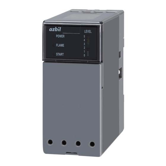
- Page 14 Chapter 1. OVERVIEW AND PRODUCT CONFIGURATION I Names of parts G FRS100 body LEVEL POWER FLAME START LEVEL : V oltage displayed 5 4.5 V or higher 4 3.5 to 4.5 V 3 2.5 to 3.5 V 2 1.5 to 2.5 V Cover DIN rail mounting plate G FRS50A100 subbase (sold separately) I Configuration G Flame Detector...
-
Page 15: Mounting And Wiring
Chapter 2. MOUNTING AND WIRING 2 - 1 Mounting and Wiring the Subbase CAUTION Do not install where exposed to any of the following: • Certain chemicals or corrosive gases (ammonia, sulfur, chlorine, ethylene compounds, acid, etc.) • Splashing water or excessive humidity •... - Page 16 Chapter 2. MOUNTING AND WIRING G Mounting direction • Mount in a vertical plane so that the arrow on the subbase is facing upwards. • Mount so that the indicators are at the top of the front panel. Indicator • Do not mount as shown below. G DIN rail mounting (1) Pull the DIN rail mounting plate downwards.
- Page 17 (6) Press the controller into the subbase with the display facing upwards. (7) Tighten the mounting screw on the center of the body to fix onto the subbase with a maximum torque of 0.3 N•m. Subbase FRS100 Push the FRS100 into the subbase Tighten the screw and fix Cover...
- Page 18 Chapter 2. MOUNTING AND WIRING 2 - 2 Wiring WARNING Wire terminals 1 and 2 so that they receive power continuously whenever the power switch is turned on. This is absolutely necessary to ensure operation of the self-check circuits at startup. Therefore, do not wire a thermostat between the power switch and terminal 1 or 2.
- Page 19 Chapter 2. MOUNTING AND WIRING I Manual ignition (intermittent pilot) High potential Low potential Blower on-off circuit / Prepurge circuit Limit/Interlock circuit (limit switch, interlock switch) Power Power circuit Ignition switch Start check circuit Ignition transformer Operation input circuit Pilot valve 1 Prepurge completion Burner start...
- Page 20 All loads are de-energized, and when the flame • (Start check operation detector detects the flame failure, relay 2K turns off. LED turns off) The FRS100 returns to standby status and waits for the next start signal. (3)Burner start contacts ON (6)Blower stop...
- Page 21 Power across terminals 7 and 2 is cut, and relay (Start check operation 1K turns off. LED turns off) The FRS100 returns to standby status and waits for the next start signal. (3)Burner start contacts ON (6)Blower stop Start check (2s)
- Page 22 Power across terminals 7 and 2 is cut, and relay (Start check operation 1K turns off. LED turns off) The FRS100 returns to standby status and waits for the next start signal. (3)Burner start contacts ON Start check (2s) (2)Blower operation...
- Page 23 4, and the load is not energized. Blower stop The power across terminals 7 and 2 is cut off, and the FRS100 returns to standby status and waits for the next start signal. If the false flame signal is continuous, the FLAME LED is also ON continuously.
- Page 24 Chapter 2. MOUNTING AND WIRING I Burner flame monitoring only (In a case where the FRS100 is not used in its usual combustion safety role of shutting valves, etc.) High potential Low potential Power Power circuit Burner Start check circuit...
- Page 25 OFF Since the flame detector detects a flame failure, • (FLAME LED turns off) relay 2K turns off. The FRS100 returns to standby • Flame output OFF status and waits for the next start signal. (1)Power ON (2)Start contacts ON...
- Page 26 8 is cut off, and the start check completion • Start check completion output turns off. output OFF The FRS100 returns to standby status and waits for the next start signal. (1)Power ON (2)Start contacts ON (4)Start contacts OFF Start check (2s) Start contact (term.7-2)
- Page 27 8 is cut off, and the start check completion output • Start check completion turns off. output OFF The FRS100 returns to standby status and waits for the next start signal. (1)Power ON (2)Start contacts ON (4)Flame failure Start check (2s)
- Page 28 1K does not turn on because a false flame is detected. Start contacts OFF Power across terminals 7 and 2 is cut off. The FRS100 returns to standby status and waits for the next start signal. If the false flame signal is continuous, the FLAME LED is also ON continuously.
- Page 29 Chapter 2. MOUNTING AND WIRING I Wiring the flame detector CAUTION If the FRS100C is used, connect the AUD110C detector’s signal leads from terminals F and G to terminals 5 (F) and 6 (G) of the FRS respectively. In the case of the AUD100C, connect the detector’s blue signal lead to terminal 5 (F) and the white lead to terminal 6 (G).
- Page 30 This device will not be able to prevent the valve from opening and fuel from flowing out. G Correct connection High potential (H) FRS100 100 V Power Low potential (G) (Ground fault)
- Page 31 Chapter 2. MOUNTING AND WIRING I Wiring the surge absorber Wire as shown below when using a surge absorber (model No.83968019-001, ordered separately) for protection from lightning surge. Handling Precautions • Use a JIS C 3306, 0.75 mm power lead (lead diameter 0.18, 30-strand) or higher for wiring to the power supply.
- Page 32 Chapter 3. ADJUSTMENTS FOR TRIAL OPERATION WARNING Do not allow the pilot or main burner "Safety Time" (ignition trial time) to exceed the specifications of the burner or equipment manufacturer. If they do, fuel may accumulate in the combustion chamber and form an explosive air- fuel mixture, resulting in a serious explosion hazard.
- Page 33 Chapter 3. ADJUSTMENTS FOR TRIAL OPERATION • Make sure that the flame detector is properly mounted. (Refer to its instruction manual.) • Disconnect the loads and flame detector wiring. Measure the insulation resis- tance across the terminals and panel ground, and make sure that the resistance is 50 MΩ...
- Page 34 Chapter 3. ADJUSTMENTS FOR TRIAL OPERATION I Pilot turndown test WARNING Do not allow the pilot or main burner "Safety Time" (ignition trial time) to exceed the specifications of the burner or equipment manufacturer. If they do, fuel may accumulate in the combustion chamber and form an explosive air-fuel mixture, resulting in a serious explosion hazard.
- Page 35 Chapter 3. ADJUSTMENTS FOR TRIAL OPERATION (5) Close the pilot manual valve slowly. The pilot flame will gradually grow small- er. Continue to close the manual valve until the flame detector can not detect the flame. Record the gas pressure immediately before the flame relay turns OFF and the combustion lamp is lit up.
- Page 36 Chapter 3. ADJUSTMENTS FOR TRIAL OPERATION I Ignition spark response test CAUTION Make sure that the flame detector does not detect the ignition spark. If the flame detector can detect the spark, change the detector's line of sight or change the ignition electrode's position. Make sure the flame detector does not detect ultraviolet rays other than those of the burner flame.
- Page 37 Chapter 3. ADJUSTMENTS FOR TRIAL OPERATION G Cautions regarding UV sources other than flames The table below shows various radiation sources other than the burner flame that may activate the flame detector. Make sure that the flame voltage is not affected under any conditions of the flame response test.
-
Page 38: Maintenance And Inspection
WARNING Before removing, mounting, or wiring the FRS100, be sure to turn off the power to the FRS100 and all connected devices. Failure to do so might cause electric shock. Even after the power to this device is turned off, terminal F continues to hold an electrical charge. - Page 39 Chapter 4. MAINTENANCE AND INSPECTION I Troubleshooting If a problem occurs, remove the front cover of the controller. Determine the operat- ing state of the controller and type of trouble by checking the start check, POWER and FLAME LED display states. The start check LED is located in the center inside the cover, and the POWER and FLAME LEDs are located on the front display.
- Page 40 • Procedure for the AUD100C + AUD15C (1) Remove the AUD15C from the socket. (2) Supply power to the FRS100. (3) Measure the DC voltage in the socket with a digital voltmeter or tester. • Connect the plus probe to the No. 1 pin on the socket (white lead wire) •...
- Page 41 Chapter 4. MAINTENANCE AND INSPECTION G Connecting a flame simulator Handling Precautions • Do the operation check in one sitting, and afterwards remove all test wiring at once. • Do not touch terminals (F) and (G) during the operation check. Doing so might cause electric shock.
-
Page 42: Chapter 5. Specifications
Chapter 5. SPECIFICATIONS I Specifications Item Specifications Rated power supply 100 Vac 50/60 Hz 200 Vac 50/60 Hz 220 Vac 50/60 Hz Allowable voltage -15 to +10 % of rated voltage Power consumption FRS100B -2: 3W max. FRS100C -2: 7W max. Contact ratings 250VA: terminal 3-4 for flame output 250 VA (1K and 2K) : terminal 3-8 for start check output 250 VA (1K) - Page 43 Chapter 5. SPECIFICATIONS I External dimensions G External dimensions when attached to the subbase (Unit: mm) DIN rail Subbase (FRS50A100, sold separately) FRS100 LEVEL POWER FLAME START Cover *1. Space required to mount and remove the body *2. Space required to mount and remove the body from DIN rail...
- Page 44 Chapter 5. SPECIFICATIONS G FRS50A100 subbase M3.5 terminal screws (8) DIN rail Subbase mounting holes (2) DIN rail mounting plate...
-
Page 45: Revision History
Revision History Printed Manual Number Edition Revised pages Description date CP-SP-1373E 1st Edition Jan. 2014... -
Page 46: Terms And Conditions
In the case of products that Azbil Corporation has repaired for a fee, the repaired part only shall be warranted for three (3) months from the time of delivery to the location designated by the customer. - Page 47 Azbil Corporation's products every 5 to 10 years unless otherwise specified in specifications or instruction manuals.
- Page 48 Specifications are subject to change without notice. (09) 1-12-2 Kawana, Fujisawa Kanagawa 251-8522 Japan URL: http://www.azbil.com 1st edition: Jan. 2014 (K)
Need help?
Do you have a question about the FRS100 and is the answer not in the manual?
Questions and answers