
Related Manuals for Groeneveld Twin-3


Summary of Contents for Groeneveld Twin-3
- Page 1 General Manual T w i n Automatic Greasing System Twin-3 EG1703P03 Your efficiency is our Challenge! ASC Form # 80-1052 Rev 9/2013...
- Page 2 Groeneveld. This applies also to the drawings and diagrams appended. Groeneveld reserves the right to change parts at any time, without prior or direct notice to the customer. The contents of this manual may also be changed without prior notice.
-
Page 3: Table Of Contents
Twin-3 display - - - - - - - - - - - - - - - - - - - - - - - - - - - - - - - - - - - - - -... - Page 4 Automatic Greasing System Twin-3 Table of Contents EG1703P03...
-
Page 5: Preface
Automatic Greasing System Twin-3 Preface This general manual gives a description of the Twin automatic greasing system. It aims at giving insight in the system’s operation and possibilities. Furthermore, in this manual you will find the technical data on several components of the Twin automatic greasing system. -
Page 6: General Information
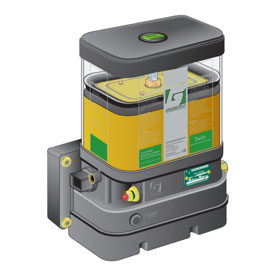
General information Introduction With an automatic greasing system of Groeneveld all grease points of a vehicle or machine are lubricated automatically at the correct moment and with the correct amount of grease. Because greasing takes places while the vehicle or machine is in operation, the applied grease is spread optimally over the whole surface to be greased. - Page 7 Automatic Greasing System Twin-3 Groeneveld Twin automatic greasing system comprises the following parts (see Figure 1.1): An electric grease pump (plunger pump) with integrated grease reservoir and a digital control unit with data storage facility Primary grease line A Primary grease line B...
-
Page 8: Principle Of Operation
In this chapter the principles of operation of the various parts of the Twin automatic greasing system are discussed. The greasing cycle, pump unit, control unit, metering units, pressure switch, signal lamp and Twin-3 display are discussed. Greasing cycle Every greasing cycle consists of four phases. The greasing cycles are performed alternately by the grease lines-A and -B (see Figure 2.1). -
Page 9: Greasing Cycle B
Automatic Greasing System Twin-3 Pressure retaining phase The pressure retaining phase follows the pumping phase; a period in which the pressure in the primary grease line-A is maintained at a certain pressure. During the pressure retaining phase, the metering units can deliver the grease dosage, which (for various reasons) was not yet delivered during the pumping phase. -
Page 10: Twin Pump Unit
Automatic Greasing System Twin-3 Twin pump unit The Twin pump unit consists of various parts. These parts are shown in Figure 2.2. 1. Follower plate 10. Electro-motor 18. Guide rod follower plate 2. Grease reservoir 11. Control unit 19. Bleeding and grease overflow 3. -
Page 11: Control Unit
Automatic Greasing System Twin-3 2.3.1 Control unit The electronic control unit steers and controls the course of the greasing cycles. All system- and program-parameters are stored in it. The control unit processes malfunction reports, gives possible alarm reports and automatically records a log. All relevant incidents will be stored in the log. - Page 12 ON • ground to pin-3 is switched OFF Please refer to the Twin-3 Uni- or PC-GINA manual for the necessary parameter settings in order to activate one of the above mentioned possibilities. 12V 20A PUMP...
- Page 13 Automatic Greasing System Twin-3 12V 20A PUMP 24V 10A 12V 3A 24V 3A 2 GND 1 +15 POWER PUMP VAL1 VAL2 TEST 120 Ohm 5% 1W 1. Electric motor of pump 7. Battery 2. 5/2-way valve 8. Ignition switch 3. Minimum level switch 9.
-
Page 14: 5/2 Way Valve
Automatic Greasing System Twin-3 2.3.2 5/2 way valve When the 5/2-way valve is at stationary (not switched on by the control unit, see Figure 2.6), greasing will take place through primary grease line-A and the pressure in primary grease line-B... -
Page 15: Grease Reservoir And Its Follower Plate
At the beginning of every following greasing cycle a signal lamp in the cabin will flash or the yellow and green LED along with indication LO at the Twin-3 display is lit continuously as a warning that the reservoir has to be refilled. -
Page 16: Distribution Block And Metering Units
Automatic Greasing System Twin-3 Distribution block and metering units Various types of metering units with the Twin greasing system are available, each with a different grease output. Each grease point can receive the correct dose of grease per greasing cycle by a careful choice of the type of metering unit. -
Page 17: Principle Of Operation
Automatic Greasing System Twin-3 2.4.1 Principle of operation Two grease chambers are located in a metering unit (one for each primary grease line, A and B). These chambers are filled with an exact amount of grease. When the actual greasing takes places through one of both chambers, the grease is pressed from the chambers to the relevant grease point. - Page 18 Automatic Greasing System Twin-3 Phase 3 During pumping phase B grease is pressed into channel B (6). While the grease pressure is built up, piston (3) is pushed back leftwards, passed channel (8). The grease fills chamber (7) and pushes piston (4) back to the left.
-
Page 19: Pressure Switch
Automatic Greasing System Twin-3 Pressure switch The pressure switch notifies the control unit that sufficient pressure has been built up during the pumping phase and stops the pump. When the required pressure is not reached, the pumping phase is only ended after reaching the set maximum pumping time. An alarm will follow (signal lamp). - Page 20 Automatic Greasing System Twin-3 Figure 2.13 Second phase During the pressure decrease phase, as soon as the grease pressure in channel A is lower than the pressure force of the spring, the connection of the electrical contacts is broken. Phase 3 During pumping phase B grease is pressed into channel B.
-
Page 21: Signal Lamp
Automatic Greasing System Twin-3 Signal lamp The signal lamp is mounted in the field of vision of the driver and out of direct sunlight, because of the visibility of the signals. Possible this lamp can be combined with the operating push-button. The lamp shows the status of the greasing system and malfunction reports by means of flashing codes. -
Page 22: Twin-3 Display
With the switch-button (1) the desired operating/test mode can be selected and also errors can be reset (see Figure 2.17). The Twin-3 display is equipped with a 3-digit display (2). Herewith errors, the active duty mode and test mode (if applicable) can be displayed. The decimal dot (3) indicates whether the interval timer remains or is on standby (see paragraph 2.8.1). -
Page 23: Decimal Dot Of The 3-Digit Display
System error. Duty cycle selection possible only after the error has been solved. (See “Malfunction reports of Twin-3 display” on page 34). *) Indication shown when a Twin-3 display has been connected to a Twin-2 pump. NOTE The display is equipped with a light-sensitive cell. Therefore the light intensity of the LED’s is automatically dimmed when the surroundings become darker. -
Page 24: System Test
The signal lamp or the green LED at the display flashes during the cycle test(s). In case of a single cycle it will flash slowly (2-sec. on / 2-sec. off) and code “T1” will show at Twin-3 display. In a multiple cycle test it will flash rapidly (0,2-sec. -
Page 25: Single Greasing Cycle Test
Push the test push-button at pump for 2-6 seconds. The system will operate a single greasing cycle. During the operation the green LED at Twin-3 display or signal lamp at the duty mode push-button will flash slowly (2-sec. on / 2-sec. off). -
Page 26: Multiple Greasing Cycle Test
Push the test-button at pump for more then 6 seconds. The system will operate a multiple greasing cycle. During the operation the green LED at Twin-3 display will flash quickly (0,2-sec. on / 0,2- sec. off). A code “T2” and a running-decimal-dot will be indicating its pump, pressure retaining and pressure decrease phase at Twin-3 display;... -
Page 27: Fast Automatic Cycle Session
When during the session a number of cycles fail in succession, the session ends and pump disables. The Twin-3 display will show the red LED and the cause by error code (see “Malfunction reports of Twin-3 display” on page 34). All data during such a session will be stored as fast automatic cycles and successful finished cycles. -
Page 28: Maintenance
Periodic checks Check the grease level in the reservoir and its condition. Do not fill the reservoir until the low level warning comes on at the Twin-3 display or on the signal lamp of the duty mode push- button switch;... -
Page 29: Bleeding The System
Automatic Greasing System Twin-3 NOTE When after a few minutes still no grease exits the pump outlet we advise to pump some oil into the reservoir along the filler-coupling (500 cc or 1/8 gallon will be sufficient). This will help to push aside the air-pockets around the pump piston. -
Page 30: Refilling The Grease Reservoir
The yellow LED and LO code at Twin-3 display or signal lamp of duty mode push-button will go OFF automatically when pump reservoir has been refilled. NOTE Do not fill the reservoir until the low level warning comes on at the Twin-3 display or on the signal lamp of the duty mode push-button switch. NOTE It is possible that during or directly after the refilling, some grease comes from the bleeding opening of the pump (left side). -
Page 31: Finding Malfunctions
The signal lamp or all 3 LED’s including 3-digit display no longer lights up when ignition is switched ON. • The signal lamp or Twin-3 display shows a malfunction. • Retrieving a fault code on the signal lamp by means of the duty mode push-button or fault codes are shown at Twin-3 display (see paragraph 4.6.3). -
Page 32: Malfunction Finding Table
Automatic Greasing System Twin-3 4.6.3 Malfunction finding table To make it easier to find malfunctions (when no Uni- or PC-GINA is available), refer to the malfunction finding table. In this table, probable causes of malfunctions and their solutions are listed. Because malfunction reports through the Twin display varies a little from the reports through the signal lamp, a separate table is inserted. - Page 33 Automatic Greasing System Twin-3 Malfunction Cause Solution 4. Signal lamp lights The state of the pressure switch continuously for 2 minutes at did not change from open to the end of pumping phase. closed. Possible causes: a. The primary grease line leaks.
- Page 34 Automatic Greasing System Twin-3 Malfunction reports of Twin-3 display Error code / malfunction Cause Solution a. No supply voltage at the display. a. Check fuses and/or wire connec- tion (yellow wire). Repair when One or all LED’s necessary. b. Ground wire disconnected.
- Page 35 Automatic Greasing System Twin-3 Error code / malfunction Cause Solution The pressure switch did not close during a greasing cycle in primary line-B. Successive no pressure Possibly caused by: in line-B a. Broken/damaged primary line-B. a. Check condition of primary lines and its connectors.
- Page 36 Automatic Greasing System Twin-3 Error code / malfunction Cause Solution Cycles that have not been per- formed, due to grease reservoir ran empty and disabled the pump, Empty reservoir caused by: a. Max. number of cycles with an a. Refill the reservoir. Proceed with activated low level switch paragraph 4.5.2 “Filling the res-...
- Page 37 Automatic Greasing System Twin-3 Error code / malfunction Cause Solution Control unit detected a too high cur- rent draw to pump motor and aborted the attempted cycle, caused Successive pump over current a. Short circuit in wiring of motor a. Check the wiring of motor.
- Page 38 Automatic Greasing System Twin-3 Error code / malfunction Cause Solution Control unit detected a too low cur- rent draw to first coil of the 5/2-way valve in combination with Successive valve-2 initial “system on pressure before open loads cycle” error, caused by: a.
- Page 39 1063 or lower). Such a control error information is required. unit does not supply additional info on the cause of the error like the Twin-3 pump does since SW version 1078 b. An error cause that is not b. Replace control unit.
-
Page 40: Retrieving A Fault Code Message By Signal Lamp
Automatic Greasing System Twin-3 4.6.4 Retrieving a fault code message by signal lamp The fault message that caused the system to malfunction can be retrieved by pushing the duty mode push-button for at least 6 seconds (20-sec. max). Directly after releasing the push button the signal lamp will show the fault message by flash code (does not function with switch-button on display). -
Page 41: Malfunction Finding Procedures
Automatic Greasing System Twin-3 4.6.5 Malfunction finding procedures A number of procedures to determine the correct cause of a certain malfunction are described below. Procedure to check pressure switch (valve) and its cable Disconnect the 2-pole connector from the pressure switch. - Page 42 Automatic Greasing System Twin-3 Procedure to check pump and 5/2-way valve Disconnect both primary grease lines from the pump outlet A and B. WARNING Check whether the system is pressureless before the system is opened! Connect a pressure gauge to each channel of the pump. Use pressure gauges that are suitable for a grease pressure of 250 bar.
- Page 43 Automatic Greasing System Twin-3 Procedure when an internal system leak is suspected Disconnect the primary grease line of outlet B of the pump. WARNING Check whether the system is pressureless before the system is opened! Switch ignition ON. Push the test push-button at the pump for about 4 seconds to start a cycle test.
-
Page 44: Technical Data
Automatic Greasing System Twin-3 Technical data Twin pump unit Maximum operating pressure: 250 bar Operating temperature: -20...+70°C Supply voltage: 12 or 24 Vdc Rating pump motor with valve (nominal at 20°C): Control unit absorption: 40mA (12/24 Vdc) Advised fusing: 10A (24 Vdc) -
Page 45: Signal Lamp
Automatic Greasing System Twin-3 Reservoir L1 [mm] L2 [mm] 6 Litres 8 Litres Figure 5.2 Dimensions Twin pump with a 6 or 8 litre reservoir Signal lamp Max. allowed power consumption: EG1703P03 Technical data 45... -
Page 46: Twin Display
Automatic Greasing System Twin-3 Twin display Regulations / EMC Off road ISO 13766-2006 Road transport 2004/104/EC Industrial equipment 2004/108/EC Environment Ambient operating temperature range: -25…+70 °C Storage temperature range: -25…+70 °C Casing humidity/dust: IP54 Electrical Supply operating voltage range: 9…32 VDC Max. - Page 48 Groeneveld Transport Efficiency B.V., Stephensonweg 12, 4207 HB Gorinchem, P.O. Box 777, 4200 AT Gorinchem, The Netherlands, Ph : +31 183 641 400, F : +31 183 624 474, http://www.groeneveld-group.com...
Need help?
Do you have a question about the Twin-3 and is the answer not in the manual?
Questions and answers