
Subscribe to Our Youtube Channel
Related Manuals for Groeneveld BreakAlube-3


Summary of Contents for Groeneveld BreakAlube-3
- Page 1 General Manual Automatic Greasing System BreakAlube-3 F600677R00 YOUR EFFICIENCY IS OUR CHALLENGE...
- Page 2 Groeneveld. This applies also to the drawings and diagrams appended. Groeneveld reserves the right to change parts at any time, without prior or direct notice to the customer. The contents of this manual may also be changed without prior notice.
-
Page 3: Table Of Contents
2.2 The BreakAlube-3 automatic greasing system ............ 6 COMPONENT DESCRIPTION ..........8 3.1 Properties .......................... 8 3.2 Composition of the BreakAlube-3 pump unit ............8 3.3 The control unit ......................10 3.3.1 Behaviour during power off / on ..............10 3.4 The plunger pump ....................... 10 3.5 Safety and control features .................. -
Page 4: Preface
This general manual gives a description of the BreakAlube-3 Automatic Greasing System. It aims at giving insight in the system’s operation and possibilities. Furthermore, in this manual you will find the technical data of several components of the BreakAlube-3 Automatic Greasing System. -
Page 5: General Information
The operator needs only to ensure the periodic topping up of the grease reservoir. Groeneveld’s automatic greasing system has been thoroughly tested to guarantee a long and trouble-free service life, even under severe operating conditions. Besides correct installation and the use of the prescribed type of grease, a periodic check of the operation is a condition for the continued good functioning of the system. -
Page 6: The Breakalube-3 Automatic Greasing System
Automatic Greasing System The BreakAlube-3 automatic greasing system The BreakAlube-3 pump is designed for use on excavators equipped with a hydraulic ham- mer. The pump is installed on the excavator and the grease is delivered to the hydraulic ham- mer by means of a hydraulic high pressure hose. The pump is activated by switching on the hydraulic hammer and pumps a quantity of grease to the hydraulic hammer, either at brief intervals or continuously, depending on the settings. - Page 7 General Manual General information F600775R00...
-
Page 8: Component Description
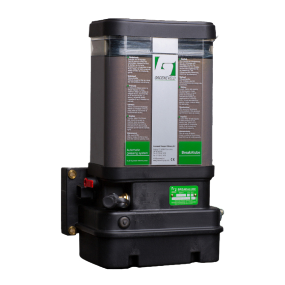
Automatic Greasing System 3. COMPONENT DESCRIPTION Properties The Groeneveld BreakAlube-3 pump unit has been specially developed for use on an excava- tor equipped with a hydraulic hammer. Characteristics: • Variable grease delivery between 0.2cc and 4cc per minute with an activated hydraulic hammer;... - Page 9 General Manual Component description F600775R00...
-
Page 10: The Control Unit
The control unit monitors the performance of various components of the greasing system and processes, stores and reports the malfunctions it detects. The control unit can be programmed or read out using a UniGINA (Universal Groeneveld tester INstallation and Analysis). -
Page 11: Safety And Control Features
General Manual Safety and control features 3.5.1 Maximum pressure indicator A relief valve (fitted with an electrical contact) is installed in the grease channel between the plunger pump and the pump outlet. This relief valve leads the grease back to the reservoir if the maximum grease pressure (300 bar) is exceeded during the pump phase of a grease cycle. -
Page 12: The Test Push-Button
BreakAlube-3 Automatic Greasing System The test push-button The test push-button on the pump unit has 3 functions: • Performing a test cycle. • Resetting the signal lamp and pump after solving the error(s). • Retrieving error codes stored in the memory bank of the control unit. -
Page 13: Resetting The Signal Lamp And Pump
General Manual 3.6.2 Resetting the signal lamp and pump Whenever the control unit has disabled the pump due error(s) (default setting: 10 errors in succession), the signal lamp will be lit continuously. The pump can be enabled using the test push-button, as follows: 1. -
Page 14: Signal Lamp
BreakAlube-3 Automatic Greasing System Signal lamp The signal lamp should be mounted in the field of vision of the driver and out of direct sunlight, because of the visibili- ty of the signals. The lamp shows the status of the greasing system and mal- functions reports by means of flashing codes. -
Page 15: Error Codes By Signal Lamp
General Manual 3.7.2 Error codes by signal lamp The pending errors stored in the memory bank of the control unit can be retrieved by using the test push-button on the pump unit. The signal lamp displays the pending errors by flashing: •... -
Page 16: Installation
Automatic Greasing System 4. INSTALLATION Overview To install the Groeneveld greasing system the following tasks must be performed: 1. Mounting the pump with integrated control unit. 2. Mounting the grease hoses and quick coupler. 3. Mounting the electrical wiring and signal lamp. -
Page 17: General Installation Directives
General Manual General installation directives 1. Check the contents of the parts kit using the parts list included in the kit. 2. Before start installing the greasing system, check whether the grease point of the hydraulic hammer is open and furnished with a sufficient amount of grease. If that is not the case, grease the grease point by hand. -
Page 18: Couplings And Grease Hoses
BreakAlube-3 Automatic Greasing System Couplings and grease hoses 4.5.1 Installation of the couplings 1. Determine the position for the quick coupler on the dipper arm of the machine before disconnecting the hydraulic hammer and mount or weld on a support bracket in this position. -
Page 19: Installation Of The Grease Hoses
General Manual 5. If the greasing point is in a unprotected position low down on the side of the hydraulic hammer, it should be moved to a higher and more protected position on the hammer using a thick-walled tube and/or welding block so that a safe transition can be made to a hose to the dipper arm of the machine. -
Page 20: Electrical Wiring
BreakAlube-3 Automatic Greasing System Electrical wiring Detailed wiring diagrams are available as aids to install the electrical wiring. Where possible, pre-assembled wiring harnesses are delivered. ATTENTION In order to avoid damage to the electrical signal of the machine, the supply line such as the +15 (red wire, pin 1) and the hydraulic hammer control signal line (green wire, pin 3) must be protected with the correct fuses. -
Page 21: Wiring Diagram
General Manual 4.6.3 Wiring diagram 1. Pump unit. 2. Control unit. 3. Pump motor. 4. Revolution sensor. 5. Relief valve switch (NC). 6. Minimum level switch (NC). 7. Test switch (NO). 8. Minimum pressure switch (NO). 9. Battery of the machine. 10. -
Page 22: Bleeding The System
BreakAlube-3 Automatic Greasing System Bleeding the system Because each hydraulic hammer supplier prescribes his own specific grease, we have decided to supply the pump with an empty grease reservoir (also pumps pre-filled with HammerLube grease NLGI 1.5 are available). For bleeding and testing the pump during production, how- ever, the pump with an empty grease reservoir has been filled with a minimum amount of HammerLube grease NLGI 1.5. -
Page 23: Putting The System Into Operation
General Manual Putting the system into operation Before putting the system into operation, ensure that the quick coupler in the grease hose to the hydraulic hammer is connected and that the UniGINA is connected to the pump. The switch on the ignition (+15) and check that the signal lamp comes on in between five seconds. - Page 24 BreakAlube-3 Automatic Greasing System • Also check the grease pressure of the system. For this, a pressure gauge must be connected to the pump as a standard, The pressure in the system must remain above the minimum set grease pressure of 20 bar and below the maximum grease pressure of 275/300 bar during every cycle to avoid an error being stored.
-
Page 25: Maintenance
General Manual 5. MAINTENANCE General The maintenance of the Groeneveld BreakAlube system can be combined with the normal maintenance of the machine. WARNING If a high-pressure steam/water jet is used to clean the machine, the pump unit should not be directly exposed to the jet. This to prevent water from entering the pump unit through its de-aerating opening. -
Page 26: Filling The Grease Reservoir
To be able to fill the reservoir using a special filling pump, a special filler coupling can be installed. Groeneveld can supply you with both mobile or stationary filling pumps (hand- or air-operated). 5.3.1 Filling procedure The grease filling pump must be suitable for NLGI-2 grease. -
Page 27: Trouble Shooting
General Manual Trouble shooting The greasing system is equipped with an electronic control unit with a memory bank. All rele- vant data concerning the functioning of the greasing system are stored in that memory bank. This data can be read out with the use of a UniGINA. 5.4.1 Recognizing malfunctions Malfunctioning are recognizable or discovered as follows: •... - Page 28 BreakAlube-3 Automatic Greasing System Problem Cause Solution The greasing point of the hy- Defective pump unit or block- Retrieve the error code. draulic hammer is too dry and a age in the system. If the outlet blocked (relief valve malfunction is indicated.
-
Page 29: Error Codes By Signal Lamp
General Manual 5.4.3 Error codes by signal lamp Error code / failure Cause Solution 10 : Currently no pending errors - 12: Outlet 1 blocked Maximum pressure exceeded during a pump cycle (relief valve opened), possible caused 1. Blocked grease hose. 1. - Page 30 BreakAlube-3 Automatic Greasing System Error code / failure Cause Solution 22: Open Load pump motor Control unit detected an in- terrupted power circuit to the pump motor and aborted the attempted pump cycle, possibly caused by: 1. Interrupted wiring. 1. Check wiring harness be- tween motor and circuit board and restore when necessary.
- Page 31 General Manual Error code / failure Cause Solution 24: Open Load hammer output Control unit detected an in- terrupted power circuit of the hammer output option, caused 1. This option is not in use and 1. Deactivate this option using a this option has been incorrect- UniGINA.
- Page 32 BreakAlube-3 Automatic Greasing System Error code / failure Cause Solution 41: Voltage drop Control unit encountered a suc- cessive power dip during pump start and aborted the attempt- ed cycle, caused by: 1. Faulty battery (machine). 1. Charge or replace battery.
-
Page 33: Technical Data Pump Unit
General Manual Technical data pump unit Maximum operating pressure: 300 bar Operating temperature: -20 ... +85 °C Power supply voltage: 12 or 24 Vdc Rating pump motor (nominal at 20°C): 36 W Rest current: 10 mA Advised fusing: 15A (12 Vdc) / 10A (24Vdc) Capacity grease reservoir: 4 litres Minimum level switch:... - Page 34 BreakAlube-3 Automatic Greasing System Notes F600775R00 Maintenance...
- Page 36 Groeneveld Transport Efficiency B.V. • Stephensonweg 12 • 4207 HB Gorinchem • P.O. Box 777 • 4200 AT Gorinchem The Netherlands • T. +31 (0)183 641 400 • F. +31 (0)183 624 474 • www.groeneveld-group.com...
Need help?
Do you have a question about the BreakAlube-3 and is the answer not in the manual?
Questions and answers