Table of Contents
Advertisement
Quick Links
Groeneveld-BEKA (North America)
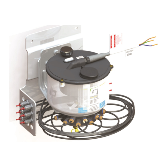
MultiLine SFi (MSFI) Manual
Applicable Pumps: AC15XXL-2-A, AC25XXL-2-A, AX13XXL-A, AX23XXL-A
Applicable Kits: MSFI-XXXX-XXXX
Maximum Working Pressure: 1740 psi (120 bar, 12 MPa)
Maximum operating temperature: 140°F/60°C
*(Note that operating close to maximum temperature will effect life of the pump)*
Minimum operating temperature: -31°F/-35°C (with grade 000 grease), 10°F/-12°C (with grade 2 grease).
IP Rating: IP66
Voltage: 24 VDC, 110/220 VAC (50/60Hz)
Power Rating: 4VA
Fuse Rating: 1A
*Max Pumpability Distance: 35ft (10.7m)
*Temperature & lubricant dependent
This print and the ideas and principles represented on the print are the property of Groeneveld-BEKA USA. This print is not to be copied or reproduced (even extracts) without prior
written consent of Groeneveld-BEKA. This manual is not intended to be a substitute for the specific recommendations of your equipment supplier. Every reasonable effort has been
made to ensure the accuracy of the information contained in this catalog, but no liability is accepted for errors, omissions or for any other reason.
MSFI - F801306
Advertisement
Table of Contents

Related Manuals for Groeneveld MultiLine SFi


Summary of Contents for Groeneveld MultiLine SFi
- Page 1 *Temperature & lubricant dependent This print and the ideas and principles represented on the print are the property of Groeneveld-BEKA USA. This print is not to be copied or reproduced (even extracts) without prior written consent of Groeneveld-BEKA. This manual is not intended to be a substitute for the specific recommendations of your equipment supplier. Every reasonable effort has been made to ensure the accuracy of the information contained in this catalog, but no liability is accepted for errors, omissions or for any other reason.
-
Page 2: Installation Warning
Installation Warning WARNING INSTALLATION Only install the Groeneveld-Beka AXL System if you are suitably qualified. Read installation instructions before commencing installation. If in doubt contact Groeneveld-BEKA at 937-276-4507. PERSONAL PROTECTIVE CLOTHING You must wear appropriate protective equipment when operating and servicing the equipment, this is to protect you from serious injury. -
Page 3: Ec Declaration Of Conformity
In accordance with ISO/IEC 17050-1:2010 Groeneveld-Beka UK Ltd 85a St Modwen Rd, Parkway Industrial Estate, Plymouth, Devon, United Kingdom, PL6 8LH. I hereby declare that: MultiLine SFi Automatic Lubrication Systems Equipment: In accordance with the following Directive (s): 2004/108/EC The Electromagnetic Compatibility Directive... - Page 4 Mounting and Clearance Select a suitable mounting point for the pump on the machinery, preferably in a position where it is protected from debris. Ensure adequate clear- ance for the looming and re-filling is provided (see image below for clearance allowances). Do not mount the pump onto ancillary equipment. Using the pump-mounted adhesive template (part number 31867-900), supplied, position and drill the bracket holes (mounting positions and bracket clearances detailed as per the above image).
- Page 5 Overview: The MultiLine SFi kits are pre-loomed from the pumping element to the bulkhead connections on the pump bracket. The push-fit connectors provide an easy installation of the lines to the bulkhead connectors. The lubrication line should be Groeneveld-BEKA ø4mm, semi-rigid, nylon tubing.
-
Page 6: Installation
Installation Typical System Installation Methods To connect the lubricant distribution lines to the bearing, as detailed on the previous page, remove the existing zerk fitting(s) (see images 1 and 2, below) and replace with the preferred push-fit or compression fitting(s) (see images 3 and 4, below). - Page 7 MSFi 12/24VDC Pump: Wiring and Programming Installation of the AC range of pumps should ideally incorporate direct connections to the vehicle ignition system. This provides automatic lubrication whenever the ignition is switched on. A memory, built into the pump’s printed circuit board, removes the possibility of over-lubrication on a short trip/multi-drop operation as the pump will continue operation of the programming from when the ignition was last switched off (i.e.
- Page 8 MSFi 12/24 VDC Pump: Overview and Operation The lubrication process starts after either the ignition is switched on (if set to continuous run mode and the pump is only powered when the ignition is on) or after the allotted dwell time (of the already programmed pump) has elapsed. The pump will run for 3 minutes and dwell for the allotted remaining time as programmed (6 minutes dwell, if 9-minute program, 9 minutes dwell if 12-minute program and 12 minutes dwell if 15-minute program).
-
Page 9: Wiring Information
MSFi 110/220 VAC Pump: Wiring and Timer Adjustment Wiring Information To access the internal PCB and adjust the run settings via the dip switch: Disconnect power to the pump. Remove lid screws x3 (see ‘A’), (Torqued to 0.6Nm). Remove lid (see ‘B’), making sure to retain the O-ring. Remove motor housing screws x4 ( see ‘C’), (Torqued to 1.2Nm). - Page 10 MSFi 110/220 VAC Pump: Overview and Operation The SFi range has been designed to provide reliable and virtually maintenance free service in the most demanding applications. The system is an electrically operated (110/220V) pump with integral controller and one or more lubricant distribution lines which connect each bearing directly to the respective pumping element via a bulkhead fitting situated on the sides of the mounting bracket.
- Page 11 Bulk fill adaptors (Part# MSF-A-QF) are also available on special request, which can be fitted instead of the grease nipple as shown on the examples below. DO NOT FILL FROM TOP FILL WITH NLGI 0, 1, 2 GRADE GREASE UNLESS INSTRUCTED BY GROENEVELD-BEKA. IMPORTANT NOTES: •...
-
Page 12: Recommended Lubricants
Recommended Lubricants Recommended Lubricants The AX Pump has been developed specifically to run with NLGI Grade 000, 1, 2 grease and FG3,0 fluid grease. Oils to a minimum viscosity of SAE80 are also acceptable. Do not use heavy, tackified greases, greases containing bentone/bentonite or greases containing molyb- denum and/or graphite. - Page 13 Order Method AC Pump Nomenclature Pump Reservoir Timer (Delay) Voltage Lube Points Config. Top Fill 1.25L Blink Code 12VDC 12-Port 2.0L 24VDC 24-Port Programmable 36-Port 0, 6, 9, 12, 27, 42, 57mins • All variants come with externally programmable blink code timer (continuous, 6, 9, 12, 27, 42, and 57min delay options) •...
- Page 14 AC and AX Pump Spares Item No. Part No. Description Qty. MSF-L-12DC SPARE LID ASSEMBLY - 12 VDC MSF-L-24DC SPARE LID ASSEMBLY - 24 VDC MSF-L-110V SPARE LID ASSEMBLY - 110 VAC MSF-L-220V SPARE LID ASSEMBLY - 220 VAC Includes motor, circuit boards, drive adapters and wire harnesses. AC-SP34 CIRCUIT BOARD - 12/24 VDC AX-SP2...
-
Page 15: Exploded View
Exploded View Note: Wiring/connection may differ from that shown. MSFI - F801306... -
Page 16: Accessories And Components
For up to 36 point system 20035 1” Spiral Wrap (13-35 tubes) 39694A250 1/4” Split Convolute (Single tube) 39694A375 3/8” Spit Convolute (2-4 tubes) 39694A500 1/2” Split Convolute (5-7 tubes) 39694A625 5/8” Split Convolute (13-19 tubes) Contact Groeneveld-BEKA for quotation. MSFI - F801306... -
Page 17: Troubleshoot
LUBRICATION TROUBLESHOOTING CHART Problem Cause Solution Refer to “Problem A” in ‘Electrical Inoperative pump 1. Inoperative pumping Troubleshoot’ element No grease flow Replace pumping element Refill the reservoir, using the correct Empty reservoir lubricant Inoperative pump Refer to “Problem A” Time between lube cycles is too long Adjust pump CYCLE TIME setting 2. -
Page 18: Electrical Troubleshooting Chart
ELECTRICAL TROUBLESHOOTING CHART Problem Cause Solution No input power Check for power to the pump and controller Fuse is blown Check in-line fuse, replace if necessary A.) Pump does Loose/broken wire connection Check all wires and connections in not work inside the pump. - Page 19 NOTES ___________________________________ ___________________________________ ___________________________________ ___________________________________ ___________________________________ ___________________________________ ___________________________________ ___________________________________ ___________________________________ ___________________________________ ___________________________________ ___________________________________ ___________________________________ ___________________________________ ___________________________________ ___________________________________ ___________________________________ MSFI - F801306...
Need help?
Do you have a question about the MultiLine SFi and is the answer not in the manual?
Questions and answers