
Related Manuals for Groeneveld TriPlus Trailer


Summary of Contents for Groeneveld TriPlus Trailer
- Page 1 General Manual Automatic Greasing System TriPlus Trailer F212157R02 Your efficiency is our Challenge!
- Page 2 Groeneveld. This applies also to the drawings and diagrams appended. Groeneveld reserves the right to change parts at any time, without prior or direct notice to the customer. The contents of this manual may also be changed without prior notice.
-
Page 3: Table Of Contents
Composition of the TriPlus trailer pump - - - - - - - - - - - - - - - - - - - - - - - - - - - - - - - - - -... - Page 4 TriPlus trailer pump unit- - - - - - - - - - - - - - - - - - - - - - - - - - - - - - - - - - - - -...
-
Page 5: Preface
Automatic Greasing System TriPlus Trailer Preface This general manual gives a description of the TriPlus automatic greasing system. It aims at giving insight in the system’s operation and possibilities. Furthermore, in this manual you will find the technical data on several components of the TriPlus automatic greasing system. -
Page 6: General Information
Automatic Greasing System TriPlus Trailer General information Introduction Groeneveld With an automatic greasing system of all grease points of a vehicle or machine are lubricated automatically at the correct moment and with the correct amount of grease. Because greasing takes places while the vehicle or machine is in operation, the applied grease is spread optimally over the whole surface to be greased. -
Page 7: The Triplus Automatic Greasing System
Automatic Greasing System TriPlus Trailer The TriPlus automatic greasing system Groeneveld TriPlus automatic greasing system serves each grease point of the vehicle, machine or installation in sequence, i.e. grease is supplied to the connected grease points one at a time and one after the other (it is a progressive greasing system). -
Page 8: Description Components
Automatic Greasing System TriPlus Trailer Description components Properties trailer Groeneveld TriPlus pump is designed specifically for use on machines and pulled vehicles on which a supply voltage for the greasing system is not (always) available while the vehicle (trailers) or machine is in operation. The trailer pump unit features an integrated control unit. -
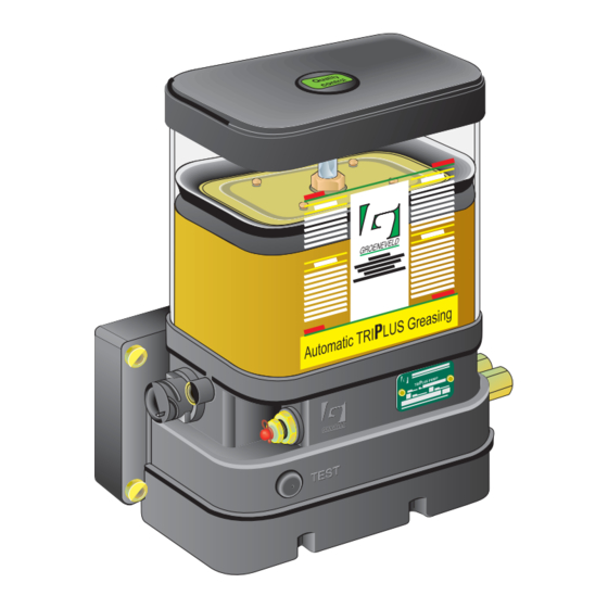
Page 9: Composition Of The Triplus Trailer Pump
Automatic Greasing System TriPlus Trailer Composition of the TriPlus trailer pump trailer The TriPlus pump comprised the following components: Grease reservoir with follower piston. Stirring gear. Plunger pump. Electronic control and monitoring unit with permanent memory. Relief valve with return line to the grease reservoir and electric contact for monitoring purposes by the control unit. -
Page 10: The Intigrated Control And Monitoring Unit
Automatic Greasing System TriPlus Trailer The intigrated control and monitoring unit The control and monitoring unit iniates and controls the greasing cycles of the greasing system. All required system and program parameters, such as at which intervals (number of brake commands or pulses) grease should be applied and with what quanties, are laid down in the control unit. -
Page 11: Safety And Control Features
Automatic Greasing System TriPlus Trailer Safety and control features 2.5.1 Maximum grease pressure A relief valve (fitted with an electrical contact) is installed in the grease channel between the plunger pump and the output port. This relief valve will start to lead the grease back to the reservoir if the maximum grease pressure is exceeded during the pump phase of a greasing cycle. -
Page 12: The Test Pushbutton
Automatic Greasing System TriPlus Trailer The test pushbutton The test pushbutton on the pump unit has two functions: • Performing a test cycle via one of the grease output ports of the pump unit. • Retrieving error messages stored in the memory of the control unit. -
Page 13: The Signal Light
Automatic Greasing System TriPlus Trailer The signal light The driver or operator will be informed about the operation of the greasing system through a signal light which is installed on the dashboard in the cabin. The physical form of the signal light may vary, but it is always installed so that is easily visible. - Page 14 Automatic Greasing System TriPlus Trailer The signal light indicates the fault codes by blinking: The decades of the fault code: long pulses (0,5 seconds) The units of the fault code: short pulses (0,15 seconds) There is a two second pause between successive fault codes. For example, if the fault codes 13 and...
-
Page 15: The Distribution Blocks
Automatic Greasing System TriPlus Trailer The distribution blocks 2.8.1 Properties TriPlus distribution blocks distribute the grease to the various grease points and meter-out the amount of grease that goes to each individual grease point. They do so in a progressive, sequential way. -
Page 16: Principle Of Operation
Automatic Greasing System TriPlus Trailer 2.8.3 Principle of operation Figure 2.6 Principle of operation To operate, progressive distribution blocks need no other energy source than the grease pressure supplied by the pump of the greasing system: The lubricant flows from the input port, via piston 3, through all segments to the left-hand side of piston 1. -
Page 17: Non-Return Valves
Automatic Greasing System TriPlus Trailer 2.8.4 Non-return valves Non-return valves are installed in the outputs of the distribution block to prevent lubricant from flowing back into the distribution block. All output ports to which primary lines are connected or must which are used to interconnect distribution blocks be fitted with non-return valves. -
Page 18: The Gina
Automatic Greasing System TriPlus Trailer The GINA Introduction The GINA ( roeneveld tester for stallation and nalysis) is a programming and read-out device for the digital control unit of the TriPlus automatic greasing system. Figure 3.1 The GINA In the description that follows all screens of the GINA are dealt with in the order in which they have been placed in its menu system. -
Page 19: Connecting The Gina
Automatic Greasing System TriPlus Trailer Connecting the GINA The supply voltage of the control unit to be read or programmed must be available (from the vehicle or an external power supply, if need be). Connect the GINA with the control unit, using the supplied interconnection cable. -
Page 20: Main Menu
Automatic Greasing System TriPlus Trailer This message appears if the control unit is not supported by this GINA: DEVICE NOT SUPPORTED You need another GINA to access this control unit. Main menu main Press < > The main menu contains various data about the GINA and MAIN MENU the control unit that is connected. - Page 21 Automatic Greasing System TriPlus Trailer The screen shows the version number of the software in this INFO GINA. Software-version Prog unit: xxxx p-ui acces p-ui Press <F2> ( The screen shows the identification number of the INFO registered user of this GINA.
- Page 22 Automatic Greasing System TriPlus Trailer The screen shows the hours of the current date and time. TIME You can change this setting with the numeric keys. Confirm Enter hours the new setting with <ENTER>. Press <F2> ( The screen shows the minutes of the current date and time.
-
Page 23: Parameters Timer
Automatic Greasing System TriPlus Trailer Parameters timer The parameters timer menu contains the parameter settings for the grease cycle. You can view and/ or change these parameters, provided you have the correct ‘access level’. parameters Press < > The screen shows the grease output (in cc) of output port 1. - Page 24 Automatic Greasing System TriPlus Trailer The screen shows a filter period, in % of the total pumping PARAMETERS TIMER phase, in which a possible opening of the over-pressure Max release errors relieve valve will be ignored by the program. The maximum...
-
Page 25: Diagnosis Menu
Automatic Greasing System TriPlus Trailer Diagnosis menu diagnosis Press < > The diagnosis menu shows various pieces of information DIAGNOSIS MENU concerning the current status of the greasing system, such as error messages and the status of its input and output signals. - Page 26 Automatic Greasing System TriPlus Trailer The screen shows the number of cycles which are not ERRORS progressed because of the empty reservoir. After the first Empty reservoir empty reservoir warning the control unit calculates how xxxxx many cycles can be progressed with the available grease in end1 eres the reservoir.
- Page 27 Automatic Greasing System TriPlus Trailer The screen shows four "pending errors". DIAGNOSIS (0= did not occur / 1= occurred): Pending errors (2) rdgr relief valve activated during the last pump phase. the drive shaft of pump turns too slowly or not at...
- Page 28 Automatic Greasing System TriPlus Trailer This is the second I/O-screen. It shows the status of various INP/OUTP hh:mm:ss output signals: I/O (2) open load in circuit of electric pump motor. lowl minimum grease level reached in the reservoir. lowl test...
- Page 29 Automatic Greasing System TriPlus Trailer The screen shows the remaining revolutions of the drive VARIABLES hh:mm:ss shaft, after the first empty reservoir warning, until the Remainder cycles empty reserve of grease 400cc (4000 revolutions) is been used. rbrk rrev rerr rcem Press <NEXT>.
- Page 30 Automatic Greasing System TriPlus Trailer DIAGNOSIS MENU pdif hist hist Press <F2> ( The screen shows the total number of correct executed HISTORY greasing cycles. The number of in-correct cycles can be Total cycles found in the error menu. xxxxxxxx...
-
Page 31: Layout Of The Menu System
3.8.1 Used abbreviations Abbreviation Meaning minus (decreasing contrast) plus (increasing contrast) access authorisation level ald (8) authorisation level device (8) (Triplus trailer-version) auto automatic greasing interval expressed in brake commands contr screen contrast d-ac time & date, last access d-ch time &date, last change... - Page 32 Automatic Greasing System TriPlus Trailer Abbreviation Meaning rcel remaining end-switch pulses, to prevent “end-line” errors rcem remaining number of revolutions until the reserve of grease is been used. rdgr relief valve activated during pump phase rdlv grease output per revolution of the pump drive shaft...
-
Page 33: Main Menu
Automatic Greasing System TriPlus Trailer 3.8.2 Main menu MAIN info time contr u-ac d-ac u-ch d-ch p-ui mnth acces year NEXT 3.8.3 Parameters menu PARAMETERS rdlv psdt poct loct end1 NEXT F212157R02 The GINA 33... -
Page 34: Diagnosis Menu
Automatic Greasing System TriPlus Trailer 3.8.4 Diagnosis menu DIAGNOSIS tinfo mode pump rbrk rdgr rrev lowl lamp rerr pdiff hist rcem end1 rcel prno eres lowl srno tbrk test tive rvlv skrv end-1 revol pending error bits (1) pending rdgr... -
Page 35: Designing A System
Automatic Greasing System TriPlus Trailer Designing a system Introduction The following aspects influence the design of a TriPlus greasing system: The number of grease points to be connected and: • The position of the grease points on the vehicle or machine. - Page 36 Automatic Greasing System TriPlus Trailer Table 1: Outputs of doser segments Segment type Output per segment Output with combined (2 outputs) [cc] outputs [cc] 2 x 0,045cc 0,090cc 2 x 0,125cc 0,250cc 2 x 0,200cc 0,400cc Table 2: Internal resistance in a distribution block (bar) Grease T [°C]...
-
Page 37: Method
Automatic Greasing System TriPlus Trailer Method Determine the conditions under which the system must be able to operate. Make a so-called greasing plan. Indicate, in the greasing plan, the grease demand and greasing interval required by each grease point. Compile the greasing points in groups. -
Page 38: Group The Grease Points
Automatic Greasing System TriPlus Trailer 4.3.4 Group the grease points Compile groups of grease points, taking account of the following: • A main distribution block or multiple grease output ports on the TriPlus pump may be utilised. • The maximum and minimum number of doser segments that can be combined in a single distribution block. -
Page 39: Check The Design
Automatic Greasing System TriPlus Trailer 4.3.6 Check the design Before the components of the system are assembled and installed, the projected system should be checked, by calculation, against the operating conditions it was designed for. Will it work under the giving operating conditions? -
Page 40: Installation
Automatic Greasing System TriPlus Trailer Installation Overview Groeneveld To install a TriPlus greasing system the following tasks must be performed: Mounting the pump (including the control unit). Mounting the progressive distribution blocks. Mounting the primary grease lines (between the pump and the distribution blocks and between the distribution blocks themselves). -
Page 41: General Installation Directives
Automatic Greasing System TriPlus Trailer General installation directives Check the contents of the parts kit (using the parts list including in the kit). Before you start installing the greasing system: Check that all grease points are open and furnished with a sufficient amount of grease. If that is not the case, grease the grease points by hand. -
Page 42: Triplus Pump Unit
The TriPlus pump units with 1, 2 or 3 independent grease output ports. • The TriPlus trailer pump unit with 1 grease output port. The TriPlus pump units are usually applied on pulling vehicles (trucks). TheTriPlus trailer pump units are primarily meant for use on pulled vehicles (trailers). -
Page 43: Triplus Distribution Blocks
Automatic Greasing System TriPlus Trailer TriPlus distribution blocks 5.5.1 General The composition of a progressive distribution block is always vehicle/machine- specific. If the distribution blocks are part of an installation kit, the secondary grease lines and the couplings for the primary grease lines (to the pump unit or main distribution block) will, usually, have already been mounted onto the distribution blocks. -
Page 44: Mounting The Distribution Blocks
Automatic Greasing System TriPlus Trailer 5.5.3 Mounting the distribution blocks Determine the location of the distribution block on the vehicle or machine. Consult the specific installation instruction card and/or take account of: • No stresses may be present in the mounted distribution block. It is best to use mounting brackets to install the distribution blocks! •... - Page 45 Automatic Greasing System TriPlus Trailer Removable couplings: a. Clamp the sleeve in a bench vice. b. Turn the line into the sleeve, to end of the sleeve (counter-clockwise!). c. Turn the line backward 1/4 to 1/2 turn. d. Apply oil or grease to the pillar, the sleeve and the inside of the line.
-
Page 46: Secondary Grease Lines And Couplings
Automatic Greasing System TriPlus Trailer Secondary grease lines and couplings 5.7.1 Grease line types The secondary grease lines are the ones between the distribution blocks and the grease points. These grease lines are connected to the grease points with the aid of special couplings. A wide variety of couplings is available. -
Page 47: Mounting The Secondary Lines
Automatic Greasing System TriPlus Trailer 5.7.2 Mounting the secondary lines Take attention at the following points during mounting the secondary grease lines and couplings: • Always make sure the screw threads of the coupling(s) and the grease point are identical. -
Page 48: Electrical Wiring
To prevent damage to the electrical system of the vehicle or machine, the correct fuses must be installed in power supply circuit (+15 and +30). This does not apply to systems with a TriPlus trailer- pump, because those systems make use of the already adequately fused brake-light circuit of the vehicle. -
Page 49: Wiring Diagram
Automatic Greasing System TriPlus Trailer 5.8.4 Wiring diagram Pump unit Revolution sensor Relief valve Test pushbutton Minimum grease level switch Control unit Pump motor End (distribution)-switch Signal light 10. Stoplight 11. 8-Pole connector 12. Battery Figure 5.1 Wiring diagram F212157R02... -
Page 50: Aerating Of The Greasing System
DIAGNOSIS/IO screens 4 and 5, while switching the relevant input signals. ATTENTION If the system has a TriPlus trailer-pump it is required that the brake lights of the vehicle are lit during the test cycle(s), otherwise the pump unit would be without a power supply. -
Page 51: Maintenance
Automatic Greasing System TriPlus Trailer Maintenance General Groeneveld’s The maintenance of TriPlus systems can be combined with the normal maintenance of the vehicle or machine. WARNING If a high-pressure steam/water jet is used to clean the vehicle or machine, the pump unit of the greasing system should not be directly exposed to the jet. -
Page 52: Filling The Grease Reservoir
Automatic Greasing System TriPlus Trailer Filling the grease reservoir When the grease in the reservoir reaches its minimum level, the reservoir needs to be refilled. To facilitate this, the pump unit is fitted with a grease nipple onto which a garage grease pump can be placed. -
Page 53: Fault Finding
Automatic Greasing System TriPlus Trailer Fault finding Problem Cause Solution Signal light does not light-up 1. No supply voltage (+15) on Check the fuse and, if after contact was switched pin 1 or at required, replace the fuse. signal light. - Page 54 Automatic Greasing System TriPlus Trailer Problem Cause Solution All grease points are too dry, Defective pump unit or block- Retrieve the fault code. and a malfunction is indi- age in the system. If “Maximum pressure cated. exceeded” (relief valve opened during a pump phase): 1.
-
Page 55: Technical Data
Automatic Greasing System TriPlus Trailer Technical data TriPlus trailer pump unit Maximum operating pressure : 250bar Operating temperature : -20 ... +85 °C Supply voltage : either 12 or 24 Vdc Rating pump motor (nominal at 20 °C) : 36 W... -
Page 56: Distribution Blocks
Automatic Greasing System TriPlus Trailer Distribution blocks Maximum operating pressure : 250bar Operating temperature : -20 ... +85 °C Minimum number of doser segments : 3 (excluding start and end segments) Maximum number of doser segments : 12 (excl. start and end segments) - Page 58 Groeneveld Transport Efficiency B.V., Stephensonweg 12, 4207 HB Gorinchem, P.O. Box 777, 4200 AT Gorinchem, The Netherlands, Ph : +31 183 641 400, F : +31 183 624 474, http://www.groeneveld-group.com...
Need help?
Do you have a question about the TriPlus Trailer and is the answer not in the manual?
Questions and answers