
Subscribe to Our Youtube Channel
Related Manuals for Groeneveld Twin-3


Summary of Contents for Groeneveld Twin-3
- Page 1 Twin-3 F210613 rev.00 Gebruiksaanwijzing electrische vatpomp User’s Instruction electrical drum pump Your efficiency is our Challenge!
- Page 2 Nederlands ..........6 English.
- Page 3 F210613 rev.00...
- Page 4 F210613 rev.00...
- Page 5 PUMP 2 GND 1 +15 POWER PUMP VAL1 VAL2 TWIN TEST 4 +SL Automatic Greasing System SWITCH F210613 rev.00...
- Page 6 Doseur Secundaire leiding 10. Aansluitkoppeling op het smeerpunt Als een Twin-3 vetsmeersysteem wordt gemonteerd op een voertuig dat bestuurd wordt door een PLC (Programmable Logic Controller), kan de besturing van het Twin-3 vetsmeersysteem eventueel worden overgenomen door die PLC. In dat geval zal de electrische vatpomp worden geleverd zonder besturingseenheid.
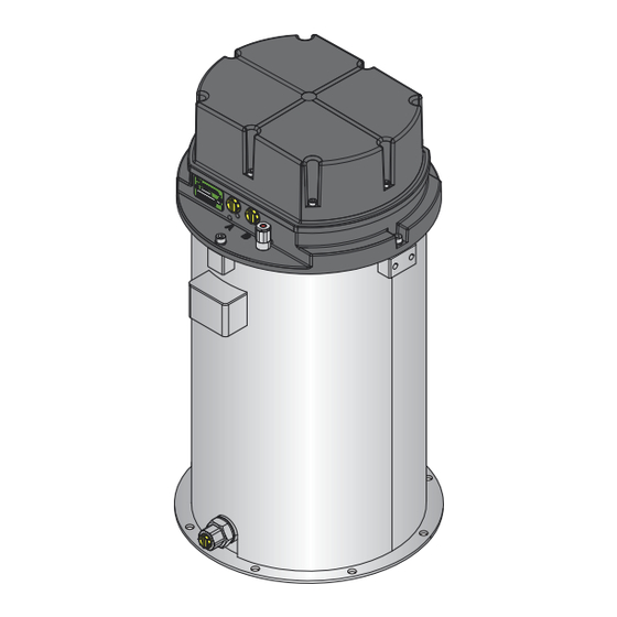
- Page 7 Werking van de Twin-3 elektrische vatpomp (fig. A & B) Het hart van de vatpomp wordt gevormd door een elektrisch aangedreven pompunit die bestaat uit een 5-tal radiaal geplaatste vaste cilinders met zuigers (25). Een elektromotor (19) drijft, via een mechanische overbrenging een as aan met een daarop bevestigd excentriek.
- Page 8 Werking van de testdrukknop (fig. B) Inleiding Om het smeersysteem te testen kunnen twee verschillende testcycli worden uitgevoerd met de testdrukknop (18): de enkele-testcyclus (via de A- of B-vetleiding) de continu-testcyclus (een aantal opeenvolgende smeercycli via de A- en B-vetleiding) Een testcyclus kan alleen worden uitgevoerd als het vetsmeersysteem met de nasmeerfase, de drukafbouwfase of met de pauzefase bezig is.
- Page 9 De continu testcyclus Met een continu-testcyclus kunt u versneld extra vet toevoegen aan de smeerpunten of het smeersysteem ontluchten. LET OP Bij extreem koud weer kan het voorkomen dat het vetsmeersysteem faalt om de continu-testcyclus correct uit te voeren. Gebruik in dit geval de enkele-testcyclus.
- Page 10 Controle van werking van de pomp en 5/2-weg ventiel (fig. A & B) Koppel beide primaire vetleidingen (4 en 5) los van de Twin-3 vat- pomp. LET OP Er kan nog vetdruk in een van deze primaire vetleidingen aanwezig zijn.
- Page 11 Raadpleeg uw vetleverancier of Groeneveld als u een ander type vet wilt gaan gebruiken. Het Twin-3 vetsmeersysteem is ontwikkeld voor gebruik van vetten tot en met NLGI-klasse 2. Welke NLGI-klasse moet worden toegepast, is hoofdzakelijk afhankelijk van de...
- Page 12 Bijvullen van het vet Als het vet in het vat het minimumniveau heeft bereikt, moet het vat worden bijgevuld. Het vat is hiervoor uitgerust met een vulkoppeling (27) waarop een vulpomp kan worden aangesloten. De vulprocedure is als volgt: Pers bij een nieuwe vulpomp (of vulslang) eerst de vulslang vol met vet.
- Page 13 Besturingseenheid Pompconnector Vetdrukschakelaar Extra schakelaar Contactschakelaar Accu Testdrukknop Minimuniveauschakelaar Twin-3 display Foutsignaaluitgang (max. 6W), -31 massa Minimumniveau signaaluitgang (max. 6W), -31 massa Extra in-en uitgangsaansluiting Technische specificaties Afmetingen l x b x h: 340 x 340 x 656 mm Voedingsspanning:...
- Page 14 This User’s Instruction contains a specification of the Twin-3 electric drum pump. This information is intended to give the user an insight into the procedures to be used for the use and maintenance of the Twin-3 electric drum pump. This User’s Instruction also contains the technical specifications of the various components of the Twin-3 electric drum pump.
- Page 15 Operation of the Twin-3 electric drum pump (fig. A & B) The heart of the drum pump is formed by an electric pump unit comprised of 5 fixed cylinders (25) in a radial array. An electric motor (19) connected to the shaft by a mechanical transmission drives the excentric on the shaft.
- Page 16 Operation of the test pushbutton (fig. B) Introduction The test pushbutton (18) is used to start one of two different test cycles to check the performance of the greasing system, i.e.: a single-test cycle (via the A or B grease line). a continuous-test cycle (a number of successive greasing cycles via the A and B grease lines).
- Page 17 The continual-test cycle The continual-test cycle enables you to rapidly supply extra grease to the greasing points or to purge the greasing system. ATTENTION The greasing system may be unable to carry out the continual-test cycle correctly in extremely cold weather. In such situations you should use the single-test cycle.
- Page 18 Inspection of the operation of the pump and the 5/2- way valve (fig. A & B) Disconnect both main greasing lines (4 and 5) from the Twin-3 drum pump. ATTENTION One of these main grease lines may still be under pressure.
- Page 19 Consult your grease supplier or Groeneveld if you wish to change to a different type of grease. The Twin-3 greasing system has been designed for use with greases up to and including NLGI Category 2. The appropriate NLGI category will primarily depend on the temperatures in...
-
Page 20: Cleaning And Maintenance
Topping up the grease The level of grease in the refillable drum must be topped up once the level has fallen to the minimum level. Top up the grease by connecting a filling pump to the filling coupling (27) fitted to the drum. The procedure used to fill the drum is as follows: Begin by pumping the hose of a new filling pump (or filling hose) with grease. -
Page 21: Technical Specifications
Grease pressure switch Command switch Ignition switch Batterie Test pushbutton Minimum level switch Twin-3 display Error signal output (max. 6W), -31 ground Minimum level signal output (max. 6W), -31 ground Additional in- output connection Technical specifications Sizes l x b x h:... - Page 22 Groeneveld Transport Efficiency B.V., Stephensonweg 12, 4207 HB Gorinchem, P.O. Box 777, 4200 AT Gorinchem, The Netherlands, Ph : +31 183 641 400, F : +31 183 624 474, http://www.groeneveld-group.com...
Need help?
Do you have a question about the Twin-3 and is the answer not in the manual?
Questions and answers
on the 3.1 24v twin? hooking up the p0wer to the pump and controller, 24v to the main red then the switched on power ? 12v or 24v to the command signal to the green wire?
To connect power to the pump and controller for the Groeneveld Twin-3 3.1 24V system:
1. Connect the red power wire (no. 1) to pin 1 of the pump connector.
2. Connect the black ground wire (no. 2) to pin 2 of the pump connector.
3. Ensure the battery provides 24V.
4. The controller is connected via additional wiring, including a purple communication wire (no. 6) between the display and pump (pin 6).
Check fuses and wiring for proper function.
This answer is automatically generated