
Related Manuals for GIGAIPC mITX-Q47EA


Summary of Contents for GIGAIPC mITX-Q47EA
-
Page 1: Mitx-Q47Ea Mini-Itx Motherboard
(MQ47EAI-SI) mITX-Q47EA Mini-ITX Motherboard User’s Manual 1st Ed www.gigaipc.com... -
Page 2: Copyright Notice
While reasonable efforts have been made in the preparation of this document to assure its accuracy, GIGAIPC assumes no liabilities resulting from errors or omissions in this document, or from the use of the information contained herein. -
Page 3: Acknowledgement
Core, Atom are trademarks of Intel Corporation • • ITE is a trademark of Integrated Technology Express, Inc. IBM, PC/AT, PS/2, and VGA are trademarks of International Business • Machines Corporation. All other product names or trademarks are properties of their respective owners. www.gigaipc.com... -
Page 4: Packing List
Before setting up your product, please make sure the following items have been shipped: Item Quantity mITX-Q47EA MB SATA power cable I/O Bracket If any of these items are missing or damaged, please contact your distributor or sales representative immediately. -
Page 5: About This Document
(if any), its specifications, dimensions, jumper/ connector settings/definitions, and driver installation instructions (if any), to facilitate users in setting up their product. Users may refer to the GIGAIPC.com for the latest version of this document. www.gigaipc.com... -
Page 6: Safety Precautions
Make sure the device is installed near a power outlet and is easily accessible. 10. Keep this device away from humidity. 11. Place the device on a solid surface during installation to prevent falls 12. Do not cover the openings on the device to ensure optimal heat dissipation. www.gigaipc.com... - Page 7 18. D O N O T L E AV E T H I S D E V I C E I N A N U N C O N T R O L L E D ENVIRONMENT WITH TEMPERATURES BEYOND THE DEVICE’S PERMITTED STORAGE TEMPERATURES (SEE CHAPTER 1) TO PREVENT DAMAGE. www.gigaipc.com...
-
Page 8: Fcc Statement
Il y a un risque d’explosion si la batterie est remplacée de façon incorrecte. Ne la remplacer qu’avec le même modèle ou équivalent recommandé par le constructeur. Recycler les batteries usées en accord avec les instructions du fabricant et les directives gouvernementales de recyclage. www.gigaipc.com... -
Page 9: China Rohs Requirements (Cn)
China RoHS Requirements (CN) 产品中有毒有害物质或元素名称及含量 GIGAIPC Main Board/ Daughter Board/ Backplane 有毒有害物质或元素 部件名称 铅 汞 镉 六价铬 多溴联苯 多溴二苯醚 (Pb) (Hg) (Cd) (Cr(VI)) (PBB) (PBDE) 印刷电路板 及其电 ○ ○ ○ ○ ○ ○ 子组件 外部信号 连接器 ○ ○ ○ ○... -
Page 10: China Rohs Requirement (En)
China RoHS Requirement (EN) Poisonous or Hazardous Substances or Elements in Products GIGAIPC Main Board/ Daughter Board/ Backplane Poisonous or Hazardous Substances or Elements Component Hexavalent Polybrominated Polybrominated Lead Mercury Cadmium Chromium Biphenyls Diphenyl Ethers (Pb) (Hg) (Cd) (Cr(VI)) (PBB) (PBDE) PCB &... -
Page 11: Table Of Contents
Table Contents mITX-Q47EA Mini-ITX Motherboard User’s Manual 1st Ed Copyright Notice ................2 Acknowledgement ............... 3 Packing List ................... 4 About this Document ..............5 Safety Precautions ............... 6 FCC Statement ................8 China RoHS Requirements (CN) ............ 9 China RoHS Requirement (EN) ........... 10 Chapter 1 - Product Specifications Specifications ............... - Page 12 2.2.26 CPU_FAN (CPU FAN Connector) ........47 2.2.27 JCOM1 (COM1 RI# pin RI#/5V/12V Select) ....48 2.2.28 SODIMM1, SODIMM2 (2 x DDR4 SO-DIMM Sockets) ... 49 2.2.29 M2M (M.2 Slot, M-Key, PCIe Gen3 x4, SATA 6Gb/s per slot, Supports NGFF-2280 cards) ........49 www.gigaipc.com...
-
Page 13: Chapter 1 - Product Specifications
Chapter 1 Chapter 1 - Product Specifications www.gigaipc.com... - Page 14 www.gigaipc.com...
-
Page 15: Specifications
Specifications Motherboard mITX-Q47EA (MQ47EAI-SI) Mini-ITX Form Factor 170W x 170D (mm) Support for 10th Generation Intel® Core™ i9/ i7/ i5/ i3 processors, Intel® Pentium®/ Celeron® processors in the LGA1200 package TDP under 65W L3 cache varies with CPU Socket 1 x LGA 1200 Chipset Intel®... - Page 16 Motherboard mITX-Q47EA (MQ47EAI-SI) 1 x 4-pin ATX main power connector 3 x SATA 6Gb/s connectors 2 x SATA power connectors 1 x CPU fan header 1 x System fan header 1 x Front panel header 1 x Front panel audio header 1 x 2W Speaker out header 4 x USB 2.0/1.1 headers...
-
Page 17: Chapter 2 - Hardware Information
Chapter 2 Chapter 2 – Hardware Information www.gigaipc.com... -
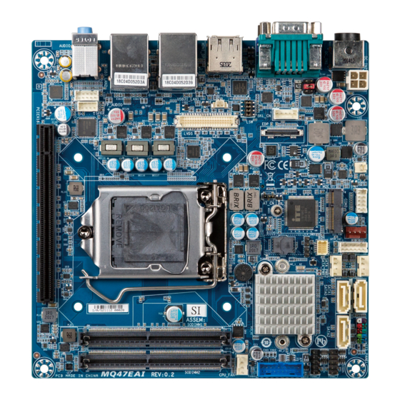
Page 18: Jumpers And Connectors
Jumpers and Connectors www.gigaipc.com... - Page 19 5 HDMI 2 HDMI 2.0 Connector Display Port Connector 6 DP 7 USB31 USB3.2 GEN2x1 Type A Connector x 1 (Red) 8 USB3 USB3.2 GEN1x1 Type A Connector x 3 (Blue) 9 LAN1, LAN2 GbE Eternet LAN port x 2 www.gigaipc.com...
- Page 20 GPIO Connector 27 CLR_CMOS Clear CMOS Jumper 28 SATA_PWR1_2 SATA Power Connector x 2 29 SATA2, 3, 4 SATA 6 Gb/s Connector x 3 30 SYS_PANEL System Panel Header 31 F_USB2_1 USB 2.0 Header 32 F_USB2_2 USB 2.0 Header www.gigaipc.com...
- Page 21 33 F_USB3 USB 3.2 Gen1x1 Header 34 CPU_FAN CPU FAN Connector 35 JCOM1 COM1 RI# pin RI#/5V/12V Select SODIMM1, 2 x DDR4 SO-DIMM Sockets SODIMM2 M.2 Slot, M-Key, PCIe Gen3 x4, SATA 6Gb/s 37 M2M per slot, Supports NGFF-2280 cards www.gigaipc.com...
-
Page 22: Io Connector Information
USB3.2 GEN2x1 Type A Connector x 1 (Red) 7 USB3 USB3.2 GEN1x1 Type A Connector x 3 (Blue) 8 LAN1, LAN2 GbE Eternet LAN port x 2 9 LINE_OUT Line Out port (Green) 10 MIC_IN Mic In port (Pink) www.gigaipc.com... -
Page 23: Dc_In (Dc In Jack 4 Pin Din)
2.2.2 DC_IN (DC In Jack 4 Pin Din) DC In Jack 4 Pin Din www.gigaipc.com... -
Page 24: Dc_In2 (Atx 1X4 Pin Power Connector)
2.2.3 DC_IN2 (ATX 1x4 Pin Power Connector) Pin 1 Power Connector Pin No. Definition DC IN DC IN www.gigaipc.com... -
Page 25: Cpu Socket (Lga 1200 Socket)
2.2.4 CPU Socket (LGA 1200 Socket) Pin 1 www.gigaipc.com... -
Page 26: Bkl_Cn (Back Light Brightness Control Connector)
2.2.5 BKL_CN (Back Light Brightness Control Connector) Pin 1 Back Light Brightness Control Pin No. Definition Connector Backlight enable www.gigaipc.com... -
Page 27: Edp (Embedded Display Port Connector)
2.2.6 EDP (Embedded Display Port connector) Pin 1 Embedded Display Port connector Pin No. Definition Pin No. Definition Hot Plug TX0n Detect Backlight TX0p Enable Backlight TX1n controll TX1p 3.3V TX2n 3.3V TX2p 3.3V 3.3V TX3n TX3p AUXn AUXp www.gigaipc.com... -
Page 28: Lsw (Lvds Resolution Jumper)
18bit 24bit Connector PN Vendor 1400 x 1024 x 768 1050 222-97-04GBE1 PINREX 24bit 24bit 1024 x 600 1600 x 900 18bit 24bit 1280 x 800 1680 x 1050 18bit 24bit 1600 x 1280 x 960 1200 18bit 24bit www.gigaipc.com... -
Page 29: Battery (Battery Connector)
2.2.8 Battery (Battery Connector) Pin 1 Battery Connector Pin No. Definition www.gigaipc.com... -
Page 30: Lvds (Lvds Connector)
But below model no need to add. SPED0 A0~A3 is odd channel 0~3, A4~A7 is ev en channel. Note: *The LVDS output connector of the unit is only intended to be CLK2+ connected to an UL/IEC/EN approval CLK1+ equipment with fire enclosure. CLK2- CLK1- www.gigaipc.com... -
Page 31: Fp_Audio (Front Panel Audio Header)
2.2.10 FP_Audio (Front Panel Audio Header) Pin 1 Front Audio Connector Definition Pin Definition MIC-LEFT JACKSENCE DELTECT MIC-RIGHT DELTECT LINE-LEFT LINE-RIGHT www.gigaipc.com... -
Page 32: Spkr (Speaker Out Connector)
2.2.11 SPKR (Speaker Out Connector) Pin 1 Speaker Out Connector Pin No. Definition SPEAKER L+ SPEAKER L- SPEAKER R- SPEAKER R+ www.gigaipc.com... -
Page 33: Pciex16 (1 X Pcie X16 (Gen3 X16 Bus) Slot)
2.2.12 PCIEX16 (1 x PCIe x16 (Gen3 x16 Bus) Slot) www.gigaipc.com... -
Page 34: Atx_Ctl (Atx Control Header, Support Ps-On Signal Of Power Supply Unit)
2.2.13 ATX_CTL (ATX Control Header, Support PS-ON Signal of Power Supply Unit) Pin 1 ATX Control Header Pin No. Definition PSON# www.gigaipc.com... -
Page 35: Com2 (Rs232 Seriel Port Header)
2.2.14 COM2 (RS232 Seriel Port Header) Pin 1 COM 2 Header Pin No. Definition www.gigaipc.com... -
Page 36: M2E (M.2 Slot, E-Key, Supports Ngff-2230)
2.2.15 M2E (M.2 Slot, E-Key, Supports NGFF-2230) www.gigaipc.com... -
Page 37: At_Cn (At/Atx Power Mode Select Jumper)
2.2.16 AT_CN (AT/ATX power mode select jumper) Pin 1 AT/ATX power mode select jumper Connector PN Vendor PH03N33BAAA00 HORNGTONG Pin No. Definition AT MODE Detect ATX MODE Jumper setting 1-2 Close : AT mode. 2-3 Close : ATX mode.(Default setting) www.gigaipc.com... -
Page 38: Sys_Fan (System Fan Connector)
2.2.17 SYS_FAN (System Fan Connector) Pin 1 System FAN Pin No. Definition Sense www.gigaipc.com... -
Page 39: Gpio_Cnt (Gpio Connector)
2.2.18 GPIO_CNT (GPIO Connector) Pin 1 GPIO Connector Pin No. Definition GPIO-output_1 GPIO-input_1 GPIO-output_2 GPIO-input_2 GPIO-output_3 GPIO-input_3 GPIO-output_4 GPIO-input_4 SMBus Clock SMBus DATA www.gigaipc.com... -
Page 40: Clr_Cmos (Clear Cmos Jumper)
2.2.19 CLR_CMOS (Clear CMOS Jumper) Pin 1 Clear COMS Jumper Pin No. Definition Clear CMOS Open: Normal Operation (Default setting) Close: Clear COMS data. www.gigaipc.com... -
Page 41: Sata_Pwr (Sata Power Connector X 2)
2.2.20 SATA_PWR (SATA Power Connector x 2) Pin 1 SATA Power Connector Pin No. Definition www.gigaipc.com... -
Page 42: Sata2, 3, 4 (Sata 6 Gb/S Connector X 3)
2.2.21 SATA2, 3, 4 (SATA 6 Gb/s Connector x 3) SATA 2 SATA 3 SATA 4 SATA 6GB/S Connector Pin No. Definition SATA 2 SATA 3 SATA 4 www.gigaipc.com... -
Page 43: Sys_Panel (System Panel Header)
2.2.22 SYS_PANEL (System Panel Header) Pin 1 System Panel Header Pin No. Definition HD-P MPD-P HD-N MPD-N POWER-ON Reset Reserved www.gigaipc.com... -
Page 44: F_Usb2_1 (Usb 2.0 Header)
2.2.23 F_USB2_1 (USB 2.0 Header) Pin 1 USB 2.0 Header Pin No. Definition No Pin www.gigaipc.com... -
Page 45: F_Usb2_2 (Usb 2.0 Header)
2.2.24 F_USB2_2 (USB 2.0 Header) Pin 1 USB 2.0 Header Pin No. Definition No Pin www.gigaipc.com... -
Page 46: F_Usb3 (Usb 3.2 Gen1X1 Header)
2.2.25 F_USB3 (USB 3.2 Gen1x1 Header) Pin 1 USB 3.2 Gen1x1 Header Pin No. Definition TX2p TX2n Pin No. Definition RX2p RX2n RX1n RX1p TX1n TX1p www.gigaipc.com... -
Page 47: Cpu_Fan (Cpu Fan Connector)
2.2.26 CPU_FAN (CPU FAN Connector) Pin 1 CPU Fan Connector Pin No. Definition Sense www.gigaipc.com... -
Page 48: Jcom1 (Com1 Ri# Pin Ri#/5V/12V Select)
2.2.27 JCOM1 (COM1 RI# pin RI#/5V/12V Select) Pin 1 JCOM1 Jumper Select Connector PN Vendor 220-97-03GB01 PINREX 1-2 Close: PH06N53BAZ000 HORNGTONG 5V (Power COM) 3-4 Close: RI (Stand COM) 5-6 Close: 12V (Power COM) www.gigaipc.com... -
Page 49: Sodimm1, Sodimm2 (2 X Ddr4 So-Dimm Sockets)
2.2.28 SODIMM1, SODIMM2 (2 x DDR4 SO-DIMM Sockets) 2.2.29 M2M (M.2 Slot, M-Key, PCIe Gen3 x4, SATA 6Gb/s per slot, Supports NGFF-2280 cards) www.gigaipc.com...
Need help?
Do you have a question about the mITX-Q47EA and is the answer not in the manual?
Questions and answers