Table of Contents
Advertisement
Quick Links
Advertisement
Table of Contents

Subscribe to Our Youtube Channel
Related Manuals for Belden Grass Valley NV9603A


Summary of Contents for Belden Grass Valley NV9603A
- Page 1 NV9603A NV9000 Control Panel User’s Guide UG0041-01 14 Nov 2014...
- Page 2 Copyright & Trademark Notice Copyright © 2014 Grass Valley. All rights reserved. Belden, Belden Sending All The Right Signals, and the Belden logo are trademarks or registered trademarks of Belden Inc. or its affiliated companies in the United States and other jurisdictions.
- Page 3 NV9603A User’s Guide Change History Rev. Date Description Approved 05 Nov 10 17286 Initial release. D. Cox 14 Nov 14 18848 Reformatted. D.Cox Safety Compliance FCC Statement This equipment has been tested and found to comply with the limits for a Class A digital device, pursuant to part 15 of the FCC Rules.
- Page 4 Restriction on Hazardous Substances (RoHs) Grass Valley is in compliance with EU Directive RoHS 2002/95/EC governing the restricted use of certain hazardous substances and materials in products and in our manufacturing processes. Grass Valley has a substantial program in place for RoHS compliance that includes significant investment in our manufacturing process, and a migration of Grass Valley product electronic components and structural materials to RoHS compliance.
- Page 5 NV9603A User’s Guide General Warnings A warning indicates a possible hazard to personnel which may cause injury or death. Observe the following general warnings when using or working on this equipment: • Heed all warnings on the unit and in the operating instructions. •...
-
Page 7: Table Of Contents
Table of Contents 1 Preface ..........1 Chapter Structure . - Page 8 Table of Contents 5 Operation ..........25 Summary .
- Page 9 NV9603A User’s Guide Menu Mode ................. . . 39 Panel ID .
- Page 10 Table of Contents...
-
Page 11: Preface
Preface Chapter 1 is an introduction to the NV9603A User’s Guide. Topics Chapter Structure ............... . . 1 The PDF Document . -
Page 12: Terms, Conventions And Abbreviations
Preface Terms, Conventions and Abbreviations Use the ‘First Page’ , ‘Previous Page’ , and ‘Next Page’ , and ‘Last Page’ buttons to go to the first, previous, next, or last page within a PDF file. Note To display the navigation buttons, right-click the Tool Bar area, and check ‘Navigation’ . •... -
Page 13: Introduction
Introduction Chapter 2 provides a functional description of the NV9603A. Topics Summary ................. 3 Panel Organization . -
Page 14: Panel Organization
Introduction Panel Organization At the rear are power, serial, and network connectors: Power (AC) Ethernet Serial port (RS-232) Fig. 2-2: NV9603A Rear The ports labeled 10base2 and RS-422 are non-operational and are covered. Only the serial port and the Ethernet port are available. ... -
Page 15: Flags
NV9603A User’s Guide • Destination. The ‘Dest’ field shows the current destination. The ‘Status’ , ‘Preset’ , and ‘Dest’ fields can show either names belonging to a name set or system names depending on (1) the state of the ‘Name Set Toggle’ button (if the panel has one), (2) the default name set (3) the existence of name sets in the NV9000 configuration. - Page 16 Introduction Other NV9603A Functions...
-
Page 17: Installation
Installation Chapter 3 provides installation and connection instructions. Chapter 3 provides installation and connection instructions. Topics Topics Package Contents Package Contents ............... . . 7 . -
Page 18: Installation
Installation Installation Installation Follow these steps to install a NV9603A control panel: 1 Mount, and secure, the panel in the rack. The NV9603A is designed to mount in a standard 19” rack. Rack-mounting is not a require- ment. 2 We assume that you have an Ethernet switch connected to the “Panel and Router Network” port of your system controller. -
Page 19: Testing
NV9603A User’s Guide 3 The panel displays a confirmation message: 0 C a n c e l S a v e Press the left-most button to cancel your entry; press the button to the right of it to save your entry. 4 Press the setup button once again and continue to press the setup button until the panel displays ‘ACQ IP’... - Page 20 Installation Testing...
-
Page 21: Configuration
Configuration Chapter 4 provides configuration instructions for the NV9603A. Topics Summary ................11 Adding a Panel to an NV9000 Configuration . - Page 22 Configuration Adding a Panel to an NV9000 Configuration After launching NV9000-SE Utilities, choose ‘Control Panels’ from the Configuration pane in the navigation area. The ‘Control Panels’ configuration page appears: Click ‘Add Control Panel’ at the bottom of the configuration page. The ‘Add Control Panel’ page appears: Choose “NV9603”...
- Page 23 NV9603A User’s Guide In the first and third cases, you will create a new configuration file whose name you designate. .603 The file extension for an NV9603A configuration file is . Click ‘Next’ or ‘Finish’ to proceed. Click ‘Previous’ to go back the previous page. Click ‘Cancel’ to terminate the entry operation. ...
-
Page 24: Nv9603A Panel Configuration Page
Configuration NV9603A Panel Configuration Page NV9603A Panel Configuration Page This is the default NV9603A panel configuration page in NV9000-SE Utilities: Panel Image: Button Definition Section Panel Options Fig. 4-1: NV9603A Configuration Page (Default) After you configure buttons the appearance of the panel buttons will have changed. The panel buttons on this page will show legends, determined from the button type assigned to the button. -
Page 25: Configuration Tasks
NV9603A User’s Guide Configuration Tasks The person configuring an NV9603A panel will want to consider how best to use the buttons to support the devices and routers in the router control system at hand. Trade-offs must be made. In support of that effort, the configurer will do the following: •... - Page 26 Configuration Panel Options These are its drop-down menu options: Release Mode Normal Release This panel can release “locks” and “protects” set by the designated user (at this panel or any other panel). Force Release This panel can release locks and protects set by any user. Default None After a reset, the panel has no default destination and displays no...
-
Page 27: Checkbox Options
NV9603A User’s Guide Checkbox Options The checkbox options section is just below the panel options section, enclosed in the same region: A check in the box enables the option. Clearing the checkbox disables the option. By default, all the check box options are clear. The following items are the checkbox options: •... -
Page 28: Button Definitions
Configuration Button Definitions Button Definitions There are three classes of button functions: • Dedicated functions, such as ‘Default State’ or ‘Chop’ . • Variable functions, such as ‘Source’ or ‘Destination’ . • Special functions, such as ‘Menu’ and ‘Salvo’ . Note During configuration, certain button fields contain a colon (:) and number after the data in the field. -
Page 29: Button Types
NV9603A User’s Guide Button Types These are the button types available for NV9603A configurations: Type Description Broadcast On the data (machine control) level, the button enables a broadcast take to an additional controlled device, after a broadcast route has been initiated with a “source is master”... - Page 30 Configuration Button Definitions Type Description Destination The button sets or removes a “lock” on the current destination device. The lock Lock can be removed only by the user (at this panel or at another) that originally set the lock, or by a panel that has “Force Release” enabled. The button definition has no fields to configure.
- Page 31 NV9603A User’s Guide Type Description Level The button selects a level. The button definition has one field to configure: the level. (Do not choose ‘None’ for the level.) Your panel can have multiple level buttons, one for each level you want the operator to control.
- Page 32 Configuration Button Definitions Type Description Page Down The button scrolls down through the device list of the currently selected category. The device selected appears in the ‘Preset’ field of the display. The term “page” does not have any meaning here. ‘Page Down’...
- Page 33 NV9603A User’s Guide Type Description Source The button selects a source. The source name appears in the ‘Preset’ display. When you assign a source button, two drop-down menus appear: ‘Source Device 1’ and ‘Source Device 2’ . These correspond to two sets of sources. If there is a ‘Source Shift’...
-
Page 34: Single-Destination Configuration
Configuration Single-Destination Configuration Single-Destination Configuration It is possible to configure the panel for single-destination operation. The default destination (a panel option) is the single destination. There would be no destination buttons supporting other destinations. -
Page 35: Operation
Operation Chapter 5 provides operating instructions for the NV9603A control panel. Topics Summary ................25 Operating Concepts . -
Page 36: Single-Destination Operation
Operation Summary Takes are all level unless your panel has level buttons. If your panel has level buttons, you can select the level(s) on which the take is to occur. The sources of levels not selected remain unchanged. Single-Destination Operation Your panel might have been configured to have a single destination. -
Page 37: Operating Concepts
NV9603A User’s Guide Operating Concepts Source Shift and Destination Shift Each source button can represent two sources. A ‘Source Shift’ button selects which of the two sources the button will select. (The concept is similar to the shift key or the ‘caps lock’ key on a keyboard.) A source shift button is a toggle: it is low-tally when it has enabled the first source. -
Page 38: Making A Category Selection
Operation Operating Concepts Making a Category Selection 1 Put the panel in source mode or destination mode as required. (Note: you must select a des- tination first, then the source, then press ‘Take’— unless your panel is a single-destination panel where the destination is always pre-selected.) 2 Press a category button that will initiate a category selection. -
Page 39: Level Selection
NV9603A User’s Guide It is not possible to take different sources to the destination on the same level. For instance, you cannot take SD from two different sources. The outcome would be noise even if you could do it. (That is because routers are not mixers.) Level Selection If your panel has level buttons, you can select or deselect levels. -
Page 40: Chop
Operation Operating Concepts • Select a destination category and initiate device selection for that category. • During the process of device selection, add a suffix to the pending device name. A category button can provide any or all of these functions. A typical NV9603A configuration has a “keypad”... -
Page 41: Destination Lock
NV9603A User’s Guide Destination Lock This button is a toggle that sets or clears a lock on the current destination. The lock can be removed at the panel that originally set the lock, at a panel that has the same user ID, or by a forced release at any panel. -
Page 42: Destination Shift
Operation Operating Concepts Destination Shift The ‘Destination Shift’ button toggles between the first and second sets of destinations. The button affects the operation of any destination button. Free Source The button selects a pre-defined phantom device that can be used to release or “free” devices on the data (machine control) level. -
Page 43: Panel Lock
NV9603A User’s Guide • Scrolling salvos in salvo mode: ‘Page Down’ moves to the salvo with the next lower index in the panel’s salvo list. (It is expected that if the panel has a salvo button, the NV9000 system also has a salvo list.) Scrolling salvos is not subject to the “continuous scrolling”... -
Page 44: Source
Operation Operating Concepts Source The button selects a source. The source name appears in the ‘Status’ display. A source button represents two sources. The source selected when you press the button is affected by whether your panel has a ‘Source Shift’ button and its state: whether it is selected or not. -
Page 45: Take
NV9603A User’s Guide Take In normal mode, a take button routes the preset source to the selected destination on selected level or levels. In salvo mode, a take button executes a selected salvo. A take button is disabled (and dark) until it becomes possible for the operator to execute a take. Undefined An undefined button cannot be used and appears dark (unlit) on the panel. -
Page 46: Takes
Operation Operating Concepts Use this same method to protect or unprotect selected levels, using a ‘Destination Protect’ button instead. Note that lock buttons are toggles. Therefore, if you select some levels that are already locked and some that are unlocked, pressing the lock button will invert their status. Locked levels become unlocked and those that were unlocked become unlocked. -
Page 47: Broadcast Routes
NV9603A User’s Guide Broadcast Routes It is easy to route a source to multiple destinations for audio and video routers. You place the panel in hold mode with the hold button. In contrast, machine control routes are typically point-to-point. Therefore, to control multiple machines requires that you perform a “broadcast”... -
Page 48: Data Routing
Operation Operating Concepts Data Routing There are 3 data routing options that affect sources and destinations that have a machine control level (i.e., a data level). These options govern what happens when a source or destina- tion device is to be used. Automatic Data Routing A take involving a machine control level occurs automatically, without intervention, regardless of who is using a device. -
Page 49: Salvo Mode
NV9603A User’s Guide Follow these steps: 1 Press a destination button. The ‘Destination’ field of the display shows the destination you chose. Scroll to the correct page if necessary. 2 Optionally press ‘Source Shift’ to toggle between the sets of sources. 3 Press a source button. -
Page 50: Panel Id
Operation Menu Mode Panel ID The panel ID submenu appears first when you press the menu button: P a n e l I D Menu button, in _ _ _ _ 6 0 3 1 these examples The panel now allows you to enter the panel ID using buttons at the left that function as a numeric keypad. -
Page 51: Software Versions
NV9603A User’s Guide Software Versions The fifth submenu displays the software version: S V 0 9 2 1 - 0 The sixth submenu displays the boot version: B S V 0 9 9 4 - 0 1 0 0 0 0 The seventh submenu displays the application version: A S V 0 0 0 0 - 0 0 0 0 0 0... -
Page 52: Setup Mode
Operation Setup Mode Setup Mode Setup mode occurs when the NV9603A is disconnected from its network and is freshly powered up. In setup mode, you can set or change the panel ID, identify the software version, and perform a test of the panel’s buttons. It is in setup mode that you must initially set the panel ID. ... - Page 53 NV9603A User’s Guide Press the setup button to proceed to the pixel test: In this test, all the dots in each character of the 2 displays should be illuminated. Press the setup button to proceed to the color test. This test has 4 parts: •...
- Page 54 Operation Setup Mode...
-
Page 55: Technical Details
Technical Details Chapter 6 provides electrical and mechanical specifications for the NV9603A. Topics Power Specifications ..............45 NV9603A Specifications . -
Page 56: Environmental Specifications
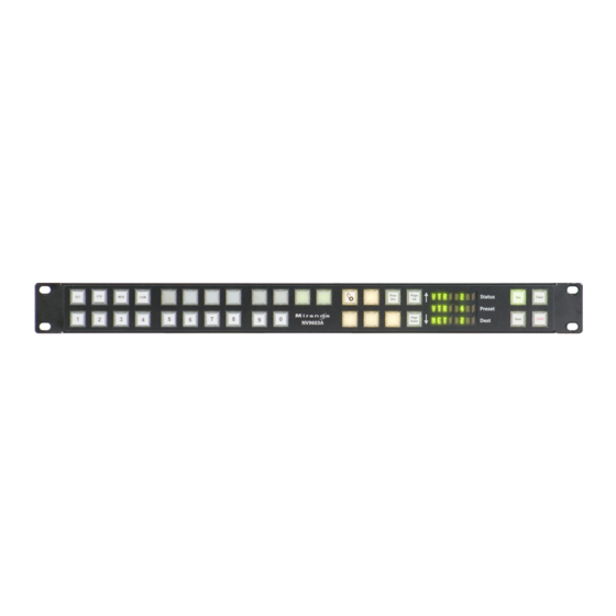
Technical Details Environmental Specifications The RS-232 connector has this pinout: n.c. n.c. n.c. n.c. n.c. n.c. Pins 1, 4, and 6 are tied together and pins 7 and 8 are tied together. None of those pins are connected to any circuitry. Environmental Specifications NV9603A Environmental Specifications Specification... - Page 57 NV9603A User’s Guide Fig. 6-1: Front View of the NV9603A...
- Page 58 Technical Details Drawings Fig. 6-2: Top, and Rear Views of the NV9603A...
-
Page 59: Glossary
Glossary AES/EBU (Audio Engineering Society/European Broadcasting Union). AES and EBU are standards organizations. Breakaway A condition where a destination has multiple sources on different levels. Category A category represents a set of devices. (The concept of categories exists to make it easier to select devices at a control panel.) A category can contain sources, destinations, or devices that are both sources and destinations. - Page 60 Glossary or more input ports. A destination is a device that is connected to one or more output ports. An example of such a device would be a monitor. A device can be both a source and destination. An example of such a device is a VTR. System The system administrator is the person responsible for installing, configuring, and maintaining a administrator...
-
Page 61: Index
Index menu ......5, 21, 26, 29, 32, 39 name set toggle ......5, 21, 32, 36 next . - Page 62 Index 4, Configuration ....... . . 11 Destination (display) ......5, 30 5, Operation .
- Page 63 NV9603A User’s Guide NV9603A, rear view ......48 NV9603A, rear, photo ......4 NV9603A, top view .
- Page 64 Index acquiring IP address ......8–9 locating network ....... . . 9 no server .
- Page 65 NV9603A User’s Guide about PDF documents ......1 Software, configuration ....... 2 chapter structure .
- Page 66 Index Virtual levels ........49–50 Undefined (button) .
-
Page 67: Contact Us
Contact Us Grass Valley Technical Support For technical assistance, please contact the Grass Valley Technical Support center nearest you: Americas Asia Office hours: 9:00 a.m. – 9:00 p.m. (EST) Office hours: 9:30 a.m. – 6:00 p.m. (GMT+8) Telephone: +1-800-547-8949 Telephone: +852 2539 6987 Fax: +1-514-335-1614...
Need help?
Do you have a question about the Grass Valley NV9603A and is the answer not in the manual?
Questions and answers