Table of Contents
Advertisement
Quick Links
Advertisement
Table of Contents

Related Manuals for Belden Grass Valley NV9648


Summary of Contents for Belden Grass Valley NV9648
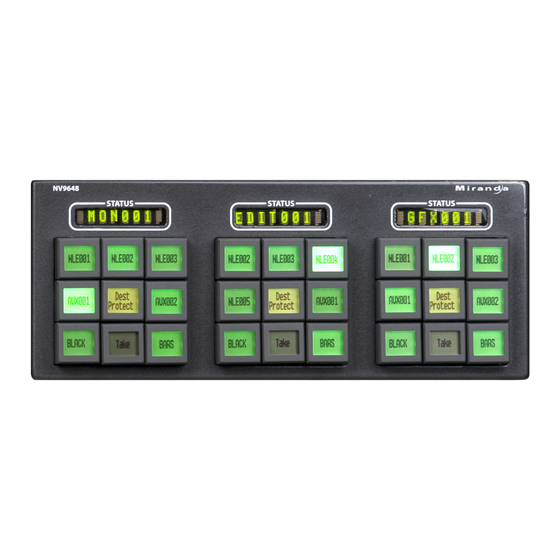
- Page 1 NV9648 NV9000 Control Panel User’s Guide UG0075-01 20 Nov 2014...
- Page 2 Copyright & Trademark Notice Copyright © 2014 Grass Valley. All rights reserved. Belden, Belden Sending All The Right Signals, and the Belden logo are trademarks or registered trademarks of Belden Inc. or its affiliated companies in the United States and other jurisdictions.
- Page 3 NV9648 User’s Guide Change History Rev. Date Description Approved 24 Apr 13 18826 Initial release D.Cox 20 Nov 14 19357 New format. Added Korean compliance statement. D.Cox Client assignments (in server mode) preserved over power cycles. Safety Compliance Korean Compliance (KCC) Statement KCC-REM-XEI-NV8500 급...
- Page 4 Important Safeguards and Notices This section provides important safety guidelines for operators and service personnel. Specific warnings and cautions appear throughout the manual where they apply. Please read and follow this important information, especially those instructions related to the risk of electric shock or injury to persons.
- Page 5 NV9648 User’s Guide Symbols and Their Meanings The lightning flash with arrowhead symbol within an equilateral triangle alerts the user to the presence of dangerous voltages within the product’s enclosure that may be of sufficient magnitude to constitute a risk of electric shock to persons. The exclamation point within an equilateral triangle alerts the user to the presence of important operating and maintenance/service instructions.
- Page 6 • To avoid fire hazard, use only the specified fuse(s) with the correct type number, voltage and current ratings as referenced in the appropriate locations in the service instruc- tions or on the equipment. Always refer fuse replacements to qualified service person- nel.
-
Page 7: Table Of Contents
Table of Contents 1 Preface ..........1 Chapter Structure . - Page 8 Table of Contents Configuration Page for LCD XY/MD Mode ..........25 Characteristics of LCD XY/MD Mode.
- Page 9 NV9648 User’s Guide Button Functions ................56 Buttons for the Client Model .
- Page 10 Table of Contents Setup Mode ................. . . 71 Panel ID.
-
Page 11: Preface
Preface Chapter 1 is an introduction to the NV9648 User’s Guide. Topics Chapter Structure ............... . . 1 The PDF Document . -
Page 12: Terms, Conventions And Abbreviations
Preface Terms, Conventions and Abbreviations • Use the ‘First Page’ , ‘Previous Page’ , and ‘Next Page’ , and ‘Last Page’ buttons to go to the first, previous, next, or last page within a PDF file. Note To display the navigation buttons, right-click the Tool Bar area, and check ‘Navigation’ . •... -
Page 13: Introduction
Introduction Chapter 2 provides a functional description of the NV9648. Topics Summary ................. 3 Function Buttons and Displays . -
Page 14: Function Buttons And Displays
Introduction Function Buttons and Displays The NV9648 has 3 very different operating modes (or behavioral models): • ‘Panel Client’ mode. For brevity, we can call this “client” mode. When the panel is in “client” mode, it operates in conjunction with an NV9649 and other NV9648s. -
Page 15: Tally Interface
NV9648 User’s Guide Tally Interface At the rear of the panel is a DB25 connector that provides 8 tally inputs and 4 tally outputs. (The outputs are solid state relay outputs.) Both inputs and outputs are optically isolated. During configuration, you can construct Boolean logic that switches the outputs on or off. The terms of the logic expressions are states of the source and destination devices, etc., controlled by the NV9000 control system. -
Page 16: Saved Client Assignments
Introduction Modes of Operation Here is an example of a system with an NV9649 and 7 NV9648 clients: NV9649 (1) NV9648 (7) 3 Panel Sections (7x) In this example, there are 21 control sections in addition to the controls of the NV9649. At any moment, the operator can route to 21 destinations. -
Page 17: Lcd Min Xy/Md' Mode
NV9648 User’s Guide ‘LCD Min XY/MD’ Mode When the panel is in LCD XY/MD mode, the panel also operates standalone, not requiring the presence of an NV9649, and has a moderately richer function set. The panel’s buttons can be used in a hierarchical fashion: pressing a ‘navigation’ button causes the panel to display a new set of configured button functions, called a “button page. - Page 18 Introduction Other NV9648 Functions Most of these capabilities are available only under the ‘LCD Min XY/MD’ behavioral model.
-
Page 19: Installation
Installation Chapter 3 provides a functional description of the NV9648. Topics Package Contents ............... . . 9 Installation . -
Page 20: Installation
Installation Installation Installation Follow these steps to install a NV9648 control panel: 1 Mount, and secure, the panel(s) in the rack. The NV9648 is designed to mount in a 19” rack. Rack-mounting is not a requirement. The NV9648 is a 2RU half-width panel: you can install two of them side by side in a rack. Rack mounting (either one or two NV9648s) requires a rack mounting bracket such as the one in Grass Valley’s NV9649-48-RMK (rack-mounting kit). -
Page 21: Installing Software And Documentation
NV9648 User’s Guide A second power connection is for redundancy only (protection against failure) and is not a requirement for operation. Refer to Power Specifications on page 81 for details on the PS0001 power supply. See also Power Cord Retention on page 87. -
Page 22: Testing
Installation Testing 3 The panel ID menu has a numeric “keypad” with which you can enter a new panel ID: NV9648 P a n e l I D 6 4 8 1 PANEL ID PANEL ID 123 123 CLEAR CLEAR SAVE SAVE EXIT... - Page 23 NV9648 User’s Guide 3 Is the NV9000 system controller actually running? With the typical noise levels in a facility, it can sometimes be difficult to tell. Use the ‘System’ pages of NV9000-SE Utilities to make the determination. 4 Is NV9000-SE Utilities installed and operating? If so, can you upload a configuration to the specified panel? 5 Does the configuration actually work? Is it useful? Can the operator perform takes and per- form other operations?
- Page 24 Installation Testing...
-
Page 25: Configuration
Configuration Chapter 4 provides configuration instructions for the NV9648. Topics Summary ................15 Adding a Panel to an NV9000 Configuration . -
Page 26: Adding A Panel To An Nv9000 Configuration
Configuration Adding a Panel to an NV9000 Configuration The operator can switch the panel between “X-Y mode” and multi-destination (MD) mode. In X-Y mode, the operator can perform takes (and locks) on individually selected levels. In MD mode, takes occur on all levels, but the operator can perform takes to multiple destinations simultaneously. - Page 27 NV9648 User’s Guide The ‘Add Control Panel’ page appears: Choose “NV9648” from the ‘Type’ field. In the ID field, enter the panel ID you assigned to the panel while it was in setup mode. Give a name to the panel in the name field and select a user. When you are creating a panel configuration you have 3 options.
-
Page 28: Nv9648 Panel Configuration Page(S)
Configuration NV9648 Panel Configuration Page(s) Return to the ‘Control Panels’ page to view your new entry. To edit an NV9648 configuration, either double-click its list entry or select the entry and then click ‘Edit Selected Control Panels’: You will then see the panel configuration page for the selected NV9648. The following section of this guide discusses using the panel configuration page in which you configure an NV9648. -
Page 29: Gpio Section
NV9648 User’s Guide GPIO Section In this section, configurers may define GPIO logic. The control panel has a rear connector that provides 4 relay outputs and 8 optically isolated inputs. The section has two parts: inputs and outputs. By clicking on one of the input or output buttons, you can configure the input or output. (The NV9648 has no actual tally buttons. -
Page 30: Configuration Page For Client Mode
Configuration NV9648 Panel Configuration Page(s) Configuration Page for Client Mode This is a sample NV9648 panel configuration page for client mode: Panel Image: Button Definition Section Panel Options GPIO Definitions Fig. 4-1: NV9648 Configuration Page (in Client Mode) There are 5 button function types for a panel in client mode: Destination Lock Destination Protect Quick Source... -
Page 31: Client Mode Panel Options
NV9648 User’s Guide Client Mode Panel Options In a client mode configuration, the panel options section, at the right of the configuration page, has 6 drop-down menus (and no checkbox options). These are the drop-down menus: By making a selection in the behavioral model field, you change the content of the entire configuration page, including the set of panel options. -
Page 32: Configuration Page For Standalone Mode
Configuration NV9648 Panel Configuration Page(s) Master Panel ‹panel ID› The NV9648 in client mode must be associated with the NV9649 server identified by ‹panel ID›. Selecting a panel ID in this field presupposes that you have previ- ously defined an NV9649 configuration (even if it is incomplete at the time you are configuring the NV9648). -
Page 33: Standalone Panel Options
NV9648 User’s Guide Each section’s display shows its own destination. (The display reads “NO DEST” if no destination has been selected. Standalone Panel Options In a standalone configuration, the panel options section, at the right of the configuration page, has 6 drop-down menus (and no checkbox options): By making a selection in the behavioral model field, you change the content of the entire configuration, including the set of panel options. - Page 34 Configuration NV9648 Panel Configuration Page(s) Preset Monitor None The preset source video is not sent to a monitor. ‹device› The preset source video for the selected destination appears on the specified monitor (device). Status Monitor None The current source video is not sent to a monitor. ‹device›...
-
Page 35: Configuration Page For Lcd Xy/Md Mode
NV9648 User’s Guide Configuration Page for LCD XY/MD Mode This is a sample NV9648 panel configuration page for XY/MD mode: Panel Image: Button Definition Section Panel Options Page Table GPIO Defi- nitions Fig. 4-3: NV9648 Configuration Page (in XY/MD Mode) There are 21 button function types for a panel in XY/MD mode: Back Category... -
Page 36: Characteristics Of Lcd Xy/Md Mode
Configuration NV9648 Panel Configuration Page(s) Characteristics of LCD XY/MD Mode The panel in LCD XY/MD mode has a more extensive function set than panels in client mode or standalone mode. In LCD XY/MD mode too, the panel does not require the presence of an NV9649. -
Page 37: Panel Options
NV9648 User’s Guide Panel Options The panel options section, at the right of the configuration page, has two parts: drop-down menus and checkbox options. These are the drop-down menus: These are its drop-down menu options: Panel Behavioral Panel Client Mode In client mode, the panel interoperates with an NV9649 and other Model NV9648s, the NV9649 being configured as the “server”... - Page 38 Configuration NV9648 Panel Configuration Page(s) XY Data Automatic If a machine control (i.e., data) level is involved in a route, the sys- Routing Mode tem makes the route on the control level even if the control port is in use on the source or destination device. It breaks the previous control connection and then makes a new control connection for the route in progress.
- Page 39 NV9648 User’s Guide Default Name System Name A list of “name sets” appears in the drop-down menu. The name sets can be defined under the System Management pane of NV9000-SE Utilities. Choose ‘System Name’ in this list if you do not want, or do not care about, device name aliases.
- Page 40 Configuration NV9648 Panel Configuration Page(s) • Enable Destination Lock. Check ‘Enable Destination Lock’ so that any ‘Destination Lock’ button on the panel will func- tion. • Enable Destination Protect. Check ‘Enable Destination Protect’ so that any ‘Destination Protect’ button on the panel will function.
-
Page 41: Button Page List
NV9648 User’s Guide Button Page List This section is the region below the button definition section. It lists the pages of the button tree. It has 3 columns: Page Number, Page Name, and “Link to Page Num(s). ” The button page at the top (or root) of the tree is called “Default. ” Initially, the tree has just the default page, until you add other pages. -
Page 42: Button Definitions
Configuration Button Definitions Button Definitions The NV9648 panel can be configured to operate under 3 behavioral models: • ‘Panel Client’ mode. • ‘Panel Standalone’ mode. • ‘LCD Min XY/MD’ mode. The set of button functions for the 3 behavioral models differ greatly. There are four classes of button functions: •... - Page 43 NV9648 User’s Guide Some buttons do not allow you to enter button text. Category buttons, for example, use the category name as the button text. Button Color A pull-down menu where you can select a button color: amber, blue, green, grey, purple, red, or yellow: On the panel, each of the 7 defined colors has two brightness levels: “high- tally”...
-
Page 44: Button Functions For Client Mode
Configuration Button Definitions Button Functions for Client Mode These are the button types available for NV9648 configurations under the client model: Type Description Destination Sets or removes a “lock” on the current destination device. The lock can be Lock removed only by the user that originally set the lock, or by a panel that has “Force Release”... -
Page 45: Button Functions For Lcd Xy/Md Mode
NV9648 User’s Guide Type Description Quick Source A quick source button selects a source and performs an immediate take. When you assign a quick source button, a drop-down menu appears in which you choose a source device. (The ‘None’ entry is merely a placeholder. Do not choose ‘None’... - Page 46 Configuration Button Definitions Type Description Clear Preset Erases preset entries, while leaving the panel in the same mode. We recommend you use this button because it is a “safety” feature. The clear preset button has the side effect of switching off ‘Save Preset’ mode. Destination Selects a destination.
- Page 47 NV9648 User’s Guide Type Description Navigate During operation, a navigate button selects and displays a “target” button page. During configuration, a navigate button presents a dialog in which you can enter details of the target page. After you do so, SE displays the target page’s buttons on the panel image and adds the subtree to the tree window in the lower left corner if it is not there.
- Page 48 Configuration Button Definitions Type Description Salvo Executes a salvo. When you assign a Salvo button, a drop-down list appears in which you select a system salvo (previously defined in NV9000-SE Utilities). The ‘None’ entry is merely a placeholder. Do not choose ‘None’ . (You can cause the panel to generate salvo buttons automatically using the options of the ‘Edit Navigation Button’...
-
Page 49: Edit Navigation Button' Dialog
NV9648 User’s Guide Type Description X-Y Display This button displays the current source and current destination. It is usable in both X/Y mode and MD mode. XY/MD Switches the panel between X-Y mode and multi-destination mode (when the Mode panel is operating under the LCD XY/MD behavioral model). The configuration page lets you specify a color for this button, but the color you specify is ignored. -
Page 50: Automatic Fill Options
Configuration Button Definitions This option creates a new page in the button tree. During operation, the navigation button you are creating will cause the NV9648 to display, or jump to, that page. The name of the page and the button caption are what you type in the three lines for the button caption. You can change the name of the page in the button page list. - Page 51 NV9648 User’s Guide There are 3 sub-options under ‘Source Devices’: • ‘From Category’ . Specify a category other than ‘None’ . The fill list will include all the devices in the category. • ‘Starting with’ . Specify an initial substring. For example, if you specify “V, ” all sources whose names start with “V”...
-
Page 52: Selection Buttons
Configuration Selection Buttons If you check the ‘Manually order buttons’ box, SE presents a dialog that lists the sources, des- tinations, categories, or salvos you selected. You may reorder the items. To do so, double- click on a row in the ordered list and drag it up or down to the position that you want. The new position will be indicated by a slightly heavier black line. -
Page 53: Populating The Md Device List
NV9648 User’s Guide Note that the maximum number of MD destinations is configured in multiples 8, from 8 to 512. Populating the MD Device List The ‘Edit Multi-Destination Device’ button appears when you are configuring a selection button. Click this button to get the ‘Multi-Destination Entry’ window. The window presents a list of all destinations on the left and a set of MD devices at the right. -
Page 54: Display Indexes
Configuration Single-Destination Mode Display Indexes You can configure selection buttons on any of your button pages. During configuration, when you assign a selection button, an additional drop-down menu appears: ‘Display Index’ . The drop-down menu for the button’s display index has as many entries as there are selection buttons. - Page 55 NV9648 User’s Guide 3 Click ‘Edit Multi-Dest Devices’ . The multi-destination entry editor appears: On the left is a list of all destinations defined in the NV9000 system. On the right is a table of the MD destinations you are defining. The number of rows in this table is equal to the maxi- mum number of MD destinations your configuration allows.
-
Page 56: Md Destination Options
Configuration Multi-Destination Configuration MD Destination Options On the right side of the multi-destination entry editor, each MD destination has two check- boxes. One is in the ‘User Definable’ column and the other is in the ‘User Selectable’ column. User-Definable When the MD destination is “user definable, ” the operator may choose a different destination using the panel buttons. -
Page 57: Operation
Operation Chapter 5 provides instructions for the NV9648 control panel. Topics Summary ................47 Behavioral Models . -
Page 58: Behavioral Models
Operation Behavioral Models The panel’s LCD XY/MD behavioral model supports a hierarchical (or tree-structured) set of button pages. Although one can see a list of the pages in the tree during configuration, the structure of the tree is not evident on the panel itself. The panel operator must commit some or all of the tree structure to memory to be able to use the panel. -
Page 59: Client Mode
NV9648 User’s Guide Client Mode When the panel is in “client” mode, it operates in conjunction with an NV9649 and other NV9648s. The NV9649 is the “server” and the NV9648s are the “clients. ” The NV9649 and the NV9648s combine to form, in essence, a larger panel — actually a cluster of many small control units. -
Page 60: Saved Nv9648 Assignments
Operation Behavioral Models Saved NV9648 Assignments Every time an operator, at the NV9649 server, assigns a destination to an NV9648 client or assigns a source to a source button of a client, those assignments are recorded within the NV9000 system controller. Therefore, if and when the system controller undergoes a power cycle, the source and destination assigments of all the NV9648 clients are preserved. -
Page 61: Lcd Xy/Md Model
NV9648 User’s Guide Although each control unit’s destination can be selected, the control unit can also be configured having a default destination. If the unit has a default destination, it can function without desti- nation selection buttons. There are 7 button function types for a panel operating under the standalone model: Destination Destination Lock Destination Protect... -
Page 62: Additional Modes
Operation Behavioral Models This behavioral model is called the LCD XY/MD model because you can switch the panel between “X-Y mode” and multi-destination (MD) mode. In X-Y mode, you can perform takes (and locks) on individually selected levels for a single destination, one destination at a time. In MD mode, takes occur on all levels, but you can perform takes to multiple destinations simulta- neously, as required. -
Page 63: Operating Concepts
NV9648 User’s Guide Operating Concepts Levels In NV9000-SE Utilities and in the NV9000 router control system, routes occur on levels. A level is typically SD, HD, analog video, AES, analog audio, or machine control. Various devices are defined as sending and receiving signals on certain levels. The set of levels handled by a device belong to what is called a level set. -
Page 64: Hold
Operation Operating Concepts Hold Hold mode (and hold buttons) apply in both X-Y mode and multi-destination mode. Breakaway In X-Y mode, a hold button retains breakaway levels after a take. Simply press the hold button at any time before the take. A hold button is a toggle. -
Page 65: Takes
NV9648 User’s Guide Takes A “take” is a route as it is being performed. In X-Y mode, a take can be a route from one source, on all levels, to a destination or it can be a router from multiple sources, on different levels, to a destination. In MD mode, a take is (1) a route of a source to a destination on all levels or (2) several such routes executed simultaneously. -
Page 66: Automatic Data Routing
Operation Button Functions Automatic Data Routing A take involving a machine control level occurs naturally on all selected levels, including the machine control level, regardless of whether an affected machine control port is in use. The system breaks any existing control connections involved with the source and destination and makes a new control connection for the source and destination. -
Page 67: Buttons For The Client Model
NV9648 User’s Guide Buttons for the Client Model Under the client model, the panel has 3 independent control units, and therefore each panel can control 3 destinations. The NV9649 (the server) can change the destinations assigned to the NV9648’s 3 control units. Under the client model, there are 5 button types, not including “undefined”... -
Page 68: Take
Operation Button Functions Take A take button routes the chosen source to the destination device for the control unit in which the take button is located. (The source must have been selected in the same control unit.) The default button text is “Take” but the button can have any legend. Undefined An undefined button cannot be used and appears dark (unlit) on the panel. -
Page 69: Quick Source
NV9648 User’s Guide Quick Source A quick source button selects a source and performs an immediate take (to the destination of the control unit in which the quick source button is located). Quick source and source buttons are similar, except that the quick source performs a take. Be aware of which buttons are quick sources so you do not perform an accidental take. -
Page 70: Back
Operation Button Functions Hold Previous Source XY/MD Mode Undefined Back Redisplay the previous button page. (The previous button page becomes active.) A back button may have any legend and be any color, but typically its legend is just “BACK” and typically, its color is blue, as it is for back buttons generated automatically for lists. -
Page 71: Destination Protect
NV9648 User’s Guide Destination Protect This button is a toggle that sets or clears a protect on the current destination device. The protect can be removed at the panel that originally set the protect, at any panel that has the same user ID, or by a forced release at any panel. -
Page 72: Menu
Operation Button Functions Menu This button puts the panel in menu mode and produces a menu on the buttons and in the displays that provides access to a variety of panel functions. Without the button, the operator has no access to the menu functions. By pressing certain buttons, you makes menu selections and enter data (such as panel ID) or change brightness values. -
Page 73: Panel Lock
NV9648 User’s Guide Page Up The button scrolls up. The meaning of scrolling varies with context: • Scrolling devices within a category: ‘Page Up’ moves back in the list of devices. (Back means toward the beginning of the list of devices.) When the list of devices is at the beginning already, the ‘Page Up’... -
Page 74: Selection
Operation Button Functions The button legend is typically the salvo name. Selection Any button page available at the panel might have one or more selection buttons. The buttons are typically arranged in a row or matrix that would make sense when you scroll entries displayed on the selection buttons. -
Page 75: Take
NV9648 User’s Guide Quick source and source buttons are similar, except that the quick source performs a take. Be aware of which buttons are quick sources so you do not perform an accidental take. Normally, the button text is the source device’s mnemonic, but the configurer can assign any text to the button. -
Page 76: Operating Methods
Operation Operating Methods Operating Methods Operating the NV9648 in either standalone mode or LCD XY/MD mode is straightforward. The standalone model is simple; the LCD XY/MD model is complex. The client model is also simple but not at all obvious because of the interaction between the NV9649 and the NV9648s. -
Page 77: Procedure B - Preset A Source Using A Keypad
NV9648 User’s Guide Procedure B — Preset a Source Using a Keypad To preset a source in the preset display of the NV9649 (server): 1 Ensure that the NV9649 is in source mode. Press a ‘Source Mode’ button or press a ‘SRC/DST Mode’... -
Page 78: Procedure E - Takes Using Source Buttons
Operation Menu Mode Note: because the NV9649 is in destination mode, the new destination mnemonic will immedi- ately appear in the display of the intended control unit. Procedure E — Takes Using Source Buttons To perform a take to a single destination using a NV9648 control unit having standard source buttons: 1 Press a source button in the control unit that corresponds to your intended destination. -
Page 79: Software Versions
NV9648 User’s Guide Software Versions Press the ‘Software Versions’ button to view the software and firmware versions: BOOT BOOT SERVER SERVER SV1133- SV1133- SV0000- SV0000- SV0921- SV0921- 000000 000000 000000 000000 06 06 EXIT EXIT The 3 buttons at the left tell you the current versions of the software in the NV9648. Generally, this is of no relevance unless you are in a diagnostic situation. -
Page 80: Button Illumination
Operation Menu Mode If the ‘Panel ID’ button is high-tally, you may change the panel ID. Normally, only your system administrator would do that. To change the panel ID, press the panel ID button. A panel ID entry menu appears containing a keypad: PANEL ID PANEL ID _____648... -
Page 81: Setup Mode
NV9648 User’s Guide Setup Mode Setup mode occurs when the NV9648 is disconnected from its network and is freshly powered up. In setup mode, you can set or change the panel ID, identify the software version, and perform a test of the panel’s buttons. It is in setup mode that you must initially set the panel ID. ... -
Page 82: Panel Test
Operation Setup Mode the illustration above, the part number is SV1171-00 and the revision is A0. The CPLD version number is 00: FIRMWARE FIRMWARE SV1171- SV1171- VERSION VERSION 00 A0 00 A0 00 00 EXIT EXIT Panel Test Press the ‘Panel Test Mode’ button to perform a panel test. The test reveals the color and viability of the 3 displays and the function buttons. - Page 83 NV9648 User’s Guide...
- Page 84 Operation Setup Mode...
-
Page 85: Gpio
GPIO Chapter 6 provides information about the tally (GPIO) interface. Topics The Interface ................75 GPIO Configuration Concepts . -
Page 86: Output
GPIO GPIO Configuration Concepts When the input transitions off or transitions on, the NV9648 notifies the router control system, which carries out the task defined for the input (if a task has been configured). During contact closure, a current of 1.2mA flows. A maximum of 48VDC can be applied to the tally input for less than 5 seconds without failure. -
Page 87: Configuring Outputs
NV9648 User’s Guide Click on a button under ‘Outputs’ to configure one of the 4 tally outputs. Click on a button under ‘Inputs’ to configure one of the 8 tally inputs. There are no actual GPIO buttons on the NV9648 control panel. Configuring Outputs Clicking an output button (one of 4) displays a “Relay Rule”... - Page 88 GPIO Configuring Outputs The relay will turn on when the entire expression is true. That is, when the switch occurs and either of the inputs (3 or 8) transitions from off to on. (To allow a relay to switch when an input transitions from on to off, precede the input term by “NOT.
-
Page 89: Configuring Inputs
NV9648 User’s Guide Configuring Inputs Clicking an input button (one of 8) displays the GPI input dialog: An event is signalled when a transition occurs on the input from on to off or from off to on. You can configure the NV9648 to recognize either occurrence on any of the 8 inputs, and specify one of 4 behaviors for each event or both: 1 Execute a salvo. - Page 90 GPIO Configuring Inputs...
-
Page 91: Technical Details
Technical Details Chapter 7 provides the following: Topics Power Specifications ..............81 NV9648 Specifications . -
Page 92: Nv9648 Specifications
Technical Details NV9648 Specifications 2.39 [60.7] 5.24 [133.0] Indicator LED 1.62 [41.0] AC Input DC Output Fig. 7-1: The power output has Molex 4-pin plug. See Power Cord Retention on page 87. NV9648 Specifications Table provides specifications for the NV9648. NV9648 Physical Specifications Specification Detail... -
Page 93: Environmental Specifications
NV9648 User’s Guide Environmental Specifications Table provides environmental specifications for the NV9648. NV9648 Environmental Specifications Specification Detail Operating temperature 0–40°C, ambient. Relative humidity 0 to 90%, non-condensing. Cooling No fan required. Defaults Initial Panel State Destination: the configured default. Buttons: low-tally is 40% brightness by default and stays at its most recent setting. Configuration Page The initial NV9648 configuration has no buttons defined. - Page 94 Technical Details Drawings 8.7 [221.0] 3.47 [88.1] Fig. 7-2: Front View of the NV9648 2.99 [76.0] 2.46 [62.6] 8.7 [221.0] 3.47 [88.1] Fig. 7-3: Rear and Side View of the NV9648 This is the NV9648’s rack mounting filler plate: 3.47 [88.1] 8.7 [221.0] 2.213...
- Page 95 NV9648 User’s Guide This drawing provides overall dimensions of the NV9648’s rack mounting bracket: Fig. 7-5: NV9649-48-RMK Rack Mounting Bracket...
- Page 96 Technical Details Drawings For reference, this is a view of the NV9649: 8.7 [221.0] 3.47 [88.1] Fig. 7-6: Front View of the NV9649...
-
Page 97: Misc. Topics
Misc. Topics Chapter 8 provides the following: Topics LCD Buttons ................87 Power Cord Retention . - Page 98 Misc. Topics Power Cord Retention 1 Firmly insert the AC power cord into the power supply. Examine the last figure in this section to see how the strap should be applied. 2 Placed the Velcro retention strap, fuzzy side up, on top of the power supply with the buckle loop approximately 1 inch from the AC input side and the remaining strap around the cord end and down: 3 Holding the buckle in place, lift the strap up and around the cord end so the strap overlaps...
-
Page 99: Ordering Information
NV9648 User’s Guide Ordering Information These are the NV9648 components: PS0001 12V power supply, 4-pin Molex connector, with cord, and cord retention strap. NV9648 NV9000 control panel. 27 button, 3 displays, 2RU half-rack unit WC0053 Optional breakout cable for the tally interface... - Page 100 Misc. Topics Ordering Information...
-
Page 101: Glossary
Glossary AES/EBU (Audio Engineering Society/European Broadcasting Union). AES and EBU are standards organizations. Breakaway A condition where a destination has multiple sources on different levels. Category A category represents a set of devices. (The concept of categories exists to make it easier to select devices at a control panel.) A category can contain sources, destinations, or devices that are both sources and destinations. - Page 102 Glossary A device can be both a source and destination. An example of such a device is a VTR. System The system administrator is the person responsible for installing, configuring, and maintaining a administrator router control system. Tally (1) High or low button illumination. (2) Tally interface to be defined.
-
Page 103: Index
Index category ........35, 60 clear preset . - Page 104 Index Control panels (page) ......16, 18 Control system, NV9000 ......92 Corporate office, contact .
- Page 105 NV9648 User’s Guide Document revision ........iii Find, Acrobat .
- Page 106 Index Inputs source ......... . .54 GPIO .
- Page 107 NV9648 User’s Guide NV9000 Page name ......... . .39 router control system .
- Page 108 Index Source categories ........41 devices .
- Page 109 NV9648 User’s Guide Terms, Boolean ........77 Terms, conventions and abbreviations .
- Page 110 Index...
-
Page 111: Contact Us
Contact Us Grass Valley Technical Support For technical assistance, please contact the Grass Valley Technical Support center nearest you: Americas Asia Office hours: 9:00 a.m. – 9:00 p.m. (EST) Office hours: 9:30 a.m. – 6:00 p.m. (GMT+8) Telephone: +1-800-547-8949 Telephone: +852 2539 6987 +1 530 478 4148 Fax:...
Need help?
Do you have a question about the Grass Valley NV9648 and is the answer not in the manual?
Questions and answers