
Related Manuals for Belden grass valley NV9601


Summary of Contents for Belden grass valley NV9601
- Page 1 NV9601 NV9000 CONTROL PANEL User’s Guide VERSION 2.4 UG9601-04 2015-07-02 www.grassvalley.com...
- Page 2 Copyright and Trademark Notice Copyright © 2015, Grass Valley USA, LLC. All rights reserved. Belden, Belden Sending All The Right Signals, and the Belden logo are trademarks or registered trademarks of Belden Inc. or its affiliated companies in the United States and other jurisdictions.
- Page 3 NV9601 User’s Guide Electrostatic Discharge (ESD) Protection Electrostatic discharge occurs when electronic components are improperly handled and can result in intermittent failure or complete damage adversely affecting an electrical circuit. When you remove and replace any card from a frame always follow ESD-prevention procedures: •...
- Page 4 Notices • Les cartes qui sont reliées à un châssis ou boîtier métallique mis à la terre ne nécessitent pas de protection antistatique spéciale. Précautions pour les écrans LCD et TFT Regarder l’écran pendant une trop longue période de temps peut nuire à votre vision.
- Page 5 NV9601 User’s Guide • EN 61000-4-2 Electrostatic discharge immunity • EN 61000-4-3 Radiated, radio-frequency, electromagnetic field immunity • EN 61000-4-4 Electrical fast transient immunity • EN 61000-4-5 Surge transient immunity • EN 61000-4-6 Conducted disturbances immunity • EN 61000-4-8 Power frequency magnetic field immunity •...
- Page 6 Notices...
-
Page 7: Table Of Contents
Table of Contents 1 Preface ..........1 Chapter Structure . - Page 8 Table of Contents Selection ..............29 XY Mode —...
- Page 9 NV9601 User’s Guide Panel Lock ............. . .48 Preset Release .
- Page 10 Table of Contents 6 Technical Details ........63 Power Specifications .
-
Page 11: Preface
Preface Chapter 1 is an introduction to the NV9601 User’s Guide. Summary Chapter Structure ..............1 The PDF Document . -
Page 12: Terms, Conventions And Abbreviations
Preface Terms, Conventions and Abbreviations Use the ‘First Page’ , ‘Previous Page’ , and ‘Next Page’ , and ‘Last Page’ buttons to go to the first, previous, next, or last page within a PDF file. Note: To display the navigation buttons, right-click the Tool Bar area, and check ‘Navigation’ . Use Acrobat’s extensive search capabilities, such as the ‘Find’... -
Page 13: Introduction
Introduction Chapter 2 provides a functional description of the NV9601. Summary Summary ................3 Panel Organization . -
Page 14: Panel Organization
Introduction Panel Organization At the rear are power, serial, and network connectors: Power (AC) Ethernet (RJ- Serial port (RS-232) Fig. 2-2: NV9601 Rear The ports labeled 10base2 and RS-422 are non-operational and are covered. Only the serial port and the Ethernet port are available. ... -
Page 15: Alphanumeric Display
NV9601 User’s Guide Alphanumeric Display The 8×42 alphanumeric display provides real-time feedback for the operators as they press buttons to execute takes and other operations. The panel functions in two modes: X-Y or multi-destination. The display changes according to the mode: X-Y mode X –... -
Page 16: Flags
Introduction Alphanumeric Display of ‘--------’ in the status or preset columns means that that particular level is not defined for the destination. Therefore, no source selection for that level is possible. The illustration above shows that levels HD and ‘TimeCode’ are not defined for VTR 1. In MD mode, the status column represents the sources routed to each of the destinations in the ‘Level/Dest’... -
Page 17: Selection Buttons
NV9601 User’s Guide Selection Buttons Beneath the display are 8 selection buttons. The buttons correspond to the lines of the display. Each button selects the item on the corresponding line. The left button corresponds to line 1 (the top line). The rightmost button corresponds to line 8 (the bottom line). -
Page 18: Other Nv9601 Functions
Introduction Other NV9601 Functions • Save preset mode — when the operator presses the ‘Save Preset’ button, ‘Save Preset’ mode becomes active and when the operator presses it again, ‘Save Preset’ mode becomes inactive. See Save Preset page • Scroll mode — when the operator presses a ‘Scroll’ button, scroll mode becomes active e operator may scroll through lists of devices for a category (during category d th device selection). -
Page 19: Installation
Installation Chapter 3 provides installation and connection instructions. Summary Package Contents ..............9 Installation . -
Page 20: Installing Software And Documentation
Installation Installing Software and Documentation 2 We assume that you have an Ethernet switch connected to the “Panel and Router Network” port of your system controller. Connect an Ethernet cable from that switch to the RJ-45 port at the rear of the NV9601. 3 Connect power. -
Page 21: Testing
NV9601 User’s Guide Some of the selection buttons are illuminated. To select an option, press the corresponding selection button. To set the panel ID, press the leftmost selection button. 3 The ‘Panel ID’ menu appears and the “keypad” is activated: Firmware Menu Panel ID Panel ID... - Page 22 Installation Testing If (in setup mode) you do not see your designated panel ID on the display, you have not initialized the panel. 2 Is the system controller actually running? With the typical noise levels in a facility, it can sometimes be difficult to tell.
-
Page 23: Configuration
Configuration Chapter 4 provides configuration instructions for the NV9601. Summary Summary ................13 Adding a Panel to an NV9000 Configuration . - Page 24 Configuration Adding a Panel to an NV9000 Configuration After launching NV9000-SE Utilities, choose ‘Control Panels’ from the Configuration pane in the navigation area. The ‘Control Panels’ configuration page appears: Click ‘Add Control Panel’ at the bottom of the configuration page. The ‘Add Control Panel’ page appears: Choose “NV9601”...
- Page 25 NV9601 User’s Guide In the first and third cases, you will create a new configuration file whose name you .601 designate. The file extension for an NV9601 configuration file is . Click ‘Next’ or ‘Finish’ to proceed. There are 2 other buttons, ‘Suffix’ and ‘Navigate’ , both dim (disabled). These do not apply to the NV9601.
-
Page 26: Nv9601 Panel Configuration Page
Configuration NV9601 Panel Configuration Page NV9601 Panel Configuration Page This is the default NV9601 panel configuration page in NV9000-SE Utilities: Category Panel Image (Keypad) Button Definition Section Panel Options Fig. 4-1: NV9601 Configuration Page (Default) After you have configure the panel’s buttons, and the panel options, the page will have changed. -
Page 27: Regions Of The Configuration Page
NV9601 User’s Guide Regions of the Configuration Page Above the ‘Revert to Saved’ and ‘Save’ buttons (always present) there are 3 main regions: • A graphic representation of the NV9601 panel. Click on any of the 36 button “proxies” to assign a function to that button. Specify the button characteristics in the button definition section of the page. -
Page 28: Commitment Buttons
Configuration Commitment Buttons Commitment Buttons Two buttons at the bottom of the configuration page are self-explanatory and present on most configuration pages: • Revert to Saved. Press this button if you want to discard any recent changes you have made. •... - Page 29 NV9601 User’s Guide Default Mode X-Y Mode Starts the panel in XY mode after a reset. See Defaults page Multi-Dest Starts the panel in multi-destination mode after a reset. Mode Release Mode Normal Release This panel can release “locks” and “protects” set by the designated user (at this panel or any other panel).
- Page 30 Configuration Panel Options MD Data Automatic If a machine control (i.e., data) level is involved in a route, the Routing Mode system makes the route on the control level even if the control port is in use on the source or destination device. It breaks the previous control connection and then makes a new control connection for the route in progress.
- Page 31 NV9601 User’s Guide By default, all the check box options are clear except ‘Use Continuous Scrolling’ . That particular option is enabled by default. The following items are the checkbox options: • User-Programmable ID. Allows the Panel ID to be changed locally at the control panel (in menu mode). •...
-
Page 32: Button Definitions
Configuration Panel Options • Jump to multi-dest selection when switching to XY. Makes the currently selected multi-destination device the current destination when you switch from MD mode to X-Y mode. The X-Y destination shown will be the default destination when the panel is in MD “hold”... -
Page 33: Button Specification
NV9601 User’s Guide Button Specification The button definitions section has several controls: When you choose a button type, additional drop-down menus can appear, depending on the button type, allowing you to further specify the button’s behavior. Available options and selections vary from button type to button type. You will frequently see these options: Button Type A drop-down menu where you may select a button type. - Page 34 Configuration Button Types Type Description Category Displays a category’s device list. When you assign a category button, 4 additional drop-down menus appear: ‘Level Set Filter’ , ‘Source Category’ , ‘Destination Category’ , and ‘Suffix’ . The level set filter allows you to restrict the list of categories according to the level set to which the categories’...
- Page 35 NV9601 User’s Guide Type Description Destination Places the panel in destination mode. In destination mode, category buttons Mode that do not represent destinations become momentarily disabled (dark) and the remaining enabled category buttons select destinations. Note that the function of ‘Lock’ and ‘Protect’ buttons depend on whether the panel is in destination mode or source mode.
- Page 36 Configuration Button Types Type Description Name Set The button toggles the panel between its default name set and the “system Toggle name” set. One or the other becomes the active name set. The button definition has no fields to configure. If the default name set is the system name set, the button would be a no-op.
- Page 37 NV9601 User’s Guide Type Description Source A source button selects a source. (Note that a quick source button selects a source and also performs an immediate take.) When you assign a source button, a drop-down menu appears: ‘Source Device’ . Choose a device from the list. The ‘None’...
-
Page 38: Selection Buttons
Configuration Selection Buttons Type Description Virtual Level In X-Y mode, this button causes the alphanumeric display to show virtual Expander levels at the lowest level of grouping (with the most detail). The button affects only virtual levels that have been grouped. See Level Grouping page The button has no effect in multi-destination mode. -
Page 39: Md Mode
NV9601 User’s Guide The levels displayed might be level groups: The operator can use ‘Virtual Level Expand’ or ‘Virtual Level Contract’ buttons to expand or collapse the displayed level groups. MD Mode When the panel is in MD mode, the selection buttons represent the currently displayed MD devices. -
Page 40: Multi-Destination Configuration
Configuration Multi-Destination Configuration The operator can preset another source to another set of destinations by deselecting selected destinations, selecting other destinations, and selecting another source. When all intended destinations are preset, the operator then presses ‘Take’ . (In hold mode, selected MD devices remain selected after the take. In non-hold mode, any selected MD devices become unselected after the take.) Multi-Destination Configuration Multi-destination (MD) devices are a subset of all destination devices that the operator may... -
Page 41: How To Configure Md Destinations
NV9601 User’s Guide How to Configure MD Destinations Follow these guidelines. 1 Click any line in the display portion of the panel graphic. (A single click is all that is required.) A dialog appears. This is the multi-destination entry editor: On the left is a list of all destinations defined in the NV9000 system. -
Page 42: Md Destination Options
Configuration MD Destination Options MD Destination Options On the right side of the multi-destination entry editor, each MD destination has two checkboxes. One is in the ‘User Definable’ column and the other is in the ‘User Selectable’ column. User-Definable When the MD destination is “user definable, ” the operator may choose a different destination using the panel buttons. -
Page 43: System Salvos
NV9601 User’s Guide To add, remove, or rename a local salvo, control-click either a blank line or an existing local salvo. Clicking a local salvo has no effect. Control-clicking a system salvo likewise has no effect. System Salvos When you click a system salvo, the following dialog appears: Select a system salvo from the drop-down menu. - Page 44 Configuration Single-Destination Mode The simplest form presents a group of “source” buttons. If you configure a default destination in the panel options, all the sources could be taken to a (single) default destination with no need for destination selection. Other more complex forms of “single-destination” mode are conceivable.
-
Page 45: Operation
Operation Chapter 5 provides operating instructions for the NV9601 control panel. Summary Summary ................35 Operating Concepts . -
Page 46: Modes Of Operation
Operation Modes of Operation Modes of Operation The panel operates primarily in either “X-Y mode” or a “multi-destination mode. ” An XY/MD button can toggle between the modes. (The configurer can specify the default mode.) The primary modes of operation are: •... -
Page 47: Button Legends
NV9601 User’s Guide • Hold mode — in hold mode, level selections (under X-Y mode) persist from one take to another and under MD mode, you can select multiple MD devices. • Save preset mode — in “save preset” mode, whatever is on preset is retained (on preset) after a take. -
Page 48: Lists
Operation Lists Lists The NV9601 presents several items in lists: levels, MD devices, salvos, and category devices. You can scroll through lists to view, and select, entries in the list. Category device lists are different from other lists. The list itself does not appear on the display. -
Page 49: Virtual Level Expand And Contract
NV9601 User’s Guide Virtual Level Expand and Contract If the levels for a particular device belong to a virtual level group, you can collapse the display of levels to its minimal possible representation (just the group names) or expand the display of the levels so that all individual levels are displayed. Use the ‘Virtual Levels Contract’... -
Page 50: Category Selection
Operation Category Selection Category Selection Your panel has 10 fixed category buttons and perhaps other optional category buttons. The fixed category buttons are arranged, like a telephone keypad, among the right-hand set of function buttons: Every category button can represent up to three items: a source category, a destination category, and a suffix. -
Page 51: Lock, Protect, And Release
NV9601 User’s Guide Any category button becomes disabled when it would have no effect. If your panel had only 4 MD pages, the suffix buttons 5, 6, 7, 8, 9, and 0 (if you have them) would remain disabled. Lock, Protect, and Release In a multi-user system, routes made by one user can be made safe from being accidentally or maliciously change by another user. -
Page 52: Broadcast
Operation Lock, Protect, and Release At present, there are 33 button types: Broadcast Destination Protect Preset Release Source Mode Category Free Source Previous Source Src/Dst Mode Chop Hold Protect Take Clear Information Quick Source Virtual Level Expander Clear Preset Level Map Salvo Virtual Levels Contract Default State... -
Page 53: Chop
NV9601 User’s Guide The keypad is also used under menu mode and under setup mode. You cannot perform a name set change using a ‘Nameset Toggle’ button while a cate- gory selection is in progress. See also Category Buttons for Rapid MD Device Selection page Chop When a “chop”... -
Page 54: Destination Mode
Operation Lock, Protect, and Release MD Mode In MD mode, a locked destination has an “L” next to it when it appears in the display. When you select a locked MD destination with a button, the ‘Destination Lock’ button goes high- tally. -
Page 55: Free Source
NV9601 User’s Guide Free Source This button selects a phantom device that can be used to release or “free” devices on the data (control) level. A free source can also be used with tielines to free the tieline for others to use. -
Page 56: Level Map
Operation Lock, Protect, and Release Level Map The ‘Level Map’ button cross-connects levels (typically in the same physical router). The function is typically used to shuffle audio channels, for example, to connect AES 1/2 to AES 3/4. Follow these steps to create a level mapping: 1 Select a source. -
Page 57: Lock
NV9601 User’s Guide 4 At this point, the level mapping is complete. The display shows a plus sign next to the level indicating that you can view details about the level using an ‘Information’ button: X-Y Display X – Y X –... -
Page 58: Menu
Operation Lock, Protect, and Release Menu The button puts the NV9601 panel in menu mode and places a small menu on the LCD buttons, that provides access to a variety of panel options. By pressing any of the menu buttons, you may enter data (such as panel ID) or change LCD brightness values or you can view panel data. -
Page 59: Quick Source
NV9601 User’s Guide Note: a protect prevents others from routing to a destination; a lock prevents anyone — even the user who issued the lock — from routing to the destination. You may lock a protected source, but you cannot change a locked source to a protected source directly. -
Page 60: Save Preset
Operation Lock, Protect, and Release The salvo you selected becomes highlighted and its name is displayed at the left. If you choose the wrong one, you can either choose another or press ‘Clear Preset’ (if you have a ‘Clear Preset’ button.) A salvo is a pre-defined sequence of NV9000 commands. -
Page 61: Source Mode
NV9601 User’s Guide Source Mode The button places the panel in source mode. Category selections in source mode select source devices. Category buttons that are not source categories become disabled in source mode. Categories that include both source and destinations appear in both source mode and destination mode. -
Page 62: Takes
Operation Takes Takes Following are brief instructions on how to perform a take in 3 scenarios. XY Mode 1 If required, enter X-Y mode. (Use the XY/MD button.) 2 If required, select a destination. 3 Optionally choose levels. 4 Select a source and press ‘Take’ . Single-Destination Panel (This scenario assumes that a destination was pre-defined during configuration.) 1 Select a source. -
Page 63: Broadcast Routes
NV9601 User’s Guide 3 Press 4, then 2. The device is selected, but the name appearing in the destination display is “PROD_A. ” In this example, you could press the ‘Name Set Toggle’ button a number of times to see that PROD_A and VTR_45 are, in fact, the same device. -
Page 64: Automatic Data Routing
Operation Data Routing Automatic Data Routing A take involving a machine control level occurs naturally on all selected levels, including the machine control level, regardless of whether an affected machine control port is in use. The system breaks any existing control connections involved with the source and destination and makes a new control connection for the source and destination. -
Page 65: Chop
NV9601 User’s Guide Chop The chop function is a diagnostic function for routers that support chop. It allows you to switch rapidly between two sources at a particular destination. The chop interval is defined in the NV9000 configuration. The default chop interval is 6 fields. Follow these steps to use chop: 1 Select a destination. -
Page 66: Software Versions
Operation Software Versions Software Versions Press selection button 1 (corresponding to ‘Software’) to view the software and firmware versions: Menu Software Server SV0921-06 Panel Boot SV0993-020000 Panel Application SV0000-000000 Exit 8 Press selection button 8, corresponding to ‘Exit’ , to return to the main menu. User From the main menu, press selection button 2, corresponding to ‘User’... -
Page 67: Illumination
NV9601 User’s Guide Press selection button 7 to cancel your entry and return to the main menu. Press selection button 8 to save the new panel ID and leave menu mode, returning to normal operating mode. The panel submenu also shows the panel’s IP address. ... - Page 68 Operation Salvo Configurers and operators note: local salvos cannot be stored in an NV915 perma- nently. If the NV915 is ever restarted, you will not be able to retrieve locally defined salvos. The names of the local salvos persist, however, but the salvos are “empty. ” The NV920 and NV960 do not have this limitation.
-
Page 69: Force Release
NV9601 User’s Guide To erase a salvo, press selection button 5 (Clear Local salvo) and choose a salvo. You might need to scroll to see the salvo you want to erase. Menu Salvo Erase Selection button to erase salvo, Clear to cancel, LSVO1 Or Menu to exit. -
Page 70: Setup Mode
Operation Setup Mode Setup Mode Setup mode occurs when the NV9601 is disconnected from its network and is freshly powered up. In setup mode, you can set or change the panel ID, determine software versions, and perform a test of the panel’s buttons. It is in setup mode that you must initially set the panel ID. -
Page 71: Software Versions
NV9601 User’s Guide Use the keypad at the right to enter a panel ID. To make the ID permanent, press selection button 8 (‘Save’). To cancel your entry, press selection button 7 (‘Cancel’). In either case, you will be returned to the setup menu. Software Versions In the firmware menu, press selection button 2, corresponding to ‘Software’... - Page 72 Operation Test...
-
Page 73: Technical Details
Technical Details Chapter 6 provides electrical and mechanical specifications for the NV9601. Summary Power Specifications ..............63 NV9601 Specifications . -
Page 74: Environmental Specifications
Technical Details Environmental Specifications The RS-232 connector has this pinout: n.c. n.c. n.c. n.c. n.c. n.c. Pins 1, 4, and 6 are tied together and pins 7 and 8 are tied together. None of those pins are connected to any circuitry. Environmental Specifications NV9601 Environmental Specifications Specification... -
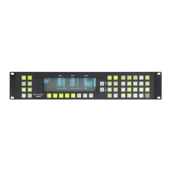
Page 75: Drawings
NV9601 User’s Guide Use continuous scrolling Enabled (checkbox checked). All other options: Disabled (check boxes clear). DHCP The panel is set up to respond to DHCP from the factory. It is possible to assign the panel a fixed IP address using the Panel IP Configuration Utility. Drawings The drawings on the following pages identify features and provide overall and critical dimensions. - Page 76 Technical Details Drawings Fig. 6-1: Front View of the NV9601...
- Page 77 NV9601 User’s Guide Fig. 6-2: Rear and Top Views of the NV9601...
- Page 78 Technical Details Drawings...
-
Page 79: Glossary
Glossary (AES/EBU (Audio Engineering Society/European Broadcasting Union). AES and EBU are standards organizations. Breakaway A condition where a destination has multiple sources on different levels. Category A category represents a set of devices. (The concept of categories exists to make it easier to select devices at a control panel.) A category can contain sources, destinations, or devices that are both sources and destinations. - Page 80 Glossary Source/ The term “source device” is used interchangeably with “source” and the term “destination Destination device” is used interchangeably with “destination. ” A source is a device that is connected to one or more input ports. A destination is a device that is connected to one or more output ports.
-
Page 81: Index
Index level map ......25, 46 lock ......25, 41, 47 menu . - Page 82 Index Cable, Ethernet ......10 Data routing ....... . . 8 Cancel (button) .
- Page 83 NV9601 User’s Guide EBU ......... 69 Head office, contact .
- Page 84 Index Messages acquiring IP address ....10, 60 no server ....... . 11 Last page, Acrobat .
- Page 85 NV9601 User’s Guide NV9000-SE Utilities ... 2, 9–11, 13, 16, 38 Panel/router network ....11, 57 user’s guide .
- Page 86 Index Support, contact ......77 Switching devices ......69 Symbols Salvo (button) .
-
Page 87: Contact Us
Contact Us Grass Valley Technical Support For technical assistance, contact our international support center, at 1-800-547-8949 (US and Canada) or +1 530 478 4148. To obtain a local phone number for the support center nearest you, please consult the Contact Us section of Grass Valley’s website ( www.grassvalley.com An online form for e-mail contact is also available from the website.
Need help?
Do you have a question about the grass valley NV9601 and is the answer not in the manual?
Questions and answers