
Related Manuals for Belden Hirschmann MIPP


Summary of Contents for Belden Hirschmann MIPP
- Page 1 Description and Assembly Instructions Modular Industrial Patch Panel MIPP MIPP Technical Support Release 01 01/12 HAC.Support@Belden.com...
- Page 2 In addition, we refer to the conditions of use specified in the license contract. You can get the latest version of this manual on the Internet at the Belden product site (www.beldensolutions.com). Printed in The Netherlands Belden Wire &...
-
Page 3: Table Of Contents
Contents Legend Device description Description of housing Description of the modules Device installation Unpacking and checking Installing modules 2.2.1 Remove the module from the housing 2.2.2 Installation of installation cables on LC and SC modules 2.2.3 Installation of installation cables on CU modules 2.2.4 Installing the module into the housing Installing the device and grounding 2.3.1 Mounting on the DIN rail... -
Page 4: Safety Instructions
Safety instructions Certified usage The device may only be employed for the purposes described in the catalog and technical description, and only in conjunction with external devices and components recommended or approved by the manufacturer. Environment The device may only be operated at the specified ambient temperatures (temperature of the ambient air at a distance of up to 5 cm from the device) and at the specified humidity. -
Page 5: Legend
Failure to observe this warning can endanger your sight. Maintenance When designing this device, Belden was largely able to forego using wear parts. The parts subject to wear are dimensioned to last longer than the lifetime of the product when it is operated normally. Operate this device according to the specifications (see “Technical... -
Page 6: Device Description
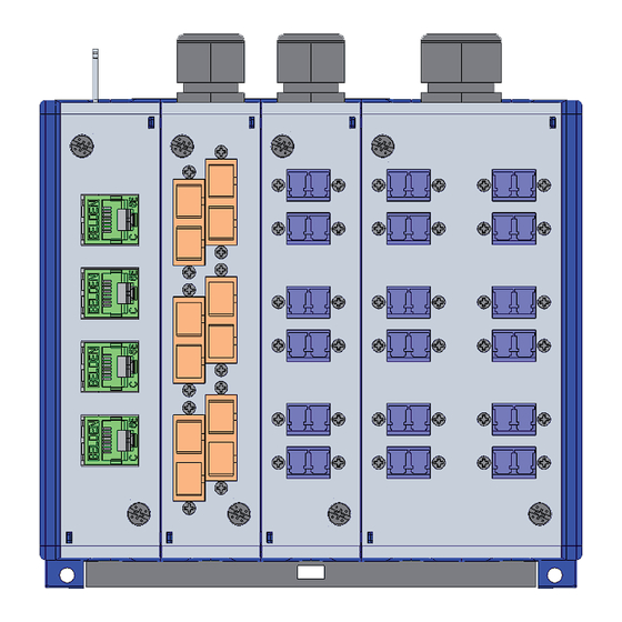
Device description The Modular Industrial Patch Panel (MIPP) is a device for coupling and managing fiber optics and electrical conductors for data exchange. It is designed for the special requirements of industrial automation and production and meets relevant industry standards. The device is suitable for Ethernet component connections according to IEEE 802.3-2000. - Page 7 Figure 1: MIPP with 3 single modules and 1 double module 1 – Cable entry with bracket for tie wraps 2 – Cable entry with cable gland M16 3 – Cable entry with cable gland M16 4 – Cable entry with cable gland M20 5 –...
-
Page 8: Description Of Housing
Description of housing The housing has a modular design and is thus adaptable to the number of modules. There is space for a maximum of 6 single modules. The following components are available: 2 housing walls, 1 left and 1 right ... -
Page 9: Description Of The Modules
Description of the modules The modules form the interface between the laid cable and patch cable. Optical fiber cables are connected via adapters, Ethernet cables via RJ45 Keystone jacks. The following modules are available: LC for connecting LC patch cables ... - Page 10 Figure 3: LC single module and LC double module – Components 1 – Cable gland 2 – Fixing screw 3 – LC Duplex adapters 4 – Fixing screw 5 – Fiber guiding "fingers" 6 – Optical fiber splice holder 7 – Fixing for strain relief Figure 4: LC Duplex adapter 1 –...
- Page 11 1.2.2 SC module The following module designs are available: Single module (30 mm width) with SC Duplex adapters for a maximum of 12 fibers Double module (60 mm width) with SC Duplex adapters for a maximum of 24 fibers The SC module consists of the following components: ...
- Page 12 Figure 6: SC Duplex adapter 1 – Hole for assembly 2 – Connector inlet The following cable types can be used: OF loose tube cable Tight buffered cable Semi-tight buffered cable The following connector types can be used: ...
- Page 13 Figure 7: CU single module – Components 1 – Cable inlet with bracket for tie wraps 2 – Ground screw 3 – Fixing screw 4 – RJ45 Keystone jacks 5 – Fixing screw Figure 8: RJ45 Keystone jack 1 – Latch 2 –...
-
Page 14: Device Installation
Device installation The device has been developed for practical application in a harsh industrial environment. Accordingly, the installation process has been kept simple. The following sequence has proven itself in practice during installation: Unpack delivery and inspect Assemble the modules ... -
Page 15: Remove The Module From The Housing
2.2.1 Remove the module from the housing Proceed as follows: Loosen the 2 screws on the front of the module and pull the module forward out of the housing. Figure 9: Removing the module Note: If you would like to add another module to the device, please refer to chapter “Housing expansion for additional modules”... -
Page 16: Installation Of Installation Cables On Lc And Sc Modules
2.2.2 Installation of installation cables on LC and SC modules Proceed as follows: Loosen the cable gland. Guide the installation cable through the cable gland in the module. Remove the jacket from the installation cable to a sufficient length for termination. -
Page 17: Installing The Module Into The Housing
Figure 10: Cables arrangement – Top view Fix the installation cables to the metal bracket with the Velcro strip included. Fix the ground cable (not included in the delivery) with one end on the ground connection of the module and the other end to the ground bar of the installation system. -
Page 18: Installing The Device And Grounding
Installing the device and grounding 2.3.1 Mounting on the DIN rail You have the option of assembling the device on a 35 mm DIN rail according to DIN EN 60175. No tools are necessary. Proceed as follows: Install the slider into the DIN rail (see fig. - Page 19 Proceed as follows: Remove the wall mounting plate from the device. Position the wall mounting plate as a drill hole guide at the desired spot on the wall and draw-in the four bore holes. Drill 4 holes and insert the 4 wall anchors into the holes. ...
-
Page 20: Expanding The Device
Expanding the device You have the following options to expand the device according to your needs: Add module to device Add RJ45 Keystone jacks to CU modules Assembly of LC, SC and CU modules The device can be expanded until the total of 6 single modules. 1 double module can be used instead of 2 single modules. -
Page 21: Housing Expansion For Additional Modules
3.1.2 Housing expansion for additional modules Proceed as follows: Remove all modules. Remove the 2 bolts at the left housing wall. Remove the right housing wall (see fig. 14). Figure 14: Removing the housing wall Install a spacer that corresponds to the module shape: ... -
Page 22: Technical Data
Technical data General technical data Dimensions Single module, front side 30 mm × 133 mm × 146 mm W × D × H Single module, rear 30 mm × 133 mm × 167 mm Double module, front side 60 mm × 133 mm × 146 mm Double module, rear 60 mm ×... - Page 23 Accessories and order numbers Description Order number Pack of 12 Pigtails of 0.6 m length in 12 different colours LC/UPC SM/OS2 9/125 900 micron CA00551 LC/PC OM1 62,5/125 900 micron CA00552 LC/PC OM2 50/125 900 micron CA00553 LC/PC OM3 50/125 900 micron CA00554 LC/PC OM4 50/125 900 micron CA00555...
- Page 24 Underlying norms and standards Designation IEC 61754-4, -15, -19, -20 Optical connector IEC 60825-1 Laser product safety IEEE 802.3-2009 Information technology UL 1863 Communication Circuit Accessories Table 2: List of based specifications and standards. Certified devices are marked with a certification identifier. Certifications ...
-
Page 25: A Further Support
Further Support Technical Questions and Training Courses In the event of technical queries, please contact your local Belden distributor or Belden office. You can find the addresses of our distributors on the Internet: www.beldensolutions.com. Our support line is also at your disposal: ...
Need help?
Do you have a question about the Hirschmann MIPP and is the answer not in the manual?
Questions and answers