Table of Contents
Advertisement
Quick Links
MFJ-214 Instruction Manual
Linear Amplifier Saver
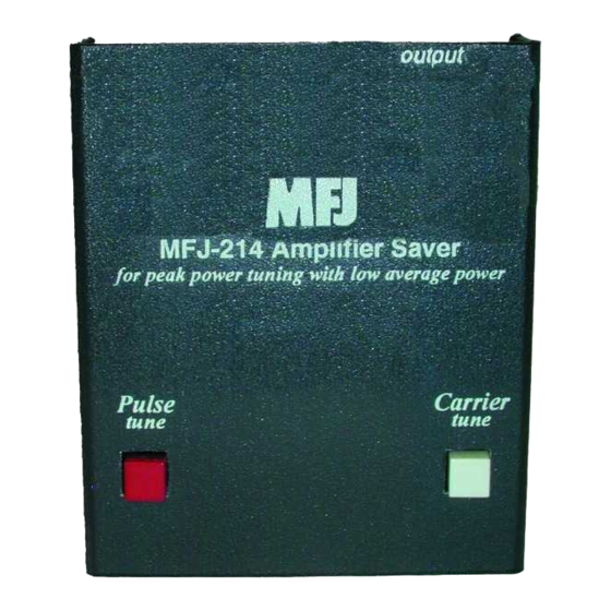
MFJ-214 Linear Amplifier Saver
The MFJ-214 Linear Amplifier Saver relieves temperature related stress on
amplifiers, tuners, and dummy loads while allowing proper system adjustments.
It allows amplifiers to be properly adjusted without the use of long steady
carriers.
The MFJ-214 Linear Amplifier Saver allows tuning of an amplifier with full
required drive from the transceiver without over-heating the finals or anything
else in the RF line. It sends a series of pulses to the transceiver allowing the
peak power to be high enough to drive the amplifier to full power, but with the
average power being low enough not to over-heat the final(s).
The MFJ-214 Linear Amplifier Saver works with any solid state amateur
transceiver or transmitter, and all other equipment using positive keying line
voltages below 50 volts open circuit and 100 mA closed key current. It can also
be used with negative voltage key lines (commonly found in older tube type
radios) provided keying voltages are below 25 volts dc open circuit.
The MFJ-214 Linear Amplifier Saver can also be used as a valuable
troubleshooting and diagnostic aid. The MFJ-214 Linear Amplifier Saver can be
used in performance tests of QSK systems, wattmeters, and other equipment (see
Appendix).
The MFJ-214 Linear Amplifier Saver uses a single 9-volt battery for power, with
battery life dependent on operating and storage time. To install the battery
remove the cover by removing the two screws (one on each side) that secure it.
A battery clip and holder, located on the left side of the enclosure, are provided
for installing the 9-volt battery.
Technical Description
The MFJ-214 Linear Amplifier Saver uses a 555 timer driving an FET open
drain switch. Two internal controls allow independent adjustment of both pulse
repetition rate (PULSE RATE) and on-to-off time duty cycle (DUTY CYCLE).
PULSE RATE is adjustable from about 17 to 40 pulses per second, while DUTY
CYCLE is adjustable from about 10 to 90 percent. The keying time intervals are
typically adjustable from 2- 40 mS "on" time, and a 24 to 60 mS pulse repetition
time interval.
Minimum duty cycle and the slowest PULSE RATE occur at the full
counterclockwise settings of both internal controls. The controls are designed to
accept a small flat blade screwdriver.
1
Advertisement
Table of Contents

Summary of Contents for AMERITRON MFJ-214
- Page 1 QSK systems, wattmeters, and other equipment (see appendix). The MFJ-214 Linear Amplifier Saver uses a single 9-volt battery for power, with battery life dependent on operating and storage time. To install the battery remove the cover by removing the two screws (one on each side) that secure it.
- Page 2 PULSE RATE and DUTY CYCLE The MFJ-214 has two internal controls that adjust Pulse rate and duty cycle. As indicated by the names, these controls adjust the rate at which the transmit keying pulses occur (pulse rate), and the ratio of on- to-off time (duty cycle).
- Page 3 This stretches the pulse duty cycle out, making the actual RF envelope have a longer duty cycle than the actual keying waveform from the MFJ-214. Because of this effect, the MFJ-214 Linear Amplifier Saver may actually produce a 100% duty cycle waveform at high (clockwise) PULSE RATES with longer (clockwise) on-time DUTY CYCLE settings.
- Page 4 (less than 50 volts and 100 mA) and the outer shell grounded. If the case of the MFJ-214 Linear Amplifier Saver is kept isolated from ground, the MFJ-214 Linear Amplifier Saver can be used with negative keying line voltage radios provided radio keying line voltages are below 25 volts.
- Page 5 MFJ-214 Instruction Manual Linear Amplifier Saver mode and depress the pulse tune button on the MFJ-214 Amplifier Saver. Tune the amplifier for peak output power. Note: Due to the response time of most non-peak-reading RF watt meters, the meter will read a low average power, but the amplifier will be tuned for full peak power.
- Page 6 MFJ-214 Instruction Manual Linear Amplifier Saver Schematic...
- Page 7 MFJ-214 Instruction Manual Linear Amplifier Saver Parts List Designator Description R3, R4 Resistor, 1K OHM 100-3100 Resistor, 10K OHM 100-4100 Resistor, 47K OHM 100-4470 R6, R7 Resistor, Trimpot, 500K OHM 133-5500 C1, C3 Capacitor, .01uF 200-0004 C2, C4 Capacitor, .1uF...
- Page 8 The MFJ-214 Linear Amplifier Saver can be used to evaluate QSK systems. In one test configuration, a continuous signal source is loosely coupled to the dummy load. The receiver is tuned to this signal source, and the MFJ-214 Linear Amplifier Saver controls are adjusted until the test signal is clearly audible. The maximum QSK receive speed is found by measuring the PULSE RATE, and multiplying the PULSE RATE by 2.4.


Need help?
Do you have a question about the MFJ-214 and is the answer not in the manual?
Questions and answers