Table of Contents
Advertisement
Quick Links
Advertisement
Table of Contents

Subscribe to Our Youtube Channel
Related Manuals for VideoLogic Proteus-V


Summary of Contents for VideoLogic Proteus-V
- Page 1 PROTEUS- ESSENTIAL User Manual Version V2.15 Oct 29, 2021...
-
Page 2: Table Of Contents
ABLE OF ONTENTS GENERAL OVERVIEW ........................................... 4 TYPICAL INTERCONNECT DIAGRAM ...................................... 5 GLOSSARY TERMS ............................................6 COMMUNICATION ............................................6 ..............................................6 PORTS ..........................................6 PORTS BAUD RATES ..........................................6 PORTS DEVICE TYPES .......................................... 7 PORTS CONFIGURATION COM1 ................................................7 COM2 ................................................7 COM3: USB .......................................... - Page 3 APPS .................................................. 30 ....................................... 30 QUADRATURE OR SIMPLE COUNTERS ..............................................34 NALOG XY M ............................................38 EASUREMENT ................................................40 ETICLE ........................................42 LANE ITUATION WARENESS .......................................... 45 ITUATION WARENESS ................................................48 SLIDERS ................................................. 50 COMPASS .............................................. 51 COUNT UP TIMER PROTEUS COMMANDS ..........................................
-
Page 4: General Overview
ENERAL OVERVIEW Video Overlay is a method by which computer-generated images are superimposed on video. Properly transformed images appear as if they are an integral part of the scene without impeding the video of the actual environment. The primary purpose of PROTEUS is to provide the ability to insert text, logos and GPS data. Numerous apps have been developed to enhance this product. -
Page 5: Typical Interconnect Diagram
YPICAL INTERCONNECT DIAGRAM Diagram below illustrates a few the possible applications. -
Page 6: Glossary Terms
LOSSARY TERMS Term Definition Software Communication Specification Comma Separated Values Terminal Block User Manual OMMUNICATION PORTS PROTEUS provides 3 x serial ports for communication with the external devices: COM PORT Location Pin assignments COM1 RS232: Rear Panel DB9 2=RX, 3=TX, 5=GND COM2 RS232: Internal J54 &... -
Page 7: Com Ports : Configuration
PORTS CONFIGURATION Press F9 to display the Main Menu. Follow to configure COM ports for desire baud rate & device. Figure 1-Figure 2 Figure 1 Figure 2 COM1 COM1 (DB9) is configured as DTE (PC) i.e., RX=Pin2, TX=Pin3. Thus, sensors such as GPS can be directly connected to the DB9 without the need for NULL modem cable. -
Page 8: Csv Formats
FORMATS A CSV is an ASCII sentence composed of a unique header, followed by up to 12 comma separated values and a checksum. $Header,VAL1,VAL2,VAL3,VAL4,VAL5,VAL6,VAL7,VAL8,VAL9,VAL10,VAL11,VAL12*CS Signifies start of the sentence. Header Sentence header. Follow Figure 1-2 to define your unique sentence header. VALn Each sentence contains multiple values (VALn) delimited by commas. -
Page 9: Ethernet Port
THERNET PORT This port can be used to receive remote commands defined in SCS (Software Communication Specification) or any other CSV1 type data formats. • 10M/100M auto sensing network interface • Networking: Static or DHCP IPv4 addressing • Subnet Mask: Configurable. Default 255.255.255.0 •... - Page 10 Free utility can be used to send commands to Proteus. Follow to configure Packet Sender only once. Packet Sender Figure 7 Figure 7 Follow to send commands to Proteus. For example, use any text editor i.e., and open file “0-TestCommands.txt” located Figure 8 - Figure 9 Notepad++ in the Script folder.
-
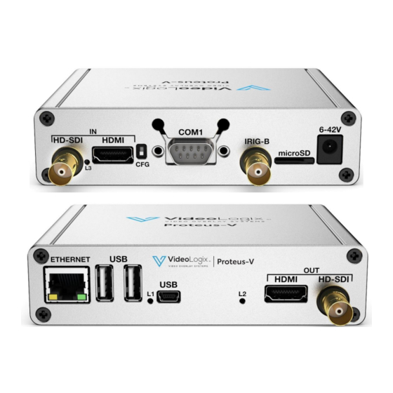
Page 11: Video Input & Output
& IDEO INPUT OUTPUT PROTEUS provides the following video input & output: • SDI (HD & SD) • HDMI (HD & SD) PROTEUS does not support HDMI video with HDCP. It can only process one video input at a given time. If more than one input is connected at the same time, PROTEUS selects a video input based on the following priorities: 1. -
Page 12: Video Frame Rates
IDEO FRAME RATES PROTEUS is compatible with the following video formats: 1080i @ 50 / 60 Hz 1080p @ 23.98 / 24 / 25/ 29.97/ 30 Hz 1080PsF @ 23.98 / 24 Hz 720p @ 50 / 59.94 / 60 Hz NTSC 480i @ 60 Hz PAL 576i @... -
Page 13: Composite Input (Pip)
(PIP) OMPOSITE NPUT IRIG input can also be used to input a composite video NTSC (M, J, 4.43) or PAL (B,D,G,H,I,M,N,CN) for purpose of superimposing it on a HD video. To enable PIP follow the pictures below. Composite video (as shown below as colorbar) can be superimposed anywhere on the 1920 x 1080. -
Page 14: Load Configuration
ONFIGURATION PROTEUS supports up to 16 configuration files. When loading a configuration file i.e., , Proteus copies the file into ll subsequent ROV.bin Config.bin. changes will be stored into the original Config.bin ROV.bin In order to avoid losing your modified configuration by accidental overwrite, highlight and press to save into... -
Page 15: Text, Logo And Data Inserter
LOGO AND DATA INSERTER UICK UTORIAL ISPLAY TIME DATE 1. Press F9 to display main menu 2. Follow Figure 11 - Figure 13 to insert the desired parameter 3. On Figure ↕ arrow keys to select “RTC Time” 13, use 4. -
Page 16: Display Text Via Keyboard
ISPLAY TEXT VIA KEYBOARD Press F9 to display Main Menu. Follow Figure 14 - Figure 15 to type-in or edit pre-exiting texts. Figure 14 Figure 15 Follow Figure 16 - Figure 17 to display text on video. Figure 16 Figure 17 ↲... -
Page 18: Display Images Via Keyboard
ISPLAY MAGES VIA KEYBOARD Please review your image on how to prepare images for use with PROTEUS. Appendix D – display Press F9 to display Main Menu. Follow Figure 18 - Figure 19 to display images. Figure 18 Figure 19 ↲... -
Page 19: Display Gps Data
ISPLAY GPS DATA Two independent GPS modems can be connected to COM1 & COM2 at the same time. • • COM ports are fixed for N, 8, 1. Follow Figure 1 - Figure 2 to configure for desire baud rate $GPRMC, $GPGGA, $PTSAG, $GPWPL, $GPGSA, $GPGSV, $GPGGL…. - Page 20 To customize the sample file to meet your needs, follow Figure 20 - Figure 22. Figure 20 Figure 21 Figure 22 ↲ While in to select desire GPS parameter. Press to select “On”. Use shortcuts keys to format the text as described below: ↕...
-
Page 21: Display Nmea 0183 Data
0183 ISPLAY NMEA DATA • PROTEUS intrinsically supports many NMEA sentences such as $GPRMC, $GPGGA, $PTSAG, $GPWPL, $GPGSA, $GPGSV, $GPGGL, $SDDPT, $SDDBT, $WIMTW, $WIMWV, $VNINS, $VNIMU, $VNYPR, $PTNTHPR, $HCHDG, $HCHDT, $HCC, $DBS, $PCIT, $PCIPR, etc. • For above messages, just configure COM port and PROTEUS is ready to receive messages &... -
Page 22: Display Text Via Rs232
RS232 ISPLAY TEXT VIA ISPLAY VALUES FROM CSV SENTENCE A CSV (Comma Separated Values) is an ASCII sentence composed of a unique header, followed by up to 12 comma separated values and a checksum. $Header,VAL1,VAL2,VAL3,VAL4,VAL5,VAL6,VAL7,VAL8,VAL9,VAL10,VAL11,VAL12*XX • NMEA-0183 messages are CSV sentences •... - Page 23 sample CSV file is provided with your PROTEUS. To load it, press F9, go to “Config: Load” and select “CSV”. Sentence-A values VAL1..VAL8 Sentence-B values VAL1..VAL4 Sentence-C values VAL1..VAL4 Sentence-D values VAL1..VAL4 Misc. Parameters Texts, RTC Time & Date, Logo. Fully configurable by the user...
- Page 24 Upon transmission of the following sentences (use PuTTY @115K, N,8 ,1), their values should appear as shown in Figure 26. $SentenceA,1,22,333,4444,55555,666666,7777777,88888888*XX $SentenceB,A,BB,CCC,DDDD*XX $SentenceC,Pitch,Roll,Yaw,Heading*XX $SentenceD,This,is,an,Example*XX Figure 26 Any individual value can also be updated by sending command $VL43. For example: • To change VAL7 of SentenceA to send: $VL43,46,777*XX.
- Page 25 To customize the sample file to meet your needs, follow Figure 27-Figure 32. Figure 27 Figure 28 Figure 29 Figure 30 Figure 31 Figure 32 ↲ While in Figure 29- Figure 32 to select desire CSV value. Press to select “On”. Use shortcuts keys to format the text as described below: ↕...
-
Page 26: Display Nmea 2000 Data
2000 ISPLAY NMEA DATA Follow to enable CAN communication by setting “COM2 mode” to CAN. Figure 1 Figure 2 Sensor signals “CAN-H” and “CAN-L” must be connected to the internal terminal block J48 as shown in PCB specification. Follow to display NMEA2000 messages. Figure 33 Figure Figure 35... -
Page 27: Display Tilt Sensor
ISPLAY TILT SENSOR Proteus has a built-in 3D accelerometer. Follow and to display the sensor data: Figure 36 - Figure 38 Figure 36 Figure 37 Figure 38... -
Page 28: Real Time Annotation
EAL TIME ANNOTATION Follow to enable “Real time annotation”. Figure 39 Figure 40 The default settings for annotation is: • Upper left corner (x, y) is 100, 100 • Font size #2 • Text color yellow • Text background color blue To change the default setting, visit and follow through... -
Page 29: Append Millisecond Counter To Irig , Gps , Rtc Time
PPEND MILLISECOND COUNTER TO IRIG RTC TIME Follow Figure 39 - Figure 40 to append millisecond count to RTC, IRIB and GPS time. Millisecond counter is reset on second rollover. Once enable, the displayed time will refresh at video frame rate i.e. 30 time per second for 1080p@30 Figure 39 Figure 40... -
Page 30: Apps
QUADRATURE OR SIMPLE COUNTERS • Two Quadrature counters. Counters are 26-bits wide. Maximum count 67,108,863 or ±33,554,431 • Configurable line resolution ��1, ��2, ��4. See diagram below for additional detail • • Dedicated RESET pins Raw counter value can be converted to any unit (distance, speed, etc.) using •... - Page 31 Typical wiring connection for Quadrature Counters Quadrature Counter 1 Quadrature Counter 2 Electrical Interface Input compatibilty: • 0-5V logic (10ma sink current) • Frequency < 10MHz RESET1 RESET2 Power & ground can be provided to the quadrature encoder via J55: Typical wiring connection for Simple Counters Simple Counter 1 Simple Counter 2...
- Page 32 ONFIGURE OUNTERS sample Quadrature file is provided with your PROTEUS. To load it, press F9, go to “Config: Load” and select “Quadrature”. Raw count ������_���������� = 67,108,863 or ± 33,554,431 Mapped count ������������_���������� = �� ∗ ������_���������� + �� Misc. Parameters Title, Time &...
- Page 33 To customize the sample file to meet your needs, follow Figure 41 Figure 43 Figure 41 Figure 42 Figure 43 Follow Figure 44 - Figure 45 to display map and raw counts. Figure 44 Figure 45 XAMPLE Configure counter 1 for 0.0023 inch/count and display result. •...
-
Page 34: Analog Data
NALOG Four Analog inputs • Input range 0..3.3V • • Internal low pass RC filter (24Ω, 5600pF) • 12-Bit ADC. Analog signals are at 1KHz. Each ADC is average of 4 consecutive (2µs apart) samples Sampled Sample • is average of 1 to 64 (user selectable) most recent Samples displays the most recent sample and displays average of the most recent 8 samples... - Page 35 sample Analog file is provided with your PROTEUS. To load it, press F9, go to “Config: Load” and select “Analog”. Raw Analog values = 0. .4095 Mapped Analog values = �� ∗ + �� mapped Misc. Parameters Title, Time & Date, Logo. Fully configurable by the user...
- Page 36 To customize the sample file to meet your needs, follow Figure 46 Figure 48 Figure 46 Figure 47 Figure 48 Follow to display map and raw values. Figure 49 - Figure 50 Figure 49 Figure 50...
- Page 37 XAMPLE Configure analog channel 1 to convert 0-3.3V input to display 0 - 667.5 feet. Input Represent ADC Count (feet) 3.3V 4095 667.5 Length Slope = 0.163 y = 0.163x + 0.0272 Intercept = 0.0272 1000 2000 3000 4000 Follow to set CH1 “Slope”...
-
Page 38: Xy Measurement
XY M EASUREMENT sample XY measurement file is provided with your PROTEUS. To load it, press F9, go to “Config: Load” and select file “XY Measurement” Markers ��1, ��2, ��1, ��2 markers. Can be moved via Analog inputs, quadrature inputs, RS232 command, arrow keys Delta X DX = |x2 –... - Page 39 To customize the sample file to meet your needs, follow Figure 51 Figure 53 Figure 51 Figure 52 Figure 53 There are 4 options for X1, X2, Y1, Y2 marker movement: Apply 0-3.3V to CH1-CH4 Analog Inputs Connect incremental encoder switches to quadrature inputs# 1,2. Quadrature Inputs (Toggle to select between horizontal &...
-
Page 40: Reticle
ETICLE sample Reticle file is provided with your PROTEUS. To load it, press F9, go to “Config: Load” and select “Reticle”. Reticle position Reticle X&Y position. Center is at 0,0 Reticle can be a PNG image, adjustable crosshair or square box. See a few examples below. If an image is selected, it must reside on the microSD card. - Page 41 PNG Images Adjustable square, crosshair To customize the sample file to meet your needs, follow Figure 54 Figure 56 Figure 54 Figure 55 Figure 56 There are 4 options for Reticle movement: Apply 0..3.3V to CH1-CH2 Analog Inputs Connect two incremental encoder switches to quadrature inputs# 1,2 Quadrature Inputs Send command to set registers...
-
Page 42: Plane Situation Awareness
LANE ITUATION WARENESS sample Plane file is provided with your PROTEUS. To load it, press F9, go to “Config: Load” and select “Plane”. GPS data Read from GPS attach to COM1 or COM2 Plane Situation Widget Please see below for detail description Compass Rolling compass widget 4A, 4B, 4C... - Page 43 LANE ITUATION WARENESS IDGET Figure 57, Plane situation awareness widget depicts parameters such as heading, bearing (relative or magnetic), roll, pitch, azimuth, As shown in elevation. The size of the widget is governed by the background image shown in . Larger image will result in a larger widget. Figure 58 Background image resides on the microSD and can be replaced by a user-provided image for different size and look &...
- Page 44 Figure 60 Follow to specify what register are associated with each parameter. For example, table below shows available options for heading: Register # associated with Heading Description Heading is provided by attaching Garmin GPS modem to COM1 port Heading is provided by attaching Vector NAV INS sensor to any COM port Heading is provided by transmitting a CSV sentence A to any COM port.
-
Page 45: Rov Situation Awareness
ITUATION WARENESS sample ROV file is provided with your PROTEUS. To load it, press F9, go to “Config: Load” and select “ROV”. GPS date Read from GPS attach to COM1 ROV Situation Widget Please see below for detail description Compass Rolling compass widget 4A, 4B, 4C Sliders... - Page 46 ITUATION WARENESS IDGET Figure 62, ROV situation awareness widget depicts parameters such as heading, bearing (relative or magnetic), range to target, roll As shown in and pitch. The size of the ROV widget is governed by the background image shown in .
- Page 47 Figure 65 Follow to specify what register is associated with each parameter. For example, table below shows available options for heading: Register # associated with Heading Description Heading is provided by attaching Garmin GPS modem to COM1 port Heading is provided by attaching Vector NAV INS sensor to any COM port Heading is provided by transmitting a CSV sentence A to any COM port.
-
Page 48: Sliders
SLIDERS Figure 66- Figure 68 PROTEUS provides 4 fully configurable sliders. Follow to configure the sliders. Figure 66 Figure 67 Figure 68 Slider must be linked to a register. Registers are updated via associated sensors or through RS232 commands. When the linked register receives a new value, associated slider is automatically updated. - Page 49 Figure 69...
-
Page 50: Compass
Figure 71 Compass data is provided via “link to register”. For example, if VAL1 of CSV Sentence-A contains heading, use 40. Appendix-A of the Proteus-V SCS.pdf provides register values of all CSV sentences. Rolling compass provides 4 visible spans (30⁰, 45⁰, 60⁰, 90⁰) with 4 different legends described below: •... -
Page 51: Count Up Timer
COUNT UP TIMER Figure 73-Figure 74 PROTEUS provides Count Up timer. Follow to configure the timer. Figure 73 Figure 74 LOCK SOURCE Source Description Internal 27MHz Source for 1msec pre-scaler XTERNAL ONTROLS Description 0 = Pause Timer, 1 = Resume Timer 0 = Reset Timer. -
Page 52: Proteus Commands
PROTEUS COMMANDS Aside from supporting various connected devices, PROTEUS provides over 30 powerful commands to overlay crisp and clear texts, graphics and telemetry generated information into an incoming HD & SD video in real time. Refer to the Software Communication Spec (SCS) for the detail description of each command. -
Page 53: Proteus Registers
Read Register and Write Register commands (refer to SCS for detail). The table in Appendix A of the “Proteus-V SCS.pdf” provides a quick reference for all the registers and their associated properties. The device specific (Cineflex, IMU, GPS ...) registers are automatically updated when the associated device is connected to PROTEUS. -
Page 54: Specifications
PECIFICATIONS AXIMUM INPUT VOLTAGE Min (DCIN) Max (DCIN) Power 6VDC 42VDC 4 watts NPUT CONNECTOR DC power jack is standard 2 conductors, center pin positive, 2.1mm ID, 5.5mm OD. NVIRONMENTAL Specifications Temperature Humidity 0° C to 65° C Operating 10 to 90% RH Non-Condensing Storage Temperature -10°... -
Page 55: Pcb Specification
SPECIFICATION... - Page 56 SDI out 2 x Quadrature Inputs 2 x USB 1 x USB HOST Ethernet HDMI out DEVICE 4 x Analog Inputs 5V, 3.3V HDMI in microSD Power COM2 COM1 SDI in Composite in IRIG in...
-
Page 57: Enclosure Dimension
NCLOSURE DIMENSION... -
Page 58: Appendix A - Keyboard Commands
– PPENDIX A KEYBOARD COMMANDS EYBOARD COMMANDS Keyboard command Description Shortcut to “Edit: User Texts” Launch Main-Menu Save changes & exit Sub-Menu Abort changes and exit Sub-Menu Select an item from the picklist i.e. COM1, COM2… Enter Ctrl + Enter Alt + G Draw 60 x 60 pixel gridlines on video Alt + H... -
Page 59: Appendix B - Updating Firmware
B – U PPENDIX PDATING FIRMWARE This section assumes you have already installed ‘Renesas Flash Programmer’ described in Appendix C. 1. Toggle CFG switch in the rear panel to the lower position 2. Cycle power to PROTEUS 3. Connect mini USB cable from your PC to PROTEUS 4. - Page 60 6. Follow instruction below to load the firmware into Proteus. 7. After ‘Operation completed’, Toggle CFG switch in the rear panel to the upper position 8. Cycle power to PROTEUS and you are done.
-
Page 61: Appendixc - Install Renesas Flash Programmer
C – I PPENDIX NSTALL ENESAS LASH ROGRAMMER MicroSD FOLDERS – DOWNLOAD Copy the content of the microSD card into a PC folder i.e. C:\Videologix-V. Alternatively, download it from unzip it into a folder i.e. C:\Videologix-V. Go to folder C:\Videologix-v\Utilities and launch program ‘Renesas_Flash_Programmer_Package_V30501’. -
Page 62: Appendix D - Display Your Image
D – PPENDIX DISPLAY YOUR IMAGE PNG image must be converted to 32-bit BMP using Pixelformer utility. This utility will preserve pixel level alpha blending. This program is in utility folder on microSD card. Use File-import to open PNG file and File-export to create the BMP file. When prompted, select A8:R8:G8:B8 as shown below. -
Page 63: Appendixe - Create Custom Fonts
E – PPENDIX CREATE CUSTOM FONTS FONT0 through FONT7 can be customized by the user. To create your own fonts, follow steps below: 1. Start PROTEUSApp. This app is in utility folder on microSD card. 2. Go to Font + Bitmask tab. -
Page 64: Appendixf - Terminal Blocks
F – T PPENDIX ERMINAL BLOCKS Care must be taken when inserting wire into terminal blocks. Do not insert thick screwdriver into terminal block as it will permanently damage the internal spring-loaded contacts. In general, any blade with cross section is appropriate. Digikey P#1205202 is factory approved. 0.4mm x 2mm We have learned that X-ACTO Knife shown below works best. -
Page 65: Appendix H - Format Microsd
H – F PPENDIX ORMAT MICRO Disable power before removing or inserting microSD card. • The following instructions only apply to firmware version V2.24 or higher. • microSD card capacity is limited to 2GB, 4GB, 8GB, 16GB, 32GB. • Follow the diagram below to format your microSD card. Select FAT32 as File System and Allocation unit size of 8192...
Need help?
Do you have a question about the Proteus-V and is the answer not in the manual?
Questions and answers