Table of Contents
Advertisement
Quick Links
Advertisement
Table of Contents

Subscribe to Our Youtube Channel
Related Manuals for Siemens SIMOTICS M-1PH1


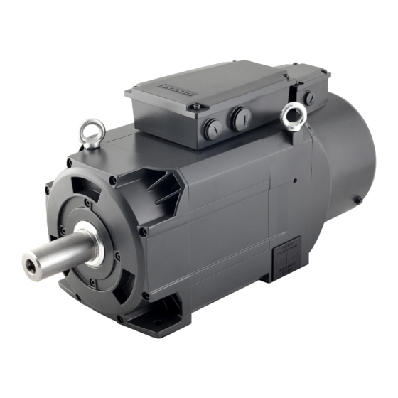
Summary of Contents for Siemens SIMOTICS M-1PH1
- Page 3 1PH1 main motors Introduction Fundamental safety instructions SIMOTICS Motor description Mechanical properties SIMOTICS M-1PH1 1PH1 main motors Preparation for use Mounting the motor Equipment Manual Electrical connection Configuration Commissioning Operation Maintenance Decommissioning and disposal Technical data and characteristics Appendix 09/2021...
- Page 4 Note the following: WARNING Siemens products may only be used for the applications described in the catalog and in the relevant technical documentation. If products and components from other manufacturers are used, these must be recommended or approved by Siemens. Proper transport, storage, installation, assembly, commissioning, operation and maintenance are required to ensure that the products operate safely and without any problems.
-
Page 5: Introduction
Introduction Standard version This documentation only describes the functionality of the standard version. The machine OEM documents any extensions or changes to the motor made by it. For reasons of clarity, this documentation cannot contain all of the detailed information on all of the product types. - Page 6 Internet address for products Products (http://www.siemens.com/motioncontrol) Training The following link provides information on SITRAIN - training from Siemens for products, systems and automation engineering solutions: SITRAIN (http://siemens.com/sitrain) mySupport Extensive assistance and more information can be found under the following link: My Support Links and Tools (https://support.industry.siemens.com/My/ww/en/documentation)
- Page 7 If you have any technical questions, contact Technical Support (https://support.industry.siemens.com). To make a support request, proceed as follows: Precondition You have registered for and logged on to "Siemens Industry Online Support", abbreviated "SIOS". SIOS (https://support.industry.siemens.com/cs/ww/en/) Procedure 1. Click on "Your direct way to the Support Request" or follow the link Support Request (https://support.industry.siemens.com/cs/ww/en/my)
- Page 8 Introduction 1PH1 main motors Equipment Manual, 09/2021, A5E51077676A-AA...
-
Page 9: Table Of Contents
Table of contents Introduction ............................3 Fundamental safety instructions ......................11 General safety instructions ....................11 Equipment damage due to electric fields or electrostatic discharge ........15 Security information ......................16 Residual risks of power drive systems ................. 17 Motor description ..........................19 Highlights and benefits ...................... - Page 10 Table of contents Preparation for use ..........................49 Shipment and packaging ....................49 Transportation and storage ....................49 4.2.1 Transporting ........................50 4.2.2 Storing ..........................52 Mounting the motor ..........................55 Overview ........................... 55 Mounting orientation and outline dimensions ..............56 5.2.1 Mounting orientation ......................
- Page 11 Decommissioning and disposal ......................107 11.1 Decommissioning ......................107 11.2 Disposal ........................... 108 Technical data and characteristics ....................109 12.1 SIMOTICS M-1PH1 main motors ..................109 12.1.1 General technical data ..................... 109 12.1.2 Specific technical data ..................... 110 12.1.2.1 Shaft height 100 ......................110 12.1.2.2...
- Page 12 Table of contents 1PH1 main motors Equipment Manual, 09/2021, A5E51077676A-AA...
-
Page 13: Fundamental Safety Instructions
Fundamental safety instructions General safety instructions WARNING Electric shock and danger to life due to other energy sources Touching live components can result in death or severe injury. • Only work on electrical devices when you are qualified for this job. •... - Page 14 Fundamental safety instructions 1.1 General safety instructions WARNING Electric shock due to damaged motors or devices Improper handling of motors or devices can damage them. Hazardous voltages can be present at the enclosure or at exposed components on damaged motors or devices. •...
- Page 15 • Therefore, if you move closer than 20 cm to the components, be sure to switch off radio devices or mobile telephones. • Use the "SIEMENS Industry Online Support app" only on equipment that has already been switched off. WARNING Unrecognized dangers due to missing or illegible warning labels Dangers might not be recognized if warning labels are missing or illegible.
- Page 16 Fundamental safety instructions 1.1 General safety instructions Note Important safety notices for Safety Integrated functions If you want to use Safety Integrated functions, you must observe the safety notices in the Safety Integrated manuals. WARNING Active implant malfunctions due to electromagnetic fields Electromagnetic fields (EMF) are generated by the operation of electrical power equipment, such as transformers, converters, or motors.
-
Page 17: Equipment Damage Due To Electric Fields Or Electrostatic Discharge
Fundamental safety instructions 1.2 Equipment damage due to electric fields or electrostatic discharge WARNING Fire due to incorrect operation of the motor When incorrectly operated and in the case of a fault, the motor can overheat resulting in fire and smoke. This can result in severe injury or death. Further, excessively high temperatures destroy motor components and result in increased failures as well as shorter service lives of motors. -
Page 18: Security Information
Siemens’ products and solutions undergo continuous development to make them more secure. Siemens strongly recommends that product updates are applied as soon as they are available and that the latest product versions are used. Use of product versions that are no longer supported, and failure to apply the latest updates may increase customer’s exposure to... -
Page 19: Residual Risks Of Power Drive Systems
Fundamental safety instructions 1.4 Residual risks of power drive systems Residual risks of power drive systems When assessing the machine- or system-related risk in accordance with the respective local regulations (e.g., EC Machinery Directive), the machine manufacturer or system installer must take into account the following residual risks emanating from the control and drive components of a drive system: 1. - Page 20 Fundamental safety instructions 1.4 Residual risks of power drive systems 1PH1 main motors Equipment Manual, 09/2021, A5E51077676A-AA...
-
Page 21: Motor Description
Highlights and benefits Overview The SIMOTICS M-1PH1 main motors, referred to as 1PH1 motors in the following, are used for the machine tool business with the SINUMERIK 808D ADVANCED control system coupled with the high performance SINAMICS V70 spindle drives or the SIMATIC control system coupled with the SINAMICS G120 converters. -
Page 22: Use For The Intended Purpose
When necessary, take into account deviations regarding approvals or country-specific regulations. • If you have any questions regarding the intended use, please contact your local Siemens office. • If you wish to use special versions and design variants whose specifications vary from the motors described in this document, then first contact your local Siemens office. -
Page 23: Scope Of Delivery
Motor description 2.3 Scope of delivery Scope of delivery 2.3.1 Motor package Component Illustration Shaft Rated Rated Article number height power speed (mm) (kW) (r/min) SIMOTICS M- 1000 1PH1103-1☐D1☐-☐GA0 1PH1 main 1500 1PH1101-1☐F1☐-☐GA0 motors 1000 1PH1105-1☐D1☐-☐GA0 1500 1PH1103-1☐F1☐-☐GA0 1500 1PH1105-1☐F1☐-☐GA0 1000 1PH1131-1☐D1☐-☐GA0 1000... - Page 24 Motor description 2.3 Scope of delivery Article number explanation (example) 1PH1 main motors Equipment Manual, 09/2021, A5E51077676A-AA...
-
Page 25: Cables And Connectors
Motor description 2.3 Scope of delivery 2.3.3 Cables and connectors Cables SINAMICS V70 spindle drive to 1PH1 motor Component Illustration Article number Length (m) MOTION-CONNECT 500 power cable 6FX5008-1BB21-1DA0 (4 × 2.5 mm , raw cable), for 1PH1 3.7 kW motor MOTION-CONNECT 500 power cable 6FX5008-1BB31-1DA0 (4 ×... - Page 26 Motor description 2.3 Scope of delivery Recommended connectors for 1PH1 motor power cables Power cable Motor side Drive side Cross-section Supplier Article Picture Quantity Used for Sup- Article Picture Quantity Used for number (pieces) plier number (pieces) 4 × 2.5 mm RNYL 2-5 U/V/W SNYL2-4...
-
Page 27: Device Combination
2.3 Scope of delivery 2.3.4 Device combination The table below lists the 1PH1 motors and configurable V70 spindle drives. You can select the desired spindle drive according to the motor: SIMOTICS M-1PH1 motors Power cable SINAMICS V70 spindle drive (cross-section, Rated... -
Page 28: Derating Factors
NOTICE Damage to the motors For surrounding air temperatures > 55 °C, please contact your local Siemens office. The standard motors are not suitable for use in corrosive atmospheres, atmospheres with a high salt content, or in outdoor applications; otherwise, the motors may be damaged. -
Page 29: Mechanical Properties
Mechanical properties Directives and standards Standards that are complied with The 1PH1 motors comply with the following standards: • IEC/EN 60034-1: Rotating electrical machines – Dimensioning and operating behavior • IEC/EN 60204-1: Safety of machinery – Electrical equipment of machines; general requirements •... -
Page 30: Cooling
The 1PH1 motors comply with the requirements of the customs union Russia/Belarus/Kazakhstan (EAC). Quality systems Siemens AG employs a quality management system that meets the requirements of ISO 9001 and ISO 14001. Certificates for the 1PH1 motors can be downloaded from the Internet at the following link: Certificates for the 1PH1 motors (https://support.industry.siemens.com/cs/products?search=1PH1&dtp=Certificate&mfn=ps&o... - Page 31 0.71 Note Higher ambient temperatures For ambient temperatures > 50 °C, contact your local Siemens office. The 1PH1 motors are not suitable for use in corrosive atmospheres or atmospheres with a high salt content, or in outdoor applications. Minimum clearance between a fan and parts/components mounted by the customer...
-
Page 32: Degree Of Protection
Mechanical properties 3.3 Degree of protection Degree of protection Designation of the degree of protection The degree of protection in accordance with EN 60034-6 (IEC 60034-6) is described with letters "IP" and two digits (for example, IP54). IP = International Protection 1st code number = protection against ingress of foreign bodies 2nd code number = protection against harmful ingress of water When motors are assigned to a specific degree of protection, a standardized, brief test... -
Page 33: Construction Types
Mechanical properties 3.4 Construction types Construction types Mounting orientation The SIMOTICS M-1PH1 main motor supports flange mounting and foot mounting as shown below: Mounting method Standard type of construction Rotated type of construction Foot mounting IM B3 IM V5 Flange mounting... -
Page 34: Motor Dimensions
Mechanical properties 3.5 Motor dimensions Motor dimensions Motor dimensions Shaft height 100 mm: flange mounting (unit: mm) 1PH1 main motors Equipment Manual, 09/2021, A5E51077676A-AA... - Page 35 Mechanical properties 3.5 Motor dimensions Shaft height 100 mm: foot mounting (unit: mm) 1PH1 main motors Equipment Manual, 09/2021, A5E51077676A-AA...
- Page 36 Mechanical properties 3.5 Motor dimensions Shaft height 132 mm: flange mounting (unit: mm) 1PH1 main motors Equipment Manual, 09/2021, A5E51077676A-AA...
- Page 37 Mechanical properties 3.5 Motor dimensions Shaft height 132 mm: foot mounting (unit: mm) 1PH1 main motors Equipment Manual, 09/2021, A5E51077676A-AA...
-
Page 38: Bearing
Mechanical properties 3.6 Bearing Bearing 3.6.1 Bearing types and bearing versions The 1PH1 motors support only the deep-groove ball bearing, which is suitable for the following applications: • Coupling output • Planetary gearboxes, low radial forces See the following table for the bearing lifetime based on the bearing versions at the average operating speed: Shaft Bearing version... -
Page 39: Shaft Extension
The force diagrams apply to standard shaft extensions at the DE. For smaller shaft diameters, only reduced radial forces or none at all may be transmitted. For force levels going beyond the upper and lower limits, contact your local Siemens office. NOTICE... - Page 40 Mechanical properties 3.8 Radial and axial forces NOTICE Mechanical destruction of the motor If the motor supports higher forces when force/torque boosting elements are used, the flange or feet of the motor can be torn off. • Make sure that the force/torque boosting elements, for example, gearboxes or brakes, absorb the higher forces.
-
Page 41: Axial Force
Mechanical properties 3.8 Radial and axial forces 3.8.2 Axial force The axial force acting on the locating bearings comprises the following components: • Axial force in operation Axial forces acting externally on the motor, for example, gearboxes with helical gearing and machining forces through the tool •... -
Page 42: Radial And Axial Force Diagrams
Mechanical properties 3.8 Radial and axial forces 3.8.3 Radial and axial force diagrams Permissible radial forces Shaft height 100 Shaft height 132 1PH1 main motors Equipment Manual, 09/2021, A5E51077676A-AA... - Page 43 Mechanical properties 3.8 Radial and axial forces Permissible axial forces Shaft height 100 Shaft height 132, performance bearing version, 12000 h bearing lifetime 1PH1 main motors Equipment Manual, 09/2021, A5E51077676A-AA...
-
Page 44: Radial Eccentricity, Concentricity And Axial Eccentricity
Mechanical properties 3.9 Radial eccentricity, concentricity and axial eccentricity Radial eccentricity, concentricity and axial eccentricity The shaft and flange accuracies are always obtained in accordance with IEC 60072 and DIN 42955-1981 and defined as follows: • Radial eccentricity tolerance: tolerance of the motor shaft (cylindrical shaft extension) in relation to the frame axis •... -
Page 45: Balancing
Mechanical properties 3.10 Balancing 3.10 Balancing Requirements on the process of balancing mounted components - especially belt pulleys In addition to the balance quality of the motor, the vibration quality of the motor with mounted belt pulleys and coupling is essentially determined by the balance quality of the mounted components. -
Page 46: Vibration Response
Mechanical properties 3.11 Vibration response 3.11 Vibration response 3.11.1 Mounting and mounting instructions To ensure smooth, vibration-free motor operation, you must mount the motor correctly and precisely by observing the mounting instructions carefully. For more information, see Section "Mounting the motor (Page 57)". 3.11.2 Natural frequency for mounting The motor is a system that can vibrate at its natural frequency. -
Page 47: Misalignment
Mechanical properties 3.11 Vibration response 3.11.3 Misalignment To avoid or minimize misalignment, you are recommended to use a compensating coupling, as shown in the following figure: You are recommended not to couple the motor directly or rigidly to an output transmission shaft that has its own bearings. -
Page 48: Vibration Stressing
Mechanical properties 3.11 Vibration response Alignment accuracy Proceed through the following steps to align the motor: 1. Align the motor with coupling outputs in such a manner that the center lines of the shafts are parallel with no offset. This ensures that no additional force affects the bearings of the shafts during operation. - Page 49 Mechanical properties 3.11 Vibration response See the following table for maximum permissible radial vibration values Vibration frequency Vibration values < 6.3 Hz Vibration amplitude s ≤ 0.16 mm 6.3 Hz to 250 Hz Vibration velocity v ≤ 4.5 mm/s > 250 Hz Vibration acceleration a radial ≤...
-
Page 50: Vibration Severity
Mechanical properties 3.12 Vibration severity 3.12 Vibration severity The 1PH1 motors are provided with the following vibration qualities in accordance with Siemens/EN 60034-14 (IEC 60034-14): • 1PH11☐☐-1☐F: B (up to 1800 r/min) S (1800 r/min to 10000 r/min) • 1PH11☐☐-1☐D:... -
Page 51: Preparation For Use
Checking the delivery for completeness Upon receipt of the delivery, check immediately whether the components delivered are in accordance with the accompanying documents. Siemens will not accept any claims relating to components missing from delivery and which are submitted at a later date. -
Page 52: Transporting
Preparation for use 4.2 Transportation and storage WARNING Danger to life as a result of incorrect transport and/or lifting of the motor Incorrectly transporting and/or lifting the motor can lead to severe injuries and/or material damage. For instance, the motor can fall. •... - Page 53 Preparation for use 4.2 Transportation and storage Lifting and transporting the motor with a crossbeam (example) Location of the lifting eyebolts on the motor ① Horizontal shaft extension (standard) ② Shaft extension pointing downwards Transporting a motor that has already been operated If you want to transport a motor that has already been operated, proceed as follows: 1.
-
Page 54: Storing
– No harmful gases in the air of the storage area • Protect the motor against shocks and humidity. • Make sure that the motor is covered properly. • Avoid contact corrosion. Siemens recommends you to rotate the shaft extension manually every three months. 1PH1 main motors... - Page 55 Preparation for use 4.2 Transportation and storage Long-term storage If you intend to place the motor in storage for longer than six months, you must ensure that the storage area satisfies the following contiditions. Table 4- 1 Environmental conditions for long-term storage in the product packaging according to Class 1K3 to EN 60721-3-1 - with the exception of influencing environmental variables "Air temperature", "Highest relative humidity"...
- Page 56 Preparation for use 4.2 Transportation and storage 1PH1 main motors Equipment Manual, 09/2021, A5E51077676A-AA...
-
Page 57: Mounting The Motor
Mounting the motor Protection against the spread of fire The device may be operated only in closed housings or in control cabinets with protective covers that are closed, and when all of the protective devices are used. The installation of the device in a metal control cabinet or the protection with another equivalent measure must prevent the spread of fire and emissions outside the control cabinet. -
Page 58: Mounting Orientation And Outline Dimensions
For more mounting conditions, see Section "Technical data and characteristics (Page 109)". Mounting orientation and outline dimensions 5.2.1 Mounting orientation The SIMOTICS M-1PH1 motors support the following construction types: • IM B3 • IM V5 • IM B5 • IM V1 For more information, see Section "Construction types (Page 31)". -
Page 59: Mounting The Motor
• The permissible vibration values according to DIN ISO 10816 are maintained. • The maximum speed is limited (see Section "SIMOTICS M-1PH1 main motors (Page 109)"). Motors that are mounted, as a result of their type of construction, to the wall using the motor feet, must be fixed in place through the use of an adequately dimensioned positive form fit (for example, studs or mounting rails). - Page 60 Mounting the motor 5.3 Mounting the motor Flange mounting Mount the motor through a mounting steel flange. Use four M12 screws with a tightening torque of 84 Nm. Foot mounting Remove the anchor plates with a wrench, fix the motor to the mounting plate with screws, and then reinstall the anchor plates.
-
Page 61: Attaching The Output Elements
Mounting the motor 5.4 Attaching the output elements Attaching the output elements Balancing The rotors are balanced dynamically. The motors are equipped with a smooth shaft as standard. For shaft extensions with feather keys, the balancing method at the DE of the shaft is indicated as follows: •... -
Page 62: Installation As A Direct Drive For Spindles
Mounting the motor 5.5 Installation as a direct drive for spindles Motor without output components WARNING Danger to life if the feather key is flung out A feather key in the shaft is only secured during transport to avoid any falling out of the key. An open feather key sitting in the shaft will be flung out in operation. - Page 63 Mounting the motor 5.5 Installation as a direct drive for spindles 2. Mount the coupling half on the spindle. The radial/axial runout deviation between the coupling and the spindle axis will determine how smoothly the spindle will run when the coupling half is mounted. Observe the specified tolerances.
- Page 64 Mounting the motor 5.5 Installation as a direct drive for spindles 4. Install the spindle in the headstock. You need to align the location flange for the motor centering shoulder to ensure that the motor shaft and spindle shaft are precisely aligned. Make sure that the radial/axial runout deviation does not exceed 0.01 mm.
- Page 65 Mounting the motor 5.5 Installation as a direct drive for spindles 5. Mount the coupling half on the motor shaft. 6. Balance complete assembly, that is, motor with the mounted coupling half. Balance the motor when it is completely assembled with the coupling half. The aim is to achieve the same vibration levels as the motor would exhibit without the coupling half.
- Page 66 Mounting the motor 5.5 Installation as a direct drive for spindles 7. Mount the motor on the headstock. The coupling must exhibit an axial clearance of between 1.5 mm and 2.5 mm in order to prevent constraining forces exerted by the motor/spindle assembly. 1PH1 main motors Equipment Manual, 09/2021, A5E51077676A-AA...
- Page 67 Mounting the motor 5.5 Installation as a direct drive for spindles 8. Check the smooth-running performance of the complete drive train. To ensure satisfactory smooth running and a long bearing service life, the specified vibration velocity values must not be exceeded at any point along the train. 1PH1 main motors Equipment Manual, 09/2021, A5E51077676A-AA...
- Page 68 Mounting the motor 5.5 Installation as a direct drive for spindles 9. Balance the complete drive train. The complete drive train will need to be balanced if the specified vibration velocity values cannot be achieved. ① 1PH1 motor ② Location flange for the motor ③...
-
Page 69: Notes On Laying Cables In Drag Chains
Mounting the motor 5.6 Notes on laying cables in drag chains Notes on laying cables in drag chains The MOTION-CONNECT cables between the drive and the motor, and setpoint cables between the drive and the controller satisfy requirements for use in drag chains. Observe the following notes when laying these cables in drag chains: Laying cables separately in the drag chain •... - Page 70 Mounting the motor 5.6 Notes on laying cables in drag chains 1PH1 main motors Equipment Manual, 09/2021, A5E51077676A-AA...
-
Page 71: Electrical Connection
Electrical connection Permissible line system configurations In combination with the drive system, the motors are generally approved for operation on TN and TT systems with grounded neutral and on IT systems. In operation on IT systems, the occurrence of the first fault between an active part and the ground must be signaled by a monitoring device. - Page 72 Electrical connection 6.3 Connecting the external fan Connection The external fan is connected in the fan terminal box. Connect the power supply in the fan terminal box, as shown in the figure below. ① Terminal box of the external fan ②...
-
Page 73: System Integration
Electrical connection 6.4 System integration System integration 6.4.1 SINAMICS drive I/O CAUTION Finger injuries caused by improper cable connection When connecting cables to the drive interfaces with detachable connectors, fixing the cables directly to the connectors which have not been fitted onto the drive may result in finger injuries. - Page 74 Electrical connection 6.4 System integration Connecting the SINAMICS V70 FSD servo system * No internal braking resistor is available with the V70 spindle drive. You must select an external braking resistor. 1PH1 main motors Equipment Manual, 09/2021, A5E51077676A-AA...
- Page 75 Electrical connection 6.4 System integration Connecting the SINAMICS G120 drive system 1PH1 main motors Equipment Manual, 09/2021, A5E51077676A-AA...
-
Page 76: Connecting-Up Information
Electrical connection 6.4 System integration WARNING Electric shock or short circuit due to improper connections Improper connections have high risks of electric shock and short circuit, which will jeopardize personal safety and equipment. • The drive must be directly connected with the motor. It is not permissible to connect a capacitor, inductor or filter between them. -
Page 77: Routing Cables
Electrical connection 6.4 System integration Selecting and connecting the cables Observe the following when connecting cables: • Twisted or three-core cables with an additional ground conductor should be used as power cables. The insulation should be removed from the ends of the conductors so that the remaining insulation extends up to the cable lug or terminal. - Page 78 Electrical connection 6.4 System integration NOTICE Damage to the motor due to improper cable routing Routing cables improperly in humid/moist environments can cause damage to the motor. • Route the power cables, encoder cables, and fan cables as shown in the figure below, especially in humid/moist environments.
-
Page 79: Terminal Boxes
Electrical connection 6.4 System integration 6.4.4 Terminal boxes WARNING Thermally damaged connecting cables If connection cables have a conductor cross section that is too small for the application, the connection cables can be thermally damaged. This can result in personal injury and damage to property due to electric shock and fire hazard. -
Page 80: Fan Terminal Box
Electrical connection 6.4 System integration 6.4.4.2 Fan terminal box Connect the external fan via the fan terminal box. Implement operation of the fan via a circuit breaker. Terminal box connection 6.4.5 Connecting the terminal boxes Note • The recommended sequence for cable connections is as follows: encoder cable first, power cable next, and then the fan cable. - Page 81 Electrical connection 6.4 System integration Loosen the screws on the top of both the motor terminal box and the fan terminal box to remove the terminal box covers. Remove the three screw plugs on one side of the two terminal boxes. Loosen the cable gland pre-assembled on the encoder cable.
- Page 82 Electrical connection 6.4 System integration • For the incremental encoder cable: 3a1. Insert the male connector of the incremental encoder cable into the female connector in the motor terminal box. 3a2. (Optional) You can select to fix the cable in the desired direction by screwing the hose clamp at any two of the three screw holes.
-
Page 83: Encoder System
Electrical connection 6.4 System integration 6.4.6 Encoder system 6.4.6.1 Overview The encoder system of the 1PH1 motors is specified with the corresponding letter in the 9th position of the article number of the motor. 9th position of the article Encoder Applicable drives number Absolute encoder, single turn 20-bit... - Page 84 Electrical connection 6.4 System integration Wiring Grounding the shielded encoder cable NOTICE Cable shielding The encoder cable must be shielded to meet the EMC requirements. The maximum permissible length is 30 m. To ensure better EMC compliance, you are recommended to strip the encoder cable and connect the cable shield to earth to enhance the grounding effect.
-
Page 85: Configuration
Configuration SINAMICS configuring procedure Motion Control The 1PH1 motors are optimized for motion control applications. They execute linear or rotary movements within a defined movement cycle. All movements must be performed in a time- optimized manner. As a result, the 1PH1 motors must meet the following requirements: •... - Page 86 Configuration 7.1 SINAMICS configuring procedure Clarification of the type of drive The motor is selected on the basis of the required torque, which is defined by the application, for example, traveling drives, hoisting drives, test stands, centrifuges, paper and rolling mill drives, feed drives, or main spindle drives.
-
Page 87: Specifying The Duty Cycle
Configuration 7.2 Specifying the duty cycle Specifying the duty cycle Duty cycles with a constant ON period For duty cycles with a constant ON period, there are specific requirements for the torque characteristic curve as a function of the speed, for example, M = constant, M ~ n , M ~ n, or P = constant. - Page 88 Configuration 7.2 Specifying the duty cycle Free duty cycle The figure below shows a load duty cycle that defines the characteristics of the speed and torque of the motor with respect to the time. A load torque is specified for each time period. In addition to the load torque, the average load moment of inertia and motor moment of inertia must be taken into account for acceleration.
-
Page 89: Selecting Motors
Configuration 7.3 Selecting motors Selecting motors Characteristic curves for asynchronous motors The speed-power diagrams and speed-torque diagrams for operation with the SINAMICS converter system are described in the motor characteristics. For more information, see Section "Characteristics (Page 111)". Depending on the motor variant, the S1 characteristic (continuous operation) is available from standstill to the rated point with the maximum permissible thermal torque, or passes through the constant-torque range. - Page 90 Configuration 7.3 Selecting motors 1PH1 main motors Equipment Manual, 09/2021, A5E51077676A-AA...
-
Page 91: Commissioning
Commissioning Safety instructions for commissioning WARNING Danger to life due to touching a live part when the insulation is damaged as a result of the high-voltage test The motor insulation can be damaged when a motor high voltage test is carried out. You can get an electric shock when touching live components. -
Page 92: Checklists For Commissioning
Are the manufacturer's documentations for the system components and the SIMOTICS M-1PH1 main motors available? If the 1PH1 motors are operating in a SINAMICS V70 spindle drive system, are the checklists related to the commissioning in the SINUMERIK 808D ADVANCED Com-... - Page 93 Commissioning 8.2 Checklists for commissioning Checking the mechanical system Checking items Have all touch protection measures for moving and live parts been taken? Has the motor been correctly mounted and aligned? Can the shaft be rotated smoothly? Do the operating conditions correspond to the data specified on the rating plate? Are all mounting screws, connecting elements, and electrical connections tight and attached properly? Do the output elements have the correct setting conditions according to the type?
- Page 94 Commissioning 8.2 Checklists for commissioning Checking the cooling system Checking items Have you checked all safety-related and function-relevant details? Examples: • Is the electrical installation of the fan, including accessories OK, for example, has the protective conductor been connected? • Are the mechanical installation and electrical installation of the safety-relevant components OK? These include the installation of a circuit breaker and attaching protective guards.
-
Page 95: Checking The Insulation Resistance
Commissioning 8.3 Checking the insulation resistance Checking the insulation resistance After long storage or shutdown periods, the insulation resistance of the windings must be measured to ground with direct voltage. WARNING Danger to life through electric shock During and immediately after the measurement, the terminals are in some cases at hazardous voltages, which can lead to death when touched. -
Page 96: Switching On And Switching Off
Commissioning 8.4 Switching on and switching off Note Cleaning and/or drying the windings when reaching critical insulation resistance If the critical insulation resistance is less than or equal to this value, the windings must be dried or, if the fan is removed, cleaned thoroughly and dried. Note that the insulation resistance of dried, clean windings is lower than that of warm windings. -
Page 97: Operation
Operation Note EMERGENCY OFF To avoid accidents, be familiar with the EMERGENCY OFF function before you switch on the system. Switching on WARNING Danger to life caused by the machine movement and loose objects Machine movement and loose objects, which can fall or are flung out, can cause severe injury. -
Page 98: Faults
Operation 9.1 Faults Faults WARNING Injuries caused by the drive system as a result of ineffective protective devices Injuries can be caused if protective devices are deactivated while troubleshooting. • Only operate the drive system with functioning protective devices. Note Damage to the machine caused by faults •... - Page 99 Mechanical shocks from cou- Inspect coupled machine pled machine Uneven gearbox operation Repair the gearbox If the fault still cannot be resolved after applying the measures specified above, contact the manufacturer or Siemens Service Center. 1PH1 main motors Equipment Manual, 09/2021, A5E51077676A-AA...
-
Page 100: Non-Operational Periods
Operation 9.2 Non-operational periods Non-operational periods NOTICE Damage due to improper storage The motor can be damaged if it is not stored properly. • If the motor is not operational for longer periods of time, preserve it by using anti- corrosion protection and ensure that it remains dry (for example, appropriate drying agents). -
Page 101: Maintenance
If you have any questions, please contact the manufacturer, informing them of the machine type and serial number. We recommend that a Siemens Service Center carries out inspection and maintenance work. The contact data is provided in Section "Technical support" in Chapter "Introduction (Page 3)". -
Page 102: Maintenance And Inspection Intervals
Maintenance 10.2 Maintenance and inspection intervals 10.2 Maintenance and inspection intervals General Inspect and maintain the motor at regular intervals to be able to identify faults at an early stage and remove them. NOTICE Damage to the machine due to unusual conditions or faults Unusual conditions or faults of the motor, for example, overload or short circuit can result in consequential damage to the machine. -
Page 103: Initial Inspection
Abnormalities identified during inspection that are subsequently ignored can result in machine damage. • Analyze and remove any abnormalities identified, taking into consideration Chapters "Faults (Page 96)" and "Maintenance (Page 99)". • Contact the Siemens Service Center if you require any support. 1PH1 main motors Equipment Manual, 09/2021, A5E51077676A-AA... -
Page 104: Spare Parts - External Fans
SH132 1PH1902-0AC00-0AA0 Note The external fan can be replaced by the customers themselves or by appropriately trained Siemens service personnel. Replacing the external fan Before replacing the fan, proceed as follows: 1. Switch off the motor and fan. 2. Disconnect both of them from the power supply by disconnecting all phases. - Page 105 Maintenance 10.5 Spare parts - External fans Proceed through the steps as illustrated below to remove the fan from the motor. To reassemble the fan, proceed in reverse order. 1. Open the terminal box. 2. Disconnect all terminals. 3. Part the four screws and disassemble the fan. When you complete the replacing, proceed as follows: 1.
-
Page 106: Cleaning The Motor And The External Fan
Maintenance 10.6 Cleaning the motor and the external fan 10.6 Cleaning the motor and the external fan When you use the motor, observe the following: • Check the degree of pollution of the motor and the fan at regular intervals. •... - Page 107 Maintenance 10.6 Cleaning the motor and the external fan CAUTION Risk of injury through contact with cleaning agents and solvents Contact with cleaning agents and solvents can cause chemical burns and irritate the skin and mucous membranes. • Carefully observe all of the safety and application notes provided on the packaging of the cleaning agents and solvents.
- Page 108 Maintenance 10.6 Cleaning the motor and the external fan 1PH1 main motors Equipment Manual, 09/2021, A5E51077676A-AA...
-
Page 109: Decommissioning And Disposal
Decommissioning and disposal 11.1 Decommissioning Disassembly of the motor must be carried out and/or supervised by qualified personnel with appropriate expert knowledge. 1. Contact a certified waste disposal organization in your vicinity. Clarify what is expected in terms of the quality of dismantling the motor and provision of the components. 2. -
Page 110: Disposal
Decommissioning and disposal 11.2 Disposal 11.2 Disposal Recycling and disposal For environmentally-friendly recycling and disposal of your old device, please contact a company certified for the disposal of waste electrical and electronic equipment, and dispose of the old device as prescribed in the respective country of use. Components Sort the components for recycling according to whether they are: •... -
Page 111: Technical Data And Characteristics
Technical data and characteristics 12.1 SIMOTICS M-1PH1 main motors 12.1.1 General technical data General technical data Parameter Description Type of motor Asynchronous motor Cooling method Fan-cooled Operating temperature -15 °C to +40 °C (without power derating) Storage temperature -15 °C to +55 °C Relative humidity (short-term storage) <... -
Page 112: Specific Technical Data
Technical data and characteristics 12.1 SIMOTICS M-1PH1 main motors 12.1.2 Specific technical data 12.1.2.1 Shaft height 100 Article no. 1PH110... 1-1☐F 3-1☐F 5-1☐F 3-1☐D 5-1☐D Insulation class Rated power 3.7 kW 5.5 kW 7.5 kW 3.7 kW 5.5 kW Rated torque... -
Page 113: Characteristics
Technical data and characteristics 12.1 SIMOTICS M-1PH1 main motors 12.1.2.3 Characteristics Note The characteristics described in this section are generated based on the supply voltage of 3- phase 380 V AC. Explanation of technical data abbreviations Abbreviation Unit Description r/min... - Page 114 Technical data and characteristics 12.1 SIMOTICS M-1PH1 main motors Shaft height 100 1PH1101-1☐F☐: s6-40% s6-25% s6-15% [r/min] [kW] [Nm] [Hz] [r/min] [r/min] [kW] [kW] [kW] 1500 10.3 53.3 4300 10000 13.4 15.5 1PH1 main motors Equipment Manual, 09/2021, A5E51077676A-AA...
- Page 115 Technical data and characteristics 12.1 SIMOTICS M-1PH1 main motors 1PH1103-1☐F☐: s6-40% s6-25% s6-15% [r/min] [kW] [Nm] [Hz] [r/min] [r/min] [kW] [kW] [kW] 1500 16.9 5500 10000 22.0 25.4 11.0 1PH1 main motors Equipment Manual, 09/2021, A5E51077676A-AA...
- Page 116 Technical data and characteristics 12.1 SIMOTICS M-1PH1 main motors 1PH1105-1☐F☐: s6-40% s6-25% s6-15% [r/min] [kW] [Nm] [Hz] [r/min] [r/min] [kW] [kW] [kW] 1500 19.6 52.6 4300 10000 25.5 11.3 29.4 15.0 1PH1 main motors Equipment Manual, 09/2021, A5E51077676A-AA...
- Page 117 Technical data and characteristics 12.1 SIMOTICS M-1PH1 main motors 1PH1103-1☐D☐: s6-40% s6-25% s6-15% [r/min] [kW] [Nm] [Hz] [r/min] [r/min] [kW] [kW] [kW] 1000 12.9 36.9 4600 6000 16.8 19.4 1PH1 main motors Equipment Manual, 09/2021, A5E51077676A-AA...
- Page 118 Technical data and characteristics 12.1 SIMOTICS M-1PH1 main motors 1PH1105-1☐D☐: s6-40% s6-25% s6-15% [r/min] [kW] [Nm] [Hz] [r/min] [r/min] [kW] [kW] [kW] 1000 18.8 36.4 4600 6000 24.4 28.2 11.0 1PH1 main motors Equipment Manual, 09/2021, A5E51077676A-AA...
- Page 119 Technical data and characteristics 12.1 SIMOTICS M-1PH1 main motors Shaft height 132 1PH1131-1☐F☐: s6-40% s6-25% s6-15% [r/min] [kW] [Nm] [Hz] [r/min] [r/min] [kW] [kW] [kW] 1500 28.8 51.5 5000 8000 14.3 37.4 16.5 43.2 22.0 1PH1 main motors Equipment Manual, 09/2021, A5E51077676A-AA...
- Page 120 Technical data and characteristics 12.1 SIMOTICS M-1PH1 main motors 1PH1133-1☐F☐: s6-40% s6-25% [r/min] [kW] [Nm] [Hz] [r/min] [r/min] [kW] [kW] [kW] 1500 95.5 36.7 50.8 4000 8000 19.5 47.7 22.5 55.1 30.0 1PH1 main motors Equipment Manual, 09/2021, A5E51077676A-AA...
- Page 121 Technical data and characteristics 12.1 SIMOTICS M-1PH1 main motors 1PH1131-1☐D☐: s6-40% s6-25% [r/min] [kW] [Nm] [Hz] [r/min] [r/min] [kW] [kW] [kW] 1000 71.6 26.6 35.2 5000 6000 34.6 11.3 39.9 15.0 1PH1 main motors Equipment Manual, 09/2021, A5E51077676A-AA...
- Page 122 Technical data and characteristics 12.1 SIMOTICS M-1PH1 main motors 1PH1133-1☐D☐: s6-40% s6-25% [r/min] [kW] [Nm] [Hz] [r/min] [r/min] [kW] [kW] [kW] 1000 28.3 3000 6000 14.3 36.8 16.5 42.5 22.0 1PH1 main motors Equipment Manual, 09/2021, A5E51077676A-AA...
-
Page 123: Cables For The Sinamics V70 Spindle Servo System
RoHS and CE RoHS 12.3 Address of CE-authorized manufacturer The CE Declaration of Conformity is held on file available to the competent authorities at the following address: Siemens AG Digital Factory Motion Control Industriestraße 1 DE-97615 Bad Neustadt a. d. Saale Germany... - Page 124 Technical data and characteristics 12.3 Address of CE-authorized manufacturer 1PH1 main motors Equipment Manual, 09/2021, A5E51077676A-AA...
-
Page 125: Appendix
Appendix Description of terms Rated torque M This is the torque that is mechanically available at the shaft and can be thermally provided corresponding to the specified operating mode (duty type) according to IEC 60034-1. Rated speed n This is the speed for which the rated power and rated torque are defined corresponding to the specified operating mode (duty type) according to IEC 60034-1. - Page 126 Appendix A.1 Description of terms No-load current I μ This is the current (effective phase current) that is required for operating the motor under no- load conditions at the rated speed without load torque. The no-load current defines the motor magnetization in the base speed range (low speed at the start of field weakening). Maximum speed n This is the speed determined by mechanical factors.
-
Page 127: Environmental Compatibility
Appendix A.2 Environmental compatibility Environmental compatibility Environmental compatibility • Environmental compatibility during development – When selecting third-party products, environmental compatibility is an essential criterion. – Special emphasis is placed on reducing the volume, mass and type variety of metal and plastic parts. -
Page 128: Assembling The Power Cable
Appendix A.3 Assembling the power cable Assembling the power cable For more information about selecting a proper power cable for the 1PH1 motor, see Section "Cables and connectors (Page 23)". 1PH1 main motors Equipment Manual, 09/2021, A5E51077676A-AA... - Page 129 Appendix A.3 Assembling the power cable Assembling procedure Motor side 1. Strip the specified length (see below) of the outer sheath at the end of the cable. 4 x 2.5 mm power cable: 125 mm all other power cables: 135 mm 2.
- Page 130 Appendix A.3 Assembling the power cable Drive side 1. Strip the specified length (see below) of the outer sheath at the end of the cable. 4 x 2.5 mm /4 x 4 mm power cable: 100 mm 4 x 10 mm /4 x 16 mm power cable: 110 mm 2.
-
Page 131: Index
Index Applications, 20 Encoder, 81 Axial eccentricity, 42 Encoder grounding, 82 Axial force, 39 Encoder wiring, 82 Axial force diagrams, 41 Environmental compatibility, 125 Balancing instruction (general), 60 Faults, 96 Balancing process, 43 fN, 111 Bearing lifetime, 36 IN, 111 Cable Inspection and maintenance Power cable, 23... - Page 132 Index Output components, 59 PN, 111 Radial eccentricity, 42 Radial force, 37 Radial force diagrams, 40 Replacing Fan, 103 Spare part Fan, 102 Storage, 52 Technical data Cables for V70 spindle, 121 Motors, 109 Technical Support Hotline, 5 Three-phase external fan, 69 Training, 4 Transport, 51 UN, 111...
Need help?
Do you have a question about the SIMOTICS M-1PH1 and is the answer not in the manual?
Questions and answers