Table of Contents
Advertisement
Advertisement
Table of Contents

Related Manuals for Siemens COMBIMASTER CM12


Summary of Contents for Siemens COMBIMASTER CM12
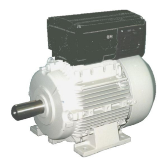
- Page 1 COMBIMASTER & MICROMASTER Integrated Operating Instructions SIEMENS...
-
Page 2: Table Of Contents
Options / Accessories ............13 Electrical Data | COMBIMASTER ........13 Electrical Data | MICROMASTER Integrated ..... 16 Parameter Summary List ............ 17 Technical Data, selection and ordering data (order numbers), accessories & availability are subject to change. © Siemens plc 1999 | G85139-H1731-U400-D2... -
Page 3: Safety And Ce Compliance
Use this equipment only for the purpose specified by the manufacturer. Do not carry out any modifications, or fit any spare parts which are not sold or recommended by the manufacturer; this could cause fires, electric shock or other injuries. © Siemens plc1999 | G85139-H1731-U400-D2... - Page 4 Case Size. For Case Sizes A and B, the fan COMBIMASTER products are suitable for must provide 0.42m /min and 1.25m /min incorporation into machinery. respectively. ISO 9001 Siemens plc operates a quality management system which complies with the requirements of ISO 9001. © Siemens plc 1999 | G85139-H1731-U400-D2...
-
Page 5: Installation
Bear It may be necessary to balance the whole in mind the type of balance used when fitting rotor and transmission element. the transmission element. © Siemens plc1999 | G85139-H1731-U400-D2... -
Page 6: Mechanical Installation | Micromaster Integrated
In most cases the MIP makes use of guidelines similar to those given above for the existing motor gasket. Refer to Siemens the COMBIMASTER. Document ‘MMI Motor Adaptation Guidelines’ (English) – (Available 2 1999.–... -
Page 7: Electrical Installation | Combimaster And Micromaster Integrated
Use a 4 - 5 mm cross-tip screwdriver to 4-core screened cable. If crimp terminals are tighten the terminal screws. used they must be insulated. If crimps are not used, the strip length must not exceed 5mm. © Siemens plc1999 | G85139-H1731-U400-D2... - Page 8 Check that the supply voltage is correct for the Access cover retaining screws 4.0Nm inverter used by referring to the rating label. Gland hole covers: 1.0Nm Mains connector screws 1.0Nm Cable Glands (Case Size B) PG21(Mains) Earth Connection 1.5Nm PG16(Signal) © Siemens plc 1999 | G85139-H1731-U400-D2...
- Page 9 Check that the supply voltage is correct for the Access cover retaining screws 4.0Nm inverter used by referring to the rating label. Gland hole covers: 1.0Nm Mains connector screws 1.0Nm Cable Glands (Case Size A) PG16 PL700 Screws 0.5Nm Earth Connection 1.5Nm © Siemens plc1999 | G85139-H1731-U400-D2...
-
Page 10: Control Cable Connections
(7.5 - 33V, max. 5mA) (0/2 - 10V, for Digital and (+15V, or 0/4 - 20mA) Analogue max. 50mA) Inputs (+10V, max. 10mA) PL800 (CS B) / PL700 (CS A) SK200 Socket Figure 4 Control Terminal Connections © Siemens plc 1999 | G85139-H1731-U400-D2... -
Page 11: Drive Operation
0 Hz and 50 Hz. separately). Regardless of its initial position, internal potentiometer R314 must be turned fully counter-clockwise before it will start the inverter. © Siemens plc1999 | G85139-H1731-U400-D2... -
Page 12: Basic Operation
JP301. changed by connecting the link to DIN2 Refit the cover, tighten the cover screws instead of DIN1. to the correct torque and then apply mains power to the inverter. © Siemens plc 1999 | G85139-H1731-U400-D2... -
Page 13: Operation - Digital Control
Switch power and then switch on again. off if the fault condition persists. Trips can be If the fault/warning persists, further reset by using DIN3. investigation requires an OPm2 or a serial link connection. © Siemens plc1999 | G85139-H1731-U400-D2... -
Page 14: Options / Accessories
CS B Electro-mechanical Brake Control 6SE9996-0XA10 Unit CS B Pulse Resistor Braking Unit 6SE9996-0XA11 SIMOVIS PC Software 6SE3290-0XX87-8SA2 Note: CS A covers power range 120W to 1.5kW CS B covers power range 1.5kW to 7.5kW © Siemens plc 1999 | G85139-H1731-U400-D2... -
Page 15: Electrical Data | Combimaster
4.7 A Mains fuse: 10 A Mains Lead cross- section * Note that these units are available Unfiltered only. Position 12 (shown as “.”) is for the construction type from the Siemens M11 catalogue.(Ref.: see above) © Siemens plc1999 | G85139-H1731-U400-D2... - Page 16 * [zz] = filter option: U = Unfiltered, A = Class A filter, B = Class B filter and mains voltage code: 2 = 380 – 500V, 3 = 460 – 500V/60Hz . Allowed combinations: A2, B2, U2 and U3. Position 12 (shown as “.”) is for the construction type from the Siemens M11 catalogue. (Ref.: see above) CS B High Voltage Three Phase Units...
-
Page 17: Electrical Data | Micromaster Integrated
Opm2 or serial link: 0 – 400Hz Input Current: 1.1 A 1.9 A 2.7 A 3.6 A 4.7 A Mains fuse: 10 A Mains Lead cross- section * Note that these units are available Unfiltered only. © Siemens plc1999 | G85139-H1731-U400-D2... -
Page 18: Parameter Summary List
PARAMETER SUMMARY LIST This list is applicable for operation using Opm2 – Clear Text Display (optional). G = Parameter can be changed during operation. ✩✩✩ = Value depends on the rating of the motor. © Siemens plc 1999 | G85139-H1731-U400-D2... - Page 19 Reverse motor direction P082 Nominal speed for motor (RPM) ✩✩✩ P041 G P083 Nominal current for motor (A) Fixed frequency 1 (Hz) 5.00 ✩✩✩ P042 G P084 Nominal voltage for motor (V) Fixed frequency 2 (Hz) 10.00 © Siemens plc1999 | G85139-H1731-U400-D2...
- Page 20 P141 Most recent fault code –1 P142 Most recent fault code –2 P143 Most recent fault code –3 P151 G Green LED function WARNING Please refer to the Reference Manual before changing any parameters. © Siemens plc 1999 | G85139-H1731-U400-D2...
- Page 21 Web Site: http://www.con.siemens.co.uk Herausgegeben vom Bereich Automatisierungs- und Antriebstechnik (A&D) Geschäftsgebiet Standard Drives Postfach 3269, D-91050 Erlangen Siemens plc Automation & Drives *6SE9996-0XA36* Standard Drives Division Siemens House Varey Road 6SE9996-0XA36 Congleton CW12 1PH...
Need help?
Do you have a question about the COMBIMASTER CM12 and is the answer not in the manual?
Questions and answers