
Related Manuals for Siemens MC45


Summary of Contents for Siemens MC45
- Page 1 Siemens Cellular Engine Hardware Interface Description Version 00.02 DocID: MC45_HD_01_V00.02a...
- Page 2 This product is not intended for use in life support appliances, devices or systems where a malfunction of the product can reasonably be expected to result in personal injury. Siemens AG customers using or selling this product for use in such applications do so at their own risk and agree to fully indemnify Siemens for any damages resulting from illegal use or resale.
-
Page 3: Table Of Contents
Power up / down scenarios ................33 3.3.1 Turn on MC45 ..................33 3.3.1.1 Turn on MC45 using the ignition line /IGT (Power on)....33 3.3.1.2 Timing of the ignition process ...........34 3.3.1.3 Turn on MC45 using the POWER signal ........35 3.3.1.4 Turn on MC45 using the RTC (Alarm mode) ......35 3.3.2... - Page 4 Electrical specifications of the application interface..........61 Antenna interface (antenna reference point – ARP) ..........65 Physical characteristics ...................66 Mechanical dimensions of MC45................66 Mounting MC45 onto the application platform ............69 Board-to-board connector ..................70 5.3.1 Mechanical dimensions of the Hirose DF12 connector ......71 5.3.2...
- Page 5 Figure 23: LED Circuit (Example) ..................59 Figure 24: Incoming voice call ....................60 Figure 25: Incoming data call ....................60 Figure 26: Pin assignment (top view on MC45) ..............61 Figure 27: MC45 – top view....................66 Figure 28: Mechanical dimensions of MC45.................67 Figure 29: MC45 bottom view....................68 Figure 30: Hirose DF12C receptacle on MC45 ..............70...
- Page 6 Table 14 : Pin assignment of Molex SIM card holder on DSB45 Support Box ......55 Table 15: Input control signals of the MC45 module.............57 Table 16: MC45 synchronization signal (if SYNC pin is set to mode 0 via AT^SSYNC)..58 Table 17: Coding of the status LED..................59 Table 18: MC45 ring signal....................60...
-
Page 7: Version History
(no more necessary to connect unused input pins to VDD). Corrected input voltage (peak to peak). Removed introduction. 66ff Updated MC45 drawings. Added bottom view and information about test points and ground pad. Added recommendations for installation. Table 21: Corrected HRS number of DF12C receptacle. - Page 8 MC45 Hardware Interface Description P R E L I M I N A R Y 6.4.1 79ff Added current consumption during transmit burst. 81ff Added notes on AT commands where applicable. Table 31: Modified MIC input signal in modes 5 and 6.
-
Page 9: Introduction
This document describes the hardware interface of the Siemens MC45 module that connects to the cellular device application and the air interface. As MC45 is intended to integrate with a wide range of application platforms, all functional components are described in great detail. -
Page 10: Terms And Abbreviations
Digital-to-Analog Converter Digital Audio Interface dBm0 Digital level, 3.14dBm0 corresponds to full scale, see ITU G.711, A-law Data Communication Equipment (typically modems, e.g. Siemens GSM engine) DCS 1800 Digital Cellular System, also referred to as PCN Discontinuous Reception Development Support Box... - Page 11 MC45 Hardware Interface Description P R E L I M I N A R Y Abbreviation Description FDMA Frequency Division Multiple Access Full Rate GMSK Gaussian Minimum Shift Keying GPRS General Packet Radio Service Global Standard for Mobile Communications High Impedance...
- Page 12 MC45 Hardware Interface Description P R E L I M I N A R Y Abbreviation Description Root Mean Square (value) Read-only Memory Real Time Clock Receive Direction Specific Absorption Rate SELV Safety Extra Low Voltage Subscriber Identification Module Short Message Service...
-
Page 13: Type Approval
P R E L I M I N A R Y 1.3 Type approval MC45 is designed to comply with the directives and standards listed below. Please note that the product is still in a pre-release state and, therefore, type approval and testing procedures have not yet been completed. - Page 14 Mobile phones, PDAs or other handheld transmitters and receivers incorporating a GSM module must be in accordance with the guidelines for human exposure to radio frequency energy. This requires the Specific Absorption Rate (SAR) of handheld MC45 based applications to be evaluated and approved for compliance with national and/or international regulations.
-
Page 15: Safety Precautions
The following safety precautions must be observed during all phases of the operation, usage, service or repair of any cellular terminal or mobile incorporating MC45. Manufacturers of the cellular terminal are advised to convey the following safety information to users and operating personnel and to incorporate these guidelines into all manuals supplied with the product. - Page 16 Compliance with FCC guidelines Fix-mount and mobile devices incorporating MC45 modules must be designed to maintain a minimum separation distance of 20 cm between the antenna and the end user to satisfy RF exposure requirements for mobile transmitting devices.
-
Page 17: Product Concept
P R E L I M I N A R Y 2 Product concept Designed for use on any GSM network in the world, Siemens MC45 is a tri-band GSM/GPRS engine that works on the three frequencies GSM 900 MHz, GSM 1800 MHz and GSM 1900 MHz. -
Page 18: Mc45 Key Features At A Glance
· GPRS data uplink transfer: max. 21.4 kbps (see Table 2) · Coding scheme: CS-1, CS-2, CS-3 and CS-4 · MC45 supports the two protocols PAP (Password Authentication Protocol) and CHAP (Challenge Handshake Authentication Protocol) commonly used for PPP connections. - Page 19 · Supported SIM card: 3V SIM interface · External SIM card reader has to be connected via interface connector (note that card reader is not part of MC45) External antenna Connected via 50 Ohm antenna connector or antenna pad Audio interfaces...
-
Page 20: Table 2: Coding Schemes And Maximum Net Data Rates Over Air Interface
MC45 Hardware Interface Description P R E L I M I N A R Y Table 2: Coding schemes and maximum net data rates over air interface Coding scheme 1 Timeslot 2 Timeslots 4 Timeslots CS-1: 9.05 kbps 18.1 kbps 36.2 kbps... -
Page 21: Circuit Concept
MC45 Hardware Interface Description P R E L I M I N A R Y 2.2 Circuit concept Figure 1 shows a block diagram of the MC45 module and illustrates the major functional components: · GSM / GPRS baseband processor ·... -
Page 22: Application Interface
P R E L I M I N A R Y 3 Application Interface MC45 is equipped with a 50-pin 0.5mm pitch board-to-board connector that connects to the cellular application platform. The host interface incorporates several sub-interfaces described in the following chapters: ·... -
Page 23: Operating Modes
MC45 Hardware Interface Description P R E L I M I N A R Y 3.1 Operating modes The table below briefly summarizes the various operating modes referred to in the following chapters. Table 3: Overview of operating modes Mode... - Page 24 Charge mode changes to Charge-only mode when operation the module is powered down before charging has been completed. See Table 10 and Table 12 for the various options of waking up MC45 and proceeding from one mode to another. MC45_HD_01_V00.02a Page 24 of 90 12.08.2002...
-
Page 25: Power Supply
MC45 Hardware Interface Description P R E L I M I N A R Y 3.2 Power supply The power supply of MC45 has to be a single voltage source of V = 3.3V...4.5V. It must BATT+ be able to provide sufficient current in a transmit burst which typically rises to 2A. Beyond that, the power supply must be able to account for increased current consumption if the module is exposed to inappropriate conditions, for example antenna mismatch. -
Page 26: Minimizing Power Losses
2A. It should be noted that MC45 switches off when exceeding these limits. Any voltage drops that may occur in a transmit burst should not exceed 400mV. For further details see Chapter 6.4. -
Page 27: Charging Control
In this case, MC45 needs to be powered from a Li-Ion battery pack, e.g. as specified in Table 6. The module only delivers, via its POWER line and CHARGE line, the control signals needed to start and stop the charging process. -
Page 28: Battery Pack Characteristics
The circuit must be insensitive to pulsed current. · On the MC45 module, a built-in measuring circuit constantly monitors the supply voltage. In the event of undervoltage, it causes MC45 to power down. Undervoltage thresholds are specific to the battery pack and must be evaluated for the intended model. When you evaluate undervoltage thresholds, consider both the current consumption of MC45 and of the application circuit. -
Page 29: Recommended Battery Pack
MC45 Hardware Interface Description P R E L I M I N A R Y 3.2.3.2 Recommended battery pack The following battery pack has been especially designed for use with MC45 modules. Table 6: Specifications of XWODA battery pack Product name, type XWODA, Li-Ion, 3.6V, 800mAh... -
Page 30: Implemented Charging Technique
POWER pins of the external charging circuit and of the module. If MC45 was in POWER DOWN mode, it turns on and enters the Charge-only mode along with fast charging (see also Chapter 3.3.1.3). -
Page 31: Operating Modes During Charging
(provided that sufficient voltage is applied). The charging process during the Normal mode is referred to as Charge mode. If the charger is connected to the POWER pin while MC45 is in POWER DOWN mode, MC45 goes into Charge-only mode. -
Page 32: Charger Requirements
3.3.1.1. When the engine is in Alarm mode there is no direct way to start charging, i.e. charging will not begin even though the charger connects to the POWER pin of MC45. See also Chapter 3.3.5 which summarizes the various options of changing the mode of operation. -
Page 33: Power Up / Down Scenarios
3.3.1.1 Turn on MC45 using the ignition line /IGT (Power on) To switch on MC45 the /IGT (Ignition) signal needs to be driven to ground level for at least 100ms. This can be accomplished using an open drain/collector driver in order to avoid current flowing into this pin. -
Page 34: Timing Of The Ignition Process
MC45 Hardware Interface Description P R E L I M I N A R Y 3.3.1.2 Timing of the ignition process When designing your application platform take into account that powering up MC45 requires the following steps. · The ignition line cannot be operated until V passes the level of 3.0V. -
Page 35: Turn On Mc45 Using The Power Signal
MC45 enters a restricted mode, referred to as Charge-only mode where only the charging algorithm will be launched. During the Charge-only mode MC45 is neither logged on to the GSM network nor is the RS- 232 interface fully accessible. To switch to normal operation and log on to the GSM network, the /IGT line needs to be activated. -
Page 36: Power Saving
CYCLIC SLEEP mode. The first wake-up event fully activates the module, enables the serial interface and terminates the power saving mode. In short, it takes MC45 back to the highest level of functionality <fun>=1. -
Page 37: Timing Of The /Cts Signal In Cyclic Sleep Modes
MC45 Hardware Interface Description P R E L I M I N A R Y The CYCLIC SLEEP mode is a dynamic process which alternatingly enables and disables the serial interface. The application must be configured to use hardware flow control. By setting/resetting the /CTS signal, the module indicates to the application when the UART is active. -
Page 38: Figure 10: Beginning Of Power Saving If Cfun=5
MC45 Hardware Interface Description P R E L I M I N A R Y Figure 10 illustrates the CFUN=5 mode, which resets the /CTS signal 2 seconds after the last character was sent or received. The UART is kept active for another 5 ms before power saving begins. -
Page 39: Wake Up Mc45 From Sleep Mode
P R E L I M I N A R Y 3.3.2.5 Wake up MC45 from SLEEP mode A wake-up event is any event that switches off the SLEEP mode and causes MC45 to return to full functionality. In short, it takes MC45 back to AT+CFUN=1. -
Page 40: Turn Off Mc45
The best and safest approach to powering down MC45 is to issue the AT^SMSO command. This procedure lets MC45 log off from the network and allows the software to enter into a secure state and safe data before disconnecting the power supply. -
Page 41: Emergency Shutdown Using /Emergoff Pin
Therefore, this procedure is intended only for use in case of emergency, e.g. if MC45 fails to shut down properly. The /EMERGOFF signal is available on the board-to-board connector. To control the /EMERGOFF line it is recommended to use an open drain / collector driver. -
Page 42: Automatic Shutdown
Proceeding from the measured temperature, MC45 sends an alert in the form of a URC and switches off when exceeding the critical limits: ·... -
Page 43: Undervoltage Shutdown If Battery Ntc Is Present
BATT_TEMP terminal. Thus, you can take advantage of this feature even though the application handles the charging process or MC45 is fed by a fixed supply voltage. All you need to do is executing the write command AT^SBC=<current> which automatically enables the presentation of URCs. -
Page 44: Shutdown In The Event Of Overvoltage
P R E L I M I N A R Y 3.3.4.4 Shutdown in the event of overvoltage Overvoltage protection is implemented in the PSU-ASIC. If the supply voltage raises to > 5.8V MC45 switches off automatically. In contrast to undervoltage shutdown BATT+ ·... -
Page 45: Summary Of State Transitions
P R E L I M I N A R Y 3.3.5 Summary of state transitions Table 12: State transitions of MC45 The table shows how to proceed from one mode to another (gray column = present mode, white columns = intended modes) Further mode èèè... -
Page 46: Rtc Backup
RTC from an external capacitor or a battery (rechargeable or non-chargeable). The capacitor is charged by the BATT+ line of MC45. If the voltage supply at BATT+ is disconnected the RTC can be powered by the capacitor. The size of the capacitor determines the duration of buffering when no voltage is applied to MC45, i.e. -
Page 47: Serial Interfaces
P R E L I M I N A R Y 3.5 Serial interfaces MC45 offers two serial interfaces, each operating at 2.65V level. All RS-232 signals on the board-to-board connector are low active. Both interfaces are implemented as a serial asynchronous transmitter and receiver conforming to ITU-T RS-232 Interchange Circuits DCE. - Page 48 Please note that when the RS-232(0) runs in Multiplex mode, the RS-232(1) cannot be used. The /DTR0 signal will only be polled once per second from the internal firmware of MC45. The /RING0 signal serves to indicate incoming calls and other types of URCs (Unsolicited Result Code).
-
Page 49: Audio Interfaces
TFSDAI Figure 16: Audio block diagram MC45 offers six audio modes which can be selected with the AT^SNFS command, no matter which of the three interfaces is currently active. The electrical characteristics of the voiceband part vary with the audio mode. For example, sending and receiving amplification, sidetone paths, noise suppression etc. -
Page 50: Microphone Circuit
MC45 Hardware Interface Description P R E L I M I N A R Y When shipped from factory, all audio parameters of MC45 are set to interface 1 and audio mode 1. This is the default configuration optimized for the Votronic HH-SI-30.3/V1.1/0 handset and used for type approving the Siemens reference configuration. -
Page 51: Speech Processing
The serial interface is always active if the external input data clock SLCK is present, i.e. the serial interface is not clocked by the DSP of the MC45 baseband processor. SLCK must be supplied from the application and can be in a frequency range between 0.2 and 10 MHz. -
Page 52: Figure 18: Dai Timing On Transmit Path
MC45 Hardware Interface Description P R E L I M I N A R Y Note: Before starting the data transfer the clock SCLK should be available for at least three cycles. After the transfer of the LSB0 the clock SCLK should be still available for at least three cycles. -
Page 53: Sim Interface
It is recommended that the total cable length between the board-to-board connector pins on MC45 and the pins of the card holder does not exceed 200 mm in order to meet the specifications of 3GPP TS 51.010-1 and to satisfy the requirements of EMC compliance. -
Page 54: Requirements For Using The Ccin Pin
CCIN signal: a) If, during startup of MC45, the CCIN signal on the SIM interface is high, then the status of the SIM card holder can be recognized each time the card is inserted or ejected. This can be easily achieved when the card holder comprises a card detect switch. -
Page 55: Design Considerations For Sim Card Holder
The schematic below is a sample configuration that illustrates the Molex SIM card holder located on the DSB45 Support Box (evaluation kit used for type approval of the Siemens MC45 reference setup, see [4]). X503 is the designation used for the SIM card holder in [4]. Molex card holder... -
Page 56: Grounding The Sim Interface
MC45 Hardware Interface Description P R E L I M I N A R Y 3.7.3 Grounding the SIM interface To ground the SIM interface you can proceed from several approaches, depending on your individual application design. The following information is just one of several options you can... -
Page 57: Control Signals
MC45 Hardware Interface Description P R E L I M I N A R Y 3.8 Control signals The following control signals are available (2.65V level). 3.8.1 Inputs Table 15: Input control signals of the MC45 module Signal Pin status Function Remarks... -
Page 58: Outputs
The characteristics of the synchronization signal are explained below. Table 16: MC45 synchronization signal (if SYNC pin is set to mode 0 via AT^SSYNC) Function Pin status... -
Page 59: Using The Sync Pin To Control A Status Led
Table 17: Coding of the status LED LED mode Operating status MC45 is off or run in SLEEP, Alarm or Charge-only mode 600 ms On / 600ms Off No SIM card inserted or no PIN entered, or network search in progress, or ongoing user authentication, or network login in progress. -
Page 60: Behaviour Of The /Ring0 Line (Rs-232(0) Interface Only)
URC upon the receipt of an SMS. As a result, if this URC type was activated with AT+CNMI=1,1, each incoming SMS causes the /RING0 line to go low. For more detailed information on URCs please refer the "MC45 AT Command Set". Table 18: MC45 ring signal Function Status Description Ring indication /RING0 Indicates an incoming call or URC. -
Page 61: Electrical Specifications Of The Application Interface
3.9 Electrical specifications of the application interface Please note that the reference voltages listed in Table 14 are the values measured directly on the MC45 module. They do not apply to the accessories connected. If an input pin is specified for V = 3.3V, be sure never to exceed the stated voltage. -
Page 62: Table 19: Pin Assignment And Electrical Description Of Application Interface
MC45 Hardware Interface Description P R E L I M I N A R Y Table 19: Pin assignment and electrical description of application interface Function Signal name Signal form and level Comments Power BATT+ = 3.3V to 4.5V Power supply input. - Page 63 MC45 Hardware Interface Description P R E L I M I N A R Y Function Signal name Signal form and level Comments Ignition /IGT Input to switch the mobile ≈ 100kW, C ≈ 1nF max = 0.5V at Imax = -20µA max = 2.3V...
- Page 64 MC45 Hardware Interface Description P R E L I M I N A R Y Function Signal name Signal form and level Comments RS-232 (0) /RXD0 First serial interface for AT max = 0.2V at I = 1mA interface commands or data stream.
-
Page 65: Antenna Interface (Antenna Reference Point - Arp)
The standard layout of MC45 comprises an antenna connector from Hirose assembled on the component side of the PCB (top view on MC45) plus a antenna pad placed on the bottom side. Both solutions can only be applied alternatively: Whenever an antenna is plugged to the Hirose connector, the pad must not be used. -
Page 66: Physical Characteristics
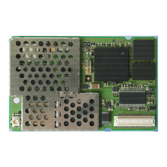
P R E L I M I N A R Y 5 Physical characteristics 5.1 Mechanical dimensions of MC45 Figure 27 shows the top view on MC45 and provides an overview of the mechanical dimensions of the board. For further details see Figure 28. Size: 53 +0.2 x 34 +0.2 x 3.5+0.3 mm... -
Page 67: Figure 28: Mechanical Dimensions Of Mc45
MC45 Hardware Interface Description P R E L I M I N A R Y Board-to-board connector All dimensions in millimeter Figure 28: Mechanical dimensions of MC45 MC45_HD_01_V00.02a Page 67 of 90 12.08.2002... -
Page 68: Figure 29: Mc45 Bottom View
P R E L I M I N A R Y Ground pad, e.g. for heat dissipator or connection to host device TP 402 14.42 4.75 0.00 10.60 TP GND TP BATT+ Figure 29: MC45 bottom view MC45_HD_01_V00.02a Page 68 of 90 12.08.2002... -
Page 69: Mounting Mc45 Onto The Application Platform
5.2 Mounting MC45 onto the application platform There are many ways to properly install MC45 in the host device. An efficient approach is to mount the MC45 PCB to a frame, plate, rack or chassis. Fasteners can be M1.6 or M1.8 screws plus suitable washers, circuit board spacers, or customized screws, clamps, or brackets. -
Page 70: Board-To-Board Connector
5.3 Board-to-board connector This chapter provides specifications for the 50-pin board-to-board connector which serves as physical interface to the host application. The receptacle assembled on the MC45 PCB is type Hirose DF12C. Mating headers from Hirose are available in different stacking heights. -
Page 71: Mechanical Dimensions Of The Hirose Df12 Connector
Type of cable: Flexible cable or flexible printed circuit board designed to mate with the Hirose receptacle and headers specified above. The equipment submitted for type approving the Siemens reference setup of MC45 includes a 160mm adapter cable. See Chapter 7.1. -
Page 72: Antenna Design
P R E L I M I N A R Y 5.4 Antenna design This chapter describes the various options of connecting an external antenna to MC45. Be sure that all peripherals are applied according to the manufacturer’s antenna specifications. -
Page 73: Figure 34: U.fl-R-Smt Connector With U.fl-Lp-040 Plug
MC45 Hardware Interface Description P R E L I M I N A R Y Temperature cycle No damage, cracks and looseness Temperature: +40°C ® 5 to 35°C of parts. ® +90°C ® 5 to 35°C Contact resistance: Time: 30 min. ® within 5 min. ®... -
Page 74: Figure 36: Specifications Of U.fl-Lp-(V)-040(01) Plug
MC45 Hardware Interface Description P R E L I M I N A R Y In addition to the connectors illustrated above, the U.FL-LP-(V)-040(01) version is offered as an extremely space saving solution. This plug is intended for use with extra fine cable (up to Æ... -
Page 75: Antenna Pad
CL331-04441-9 5.4.2 Antenna pad The antenna pad on the bottom of the MC45 PCB must not come into contact with the holding device or any other components of the host application. The pad must be a surrounded by a restricted area filled with air, which must also be reserved 0.8 mm in height. -
Page 76: Electrical, Reliability And Radio Characteristics
6.1 Absolute maximum ratings Absolute maximum ratings for supply voltage and voltages on digital and analog pins of MC45 are listed in Table 26. Exceeding these values will cause permanent damage to MC45. The power supply shall be compliant with the SELV safety standard defined in EN60950. -
Page 77: Reliability Characteristics
MC45 Hardware Interface Description P R E L I M I N A R Y 6.3 Reliability characteristics The test conditions stated below are an extract of the complete test specifications. Table 28: Summary of reliability test conditions Type of test... -
Page 78: Power Supply Ratings
MC45 Hardware Interface Description P R E L I M I N A R Y 6.4 Power supply ratings Table 29: Power supply ratings Parameter Description Conditions Unit BATT+ Supply voltage Reference points on MC45: TP BATT+ and TP GND... -
Page 79: Current Consumption During Transmit Burst
= 4.1V. BATT+ nom The reference points used on MC45 are the BATT+ and GND contacts (test points are shown in Figure 29). All curves are for one TX slot, that is, for example, a voice call, CSD call or Class 8 GPRS. Figures for Class 10 GPRS activities will be published in later releases of this document. -
Page 80: Figure 39: Typical Current Consumption Vs. Return Loss
MC45 Hardware Interface Description P R E L I M I N A R Y Burst Current : GSM Ch50 Average Current : GSM Ch50 3500 3000 2500 Pw rClass5 Pw rClass5 2000 Pw rClass10 Pw rClass10 Pw rClass15 Pw rClass15... -
Page 81: Electrical Characteristics Of The Voiceband Part
MC45 Hardware Interface Description P R E L I M I N A R Y 6.5 Electrical characteristics of the voiceband part 6.5.1 Setting audio parameters by AT commands The audio modes 2 to 6 can be adjusted according to the parameters listed below. Each audio mode is assigned a separate set of parameters. -
Page 82: Audio Programming Model
MC45 Hardware Interface Description P R E L I M I N A R Y 6.5.2 Audio programming model The audio programming model shows how the signal path can be influenced by varying the AT command parameters. The model is the same for all three interfaces, except for the parameters <outBbcGain>... -
Page 83: Characteristics Of Audio Modes
See AT^SNFO command in [1]. Audio mode 5 and 6 are identical. With AT^SAIC, you can easily switch mode 5 to the second interface. Therefore, audio mode 6 is only kept for compatibility to earlier Siemens GSM products. MC45_HD_01_V00.02a Page 83 of 90... -
Page 84: Voiceband Receive Path
MC45 Hardware Interface Description P R E L I M I N A R Y Note: With regard to acoustic shock, the cellular application must be designed to avoid sending false AT commands that might increase amplification, e.g. for a high sensitive earpiece. -
Page 85: Voiceband Transmit Path
MC45 Hardware Interface Description P R E L I M I N A R Y 6.5.5 Voiceband transmit path Test conditions: · The values specified below were tested to 1kHz and 0dB gain stage, unless otherwise stated. · Parameter setup: Audio mode = 5 for MICP1 to MICN1 and 6 for MICP2 to MICN2,... -
Page 86: Air Interface
Test conditions: All measurements have been performed at T = 25°C, V = 4.1V. BATT+ nom The reference points used on MC45 are the BATT+ and GND contacts (test points are shown in Figure 29). Table 34: Air Interface Parameter... -
Page 87: Electrostatic Discharge
Antenna interface: one spark discharge line (spark gap) SIM interface: clamp diodes for protection against overvoltage. The remaining ports of MC45 are not accessible to the user of the final product (since they are installed within the device) and therefore, are only protected according to the “Human Body Model”... -
Page 88: Reference Approval
MC45 Hardware Interface Description P R E L I M I N A R Y 7 Reference Approval 7.1 Reference Equipment The Siemens reference setup that will be submitted to type approve MC45 consists of the following components: · Siemens MC45 cellular engine ·... -
Page 89: List Of Parts And Accessories
+86-755-7623078 Email: Edward-lau@xwoda.com.cn Email: Andy-zhao@Xwoda.com.cn Info: Http://xwoda.com.cn DF12C board-to-board Hirose See Chapter 5.3 for details on receptacle on MC45 connector and mating headers Sales contacts are listed in Table 38. U.FL-R-SMT antenna Hirose See Chapter 5.4 for details on U.FL-R-SMT... -
Page 90: Table 37: Molex Sales Contacts (Subject To Change)
MC45 Hardware Interface Description P R E L I M I N A R Y Table 37: Molex sales contacts (subject to change) Molex Molex Deutschland GmbH American Headquarters For further information Felix-Wankel-Str. 11 Lisle, Illinois 60532 U.S.A. please click:...
Need help?
Do you have a question about the MC45 and is the answer not in the manual?
Questions and answers